US1908227A - Method and apparatus for drilling wells - Google Patents
Method and apparatus for drilling wells Download PDFInfo
- Publication number
- US1908227A US1908227A US421566A US42156630A US1908227A US 1908227 A US1908227 A US 1908227A US 421566 A US421566 A US 421566A US 42156630 A US42156630 A US 42156630A US 1908227 A US1908227 A US 1908227A
- Authority
- US
- United States
- Prior art keywords
- casing
- stem
- drilling
- drill stem
- drill
- Prior art date
- Legal status (The legal status is an assumption and is not a legal conclusion. Google has not performed a legal analysis and makes no representation as to the accuracy of the status listed.)
- Expired - Lifetime
Links
Images

Classifications
-
- E—FIXED CONSTRUCTIONS
- E21—EARTH OR ROCK DRILLING; MINING
- E21B—EARTH OR ROCK DRILLING; OBTAINING OIL, GAS, WATER, SOLUBLE OR MELTABLE MATERIALS OR A SLURRY OF MINERALS FROM WELLS
- E21B10/00—Drill bits
- E21B10/64—Drill bits characterised by the whole or part thereof being insertable into or removable from the borehole without withdrawing the drilling pipe
- E21B10/66—Drill bits characterised by the whole or part thereof being insertable into or removable from the borehole without withdrawing the drilling pipe the cutting element movable through the drilling pipe and laterally shiftable
Definitions
- This invention relates to new and useful improvements in a method and apparatus for drilling wells.
- One object of the invention is to provide apparatus of the character described specially designed for use in drilling wells where formation is encountered which has a tendency to cave in and embodies an outer casing adapted to maintain the walls against caving and an inner string, or stem, through which the drilling tool is driven, with interlocking means between said stem and easing whereby the latter may be moved, and rotated, from the former to prevent the casing from becoming stuck in the bore during drilling operations.
- Another object of the invention is to provide a novel type of collapsible drilling tool mounted in the stem and provided to work beneath the casing and which will be automatically collapsed, by the casing, upon withdrawal of the stem up through the casing, and which will automatically expand into drilling position, when the tool is lowered into position beneath said casing.
- a further feature of the invention is to provide a drilling apparatus of the character described of such construction that the drilling fluid may be circulated down through the drill stem and back up through the casing about the stem, or back up through the bore around the casing as desired.
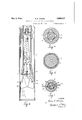
- Figure 2 shows a vertical sectional view of the upper end thereof.
- Figure 3 shows a vertical sectional view of the lower end of the apparatus showing the Figure 5 showsa cross sectional view taken on the line 55 of Figure 2, and
- Figure 6 shows a cross sectional view taken on the line 66 of Figurel. H
- the numeral 1 designates the well casing and the numeral 2 designates the drill stem therein to the lower end of which the drilling tool is attached.
- a preferred form of such tool will be hereinafter described.
- a grief stem 3, preferably square in cross section, is attached, by the coupling 4, to the upper end of the drill stem.
- the lower end of the coupling 4 is screwed into the connecting collar 5 of the drill stem and its upper end is reduced as at 5, and polygonal in form and beneath said reduced portion said coupling has an enlarged annular face 6.
- the upper end of the coupling 8 is thickened inwardly and is formed with the bearing 9, polygonal in cross sectional contour and shaped to snugly receive the upper end 5 of the coupling 4 thus forming, in effect, a clutch between the drill stem and easing when said upper end of said coupling 4 is seated in said bearing 9.
- Beneath said bearing 9 the coupling 8 has an internal annular seat 9 confronting the face 6.
- the drilling fluid may be forced down through the drill stem and returned back up through the casing 1 to the ground surface. If it be desired to return said drilling fluid up around the casing 1 the drill stem 2 may be elevated to seat the upper end 5' of the coupling t inthe bearing 9 with the face 6 seated against the seat 9 and this will block the upper end of the casing 1 and force returns up around the casing and out through the valve controlled line 29.
- the drill stem is elevated and the coupling 4L will engage the coupling 8 and the casing 1' will be elevated with the stem until the upper end of the casing is above the rotary drillingmachine and elevators may then be latched around the casing beneath the collar 7 and supported on the drilling machine to hold the casing elevated.
- the coupling 8 may then be unscrewed and picked up and held suspended by a block and tackle or other available means.
- the drill stem may be then further elevated and elevators latched therearound beneath the collar 5 and such elevators supported on the upper end of the casing l to support the drill stem.
- the grief joint 3 may then be broken out by unscrewing the 7 coupling 1 from the collar 5 and said grief joint swung to one side'and inserted through the joint, or section, to be added to the string of casing and the upper end of said casing joint connected to the coupling 8 and another joint or section, of the drill stem then attached to the coupling 4: and this assembly then swung back over the bore and the added joint of drill stem screwed into the coupling 5 and the elevators supporting the drill stem removed.
- the drill stem will be then sup ported from the derrick by the usual cable and tackle block operated from the draw works.
- the added joint of casing may then In the form shown there is a novel type of drilling tool shown.
- the lower end of the drill stem is shown flared and provided with the oppositely disposed downwardly flared inside seats 10, 10 and in said lower end of the stem there fixed the bearing member 11 having the vertical laterally: offset slots 12, 12 therethrough, which align with the respective seats 10, 10, thus forming shank bearings for the cutter shanks.
- the blades or cutters 13, 13, having the external upwardly facing shoulders 1 1, 1 1 thereon and whose upper ends have the upwardly tapering shanks 15, 15 which wedge in theshank bearings when the drilling tool is in operative position.
- the shanks 15 arev extended upwardly forming the arms 16,16 whose upper ends are pivotally connected to the lower ends of the links 17, 17.
- the upper ends of these links are connected to the lower end of the rod 18 which works'through a central bearing in the spfder19 and whose upper end has the head 20.
- the upper ends of the arms 16 have the shoulders 22, 22 thereon, provided to engage the bearing member 11, in case said arms should become detached so as to prevent the cutters from dropping into the bore.
- the arms 16 are offset outwardly with re lation to the upper end of the shanks 15 forming the inside shoulders 23, 23'which converge downwardly as shown more clearly in Figure 3 and which are provided fol a purpose to be hereinafter stated.
- the lower section or sections of the casing may be perforated forming a screen so that when an oil pro ducing stratum is reached the casing may be set with the screening sections thereof opposite the oil bearing stratum and the drilling stem, and drilling tool, withdrawn.
- the invention comprehends not only the apparatus, but its method of use as hereinabove illustrated.
- Drilling apparatus including an outer casing to be set in a well bore, a tubular drill stem therein, bore forming means on the stem underneath the casing, means through which the stem may be interlocked with the casing to impart rotation to th casing, from the stem, when the stem is elevated relative to the casing, said means being released when the stem is lowered relative to the casing.
- Drilling apparatus including an outer casing adapted to be set in a well bore, a tubular drill stem therein and spaced therefrom, bore forming means on the stem, said stem being movable through the casing, and rotatable independently thereof, means through which the stem may be interlocked with the casing to impart rotation thereto, when the stem is moved into one position, and released from said casing when the stem is moved into another position.
- Drilling apparatus including an outer casing, atubular drill stem therein and spaced therefrom and rotatable independent of the casing, drilling means on the stem, opposing seats one on the stem and the other in the casing, said stem being movable into one position to seat one of said seats against the other to close said space and into another position to carry the seats apart to open said space.
- Drilling apparatus including an outer casing adapted to be set in a well bore, a drill stem therein and spaced therefrom and rotatable independent of the casing, said drill stem having a fluid passageway therethrough, through which fluid may be forced down through the well bore and returned up through the casing around the stem, coacting means carried by the stem and easing, respectively, efiective to close said space, upon a se lected movement of the stem, to cause said fluid to return up through the bore on the out side of the-casing and adrilla tv the lower end '1 of thestem.
- Drilling apparatus including a' casing adapted to be set in a well here, a drill stem therein andspaced therefrom, bore forming means on the stem, interlocking means carried 1 by the stem and casing, respectively, whereby the.casing may be elevated "upon upward movement of the stem.
- 6.'Apparatu's of the character described including a casing adapted tobe set in a well bore, a drill stem therein and spaced therefrom and rotatable independently of the casing, drilling means on the stem, meanscarried by the casing and stem, respectively, adapted to be engaged, upon movement of l the. stem into one position, to establish adriving rela-' tion betweenth'e'stem and casing whereby the casing may be rotated from the stem.
- Apparatus of the character described including outer pipe in a well bore, a drill stem within said outer pipe, a collapsible drilling tool at the lower end of said stem shaped to underream said outer pipe, as drilling progresses, to permit said outer pipe to descend, said drill stem and drilling tool being withdrawable through said outer pipe, interconnecting means carried by said outer pipe and drill stem, respectively, through which said pipe and stem may be interconnected to rotate simultaneously, and disconnected to permit their independent rotation.
- Apparatus of the character described including an outer pipe in a well bore, a drill stem within said outer pipe, a drilling tool at the lower end of said stem shaped to underream said outer pipe, as drilling progrosses, to permit said outer pipe to descend, V
- stem through the outer pipe, means at the upper ends of said pipe. and stemthrough which thestem may be connected to the outer pipe to manipulate. the. same,- and disoonnected therefrom to rotate. independently thereofl 11,
- the method oi operations which consists in maintainingjajcasing anda' tubular drill.
- stem in the Well being through said stem'andreturning the. fluid aliternatively up through the casing and up:
Landscapes
- Engineering & Computer Science (AREA)
- Life Sciences & Earth Sciences (AREA)
- Geology (AREA)
- Mining & Mineral Resources (AREA)
- Mechanical Engineering (AREA)
- Physics & Mathematics (AREA)
- Environmental & Geological Engineering (AREA)
- Fluid Mechanics (AREA)
- General Life Sciences & Earth Sciences (AREA)
- Geochemistry & Mineralogy (AREA)
- Earth Drilling (AREA)
Description
May 9, 1933.
R. D. DODDS METHOD AND APPARATUS FOR DRILLING WELLS 2 Sheets-Sheet 1 INVENTOR.
ATT j Filed Jan. 17, 1930 May 9, 1933. R D, DODDS 1,908,227 I RATUS FOR I /q v 2, L Y
W\\ LL eeeeeeeeee T, 2
Patented May 9, 1933 UNITED STATES PATENT OFFICE .REDUS D. DODDS, OF HOUSTON, TEXAS, ASSIGITOR TO JAMES C. DOlJDS, OF HOUSTON,
TEXAS METHOD AND APPARATUS FOR- DRILLING WELLS 7 Application filed January 17, 1930. Serial No. 421,566. I
This invention relates to new and useful improvements in a method and apparatus for drilling wells.
One object of the invention is to provide apparatus of the character described specially designed for use in drilling wells where formation is encountered which has a tendency to cave in and embodies an outer casing adapted to maintain the walls against caving and an inner string, or stem, through which the drilling tool is driven, with interlocking means between said stem and easing whereby the latter may be moved, and rotated, from the former to prevent the casing from becoming stuck in the bore during drilling operations.
Another object of the invention is to provide a novel type of collapsible drilling tool mounted in the stem and provided to work beneath the casing and which will be automatically collapsed, by the casing, upon withdrawal of the stem up through the casing, and which will automatically expand into drilling position, when the tool is lowered into position beneath said casing.
A further feature of the invention is to provide a drilling apparatus of the character described of such construction that the drilling fluid may be circulated down through the drill stem and back up through the casing about the stem, or back up through the bore around the casing as desired.
With the above and other objects in view this invention has particular relation to certain novel features of construction, operation and arrangement of parts an example of which is given in this specification and illustrated in the accompanying drawings, wherein Figure 1 shows a vertical sectional view of the lower end of the apparatus in position for drilling.
Figure 2 shows a vertical sectional view of the upper end thereof.
Figure 3 shows a vertical sectional view of the lower end of the apparatus showing the Figure 5 showsa cross sectional view taken on the line 55 of Figure 2, and
Figure 6 shows a cross sectional view taken on the line 66 of Figurel. H
Referring now more particularly to the drawings, wherein like numerals of reference designate similar partsin each of the figures, the numeral 1 designates the well casing and the numeral 2 designates the drill stem therein to the lower end of which the drilling tool is attached. A preferred form of such tool will be hereinafter described. A grief stem 3, preferably square in cross section, is attached, by the coupling 4, to the upper end of the drill stem. The lower end of the coupling 4 is screwed into the connecting collar 5 of the drill stem and its upper end is reduced as at 5, and polygonal in form and beneath said reduced portion said coupling has an enlarged annular face 6. Attached to the upper end of the casing 1, by the collar 7, there is a coupling 8. The upper end of the coupling 8 is thickened inwardly and is formed with the bearing 9, polygonal in cross sectional contour and shaped to snugly receive the upper end 5 of the coupling 4 thus forming, in effect, a clutch between the drill stem and easing when said upper end of said coupling 4 is seated in said bearing 9. Beneath said bearing 9 the coupling 8 has an internal annular seat 9 confronting the face 6. j i
It is to be understood that while drilling the casing 1 will be supported at the ground surface by any suitable appliance provided for the purpose, usually by means of an elevator, or slips 28, around the outer casing beneath the collar 7 which in turn are sup-- ported by the convention surface casing 1 set in the upper end of the well bore and through which the casing 1 extends said slips closing the space between the casing 1, 1. It is to be further understood that the drill stem will be driven from the conventional rotary drilling machine and may be elevated and lowered through the conventional draw'work, all located at the surface of the ground.
In drilling the drilling fluid may be forced down through the drill stem and returned back up through the casing 1 to the ground surface. If it be desired to return said drilling fluid up around the casing 1 the drill stem 2 may be elevated to seat the upper end 5' of the coupling t inthe bearing 9 with the face 6 seated against the seat 9 and this will block the upper end of the casing 1 and force returns up around the casing and out through the valve controlled line 29.
In order to prevent the casing 1 frombecoming stuck in the bore, it'may be rotated from the stem when the upper end 5 of the coupling 4 is in the bearing 9; or said casing may be moved up and down through the instrumentality of said stem.
While drilling the drilling tool will be located a considerable distance beneath the lower end of the casing and the walls of the bore beneath the casing may be maintained against caving in by the pressure of the fluid in the bore. 7
As drilling proceeds and the bore is deepened it will become necessary, from time to time, to add other sections to the upper end of the casing as well as to the upper end of the stem. When this becomes necessary the drill stem is elevated and the coupling 4L will engage the coupling 8 and the casing 1' will be elevated with the stem until the upper end of the casing is above the rotary drillingmachine and elevators may then be latched around the casing beneath the collar 7 and supported on the drilling machine to hold the casing elevated. The coupling 8 may then be unscrewed and picked up and held suspended by a block and tackle or other available means. The drill stem may be then further elevated and elevators latched therearound beneath the collar 5 and such elevators supported on the upper end of the casing l to support the drill stem. The grief joint 3 may then be broken out by unscrewing the 7 coupling 1 from the collar 5 and said grief joint swung to one side'and inserted through the joint, or section, to be added to the string of casing and the upper end of said casing joint connected to the coupling 8 and another joint or section, of the drill stem then attached to the coupling 4: and this assembly then swung back over the bore and the added joint of drill stem screwed into the coupling 5 and the elevators supporting the drill stem removed. The drill stem will be then sup ported from the derrick by the usual cable and tackle block operated from the draw works. The added joint of casing may then In the form shown there is a novel type of drilling tool shown. The lower end of the drill stem is shown flared and provided with the oppositely disposed downwardly flared inside seats 10, 10 and in said lower end of the stem there fixed the bearing member 11 having the vertical laterally: offset slots 12, 12 therethrough, which align with the respective seats 10, 10, thus forming shank bearings for the cutter shanks. There are the blades or cutters 13, 13, having the external upwardly facing shoulders 1 1, 1 1 thereon and whose upper ends have the upwardly tapering shanks 15, 15 which wedge in theshank bearings when the drilling tool is in operative position. The shanks 15 arev extended upwardly forming the arms 16,16 whose upper ends are pivotally connected to the lower ends of the links 17, 17. The upper ends of these links are connected to the lower end of the rod 18 which works'through a central bearing in the spfder19 and whose upper end has the head 20. There is coil spring 21 seated on said spider and surrounding said rod on which said head rests. The upper ends of the arms 16 have the shoulders 22, 22 thereon, provided to engage the bearing member 11, in case said arms should become detached so as to prevent the cutters from dropping into the bore.
The arms 16 are offset outwardly with re lation to the upper end of the shanks 15 forming the inside shoulders 23, 23'which converge downwardly as shown more clearly in Figure 3 and which are provided fol a purpose to be hereinafter stated.
l Vhile drilling the wedge shaped shanks 15 are held by the spring 21 wedged in position in the lower end of the drill stem as above explained with the outside shoulders .4: of the blades 13 seated against the lower end of the drill stein. in this operative position, they are reinforced by the downwardly extending braces 25, 25 formed integrally with the lower end of the drill stem and which abut the rear sides of said cutters. When it is desired to move the drill stem upwardly through the casing or to entirely withdraw the drill stem and drilling tool upon such upward movement the outside shoulders 1 1 of the blades will contact against the casing shoe 26 at the lower end of the casing and upward movement of said blades will be temporarily stopped and as the drill stem moves on upwardly the spring 21 will be placed under compression. When the bearing member 11 passes up beyond the shoulders 23 the blades 13 will be collapsed or forced inwardly in the oosition shown in Figure 3 by the casing shoe 26 and the shoulders 23 will engage underneath the web 27 of the bearing member 11 and said shoulders 23 will be held interlocked underneath said web by reason of the fact that the blades 13 are held in collapsed position by their contact against the s des of the casing and the drill stem the drillingtool may be withdrawn from the casing or moved up and down at will in it. i
, As the drill stem and drilling tool are lowered into operative position the blades will be forced'downwardly by the web 27 and When the cutters are.
when the blades pass beneath the lower end of the drill stem the compression of the spring 21 will operate to cause the sloping shoulders 23 to disengage the web 27 and the said spring will then operate to pull the shanks 15 back up into their seats with the blades 13 in position for drilling and drilling may then be proceeded with.
It may be here noted that the lower section or sections of the casing may be perforated forming a screen so that when an oil pro ducing stratum is reached the casing may be set with the screening sections thereof opposite the oil bearing stratum and the drilling stem, and drilling tool, withdrawn.
The invention comprehends not only the apparatus, but its method of use as hereinabove illustrated.
The drawings and description disclose what is now considered to be a preferred form of the invention by way of illustration only, while the broad principle of the invention will be defined by the appended claims.
What I claim is:
1. Drilling apparatus including an outer casing to be set in a well bore, a tubular drill stem therein, bore forming means on the stem underneath the casing, means through which the stem may be interlocked with the casing to impart rotation to th casing, from the stem, when the stem is elevated relative to the casing, said means being released when the stem is lowered relative to the casing.
2. Drilling apparatus including an outer casing adapted to be set in a well bore, a tubular drill stem therein and spaced therefrom, bore forming means on the stem, said stem being movable through the casing, and rotatable independently thereof, means through which the stem may be interlocked with the casing to impart rotation thereto, when the stem is moved into one position, and released from said casing when the stem is moved into another position.
3. Drilling apparatus including an outer casing, atubular drill stem therein and spaced therefrom and rotatable independent of the casing, drilling means on the stem, opposing seats one on the stem and the other in the casing, said stem being movable into one position to seat one of said seats against the other to close said space and into another position to carry the seats apart to open said space.
4. Drilling apparatus including an outer casing adapted to be set in a well bore, a drill stem therein and spaced therefrom and rotatable independent of the casing, said drill stem having a fluid passageway therethrough, through which fluid may be forced down through the well bore and returned up through the casing around the stem, coacting means carried by the stem and easing, respectively, efiective to close said space, upon a se lected movement of the stem, to cause said fluid to return up through the bore on the out side of the-casing and adrilla tv the lower end '1 of thestem.
5. Drilling apparatus including a' casing adapted to be set in a well here, a drill stem therein andspaced therefrom, bore forming means on the stem, interlocking means carried 1 by the stem and casing, respectively, whereby the.casing may be elevated "upon upward movement of the stem.
6.'Apparatu's of the character described including a casing adapted tobe set in a well bore, a drill stem therein and spaced therefrom and rotatable independently of the casing, drilling means on the stem, meanscarried by the casing and stem, respectively, adapted to be engaged, upon movement of l the. stem into one position, to establish adriving rela-' tion betweenth'e'stem and casing whereby the casing may be rotated from the stem.
7 Apparatus of the character described in cluding a casing adapted to be set in atwell bore, a drill stem therein and spaced therefrom androtatable independently of the cas.-"
bore, a drill stem therein and spaced therefrom and rotatable independently of the casing, means on the stem for under reaming the casing, means carried by the casing and stem, respectively, adapted to be engaged, upon movement of the stem into one POSI- tion, to establish a driving relation between the stem and easing whereby the casing may be rotated from the stem, said means being arranged to disengage when said stem is moved to another position.
9. Apparatus of the character described including outer pipe in a well bore, a drill stem within said outer pipe, a collapsible drilling tool at the lower end of said stem shaped to underream said outer pipe, as drilling progresses, to permit said outer pipe to descend, said drill stem and drilling tool being withdrawable through said outer pipe, interconnecting means carried by said outer pipe and drill stem, respectively, through which said pipe and stem may be interconnected to rotate simultaneously, and disconnected to permit their independent rotation.
10. Apparatus of the character described including an outer pipe in a well bore, a drill stem within said outer pipe, a drilling tool at the lower end of said stem shaped to underream said outer pipe, as drilling progrosses, to permit said outer pipe to descend, V
' drilled and forcing drillingfluid. down'.
said drilling. tool-"being ,Wi thdrawable, by-
said stem, through the outer pipe, means at the upper ends of said pipe. and stemthrough which thestem may be connected to the outer pipe to manipulate. the. same,- and disoonnected therefrom to rotate. independently thereofl 11, In drilling a Well, the method oi operations which consists in maintainingjajcasing anda' tubular drill. stem in the Well being through said stem'andreturning the. fluid aliternatively up through the casing and up:
around the, outside of the casing.
- 12. In: drilling a Well the; method which: consists in operating a drillingtool through,
the casing in the Wellv by rotation and alter.- natively operatively connecting said. tool With the casing. and rotating the latter; and releasing said .tool from'the casing and rotating-the tool independently of the casing:
In testimony whereof I have signed my name to; this specification.
REDUS D. DO'DDS.
Priority Applications (1)
| Application Number | Priority Date | Filing Date | Title |
|---|---|---|---|
| US421566A US1908227A (en) | 1930-01-17 | 1930-01-17 | Method and apparatus for drilling wells |
Applications Claiming Priority (1)
| Application Number | Priority Date | Filing Date | Title |
|---|---|---|---|
| US421566A US1908227A (en) | 1930-01-17 | 1930-01-17 | Method and apparatus for drilling wells |
Publications (1)
| Publication Number | Publication Date |
|---|---|
| US1908227A true US1908227A (en) | 1933-05-09 |
Family
ID=23671083
Family Applications (1)
| Application Number | Title | Priority Date | Filing Date |
|---|---|---|---|
| US421566A Expired - Lifetime US1908227A (en) | 1930-01-17 | 1930-01-17 | Method and apparatus for drilling wells |
Country Status (1)
| Country | Link |
|---|---|
| US (1) | US1908227A (en) |
Cited By (5)
| Publication number | Priority date | Publication date | Assignee | Title |
|---|---|---|---|---|
| US2784942A (en) * | 1955-01-11 | 1957-03-12 | California Research Corp | Apparatus for simultaneously drilling and casing shot holes |
| US2929610A (en) * | 1954-12-27 | 1960-03-22 | Shell Oil Co | Drilling |
| US2948514A (en) * | 1955-05-17 | 1960-08-09 | Gebhard J Long | Rotary earth drilling apparatus and method |
| US3005504A (en) * | 1959-05-11 | 1961-10-24 | Gardner Denver Co | Drilling device |
| DE3010440A1 (en) * | 1980-03-19 | 1981-09-24 | Stumpp + Kurz Gmbh + Co, 7000 Stuttgart | DRILLING TOOL FOR MAKING ONE AND DOWEL FOR SHAPED INSERTION INTO A BIG DEPTH WITH A CONICAL EXTENSION |
-
1930
- 1930-01-17 US US421566A patent/US1908227A/en not_active Expired - Lifetime
Cited By (6)
| Publication number | Priority date | Publication date | Assignee | Title |
|---|---|---|---|---|
| US2929610A (en) * | 1954-12-27 | 1960-03-22 | Shell Oil Co | Drilling |
| US2784942A (en) * | 1955-01-11 | 1957-03-12 | California Research Corp | Apparatus for simultaneously drilling and casing shot holes |
| US2948514A (en) * | 1955-05-17 | 1960-08-09 | Gebhard J Long | Rotary earth drilling apparatus and method |
| US3005504A (en) * | 1959-05-11 | 1961-10-24 | Gardner Denver Co | Drilling device |
| DE3010440A1 (en) * | 1980-03-19 | 1981-09-24 | Stumpp + Kurz Gmbh + Co, 7000 Stuttgart | DRILLING TOOL FOR MAKING ONE AND DOWEL FOR SHAPED INSERTION INTO A BIG DEPTH WITH A CONICAL EXTENSION |
| US4410055A (en) * | 1980-03-19 | 1983-10-18 | Hilti Aktiengesellschaft | Drilling tool |
Similar Documents
| Publication | Publication Date | Title |
|---|---|---|
| US2148327A (en) | Oil well completion apparatus | |
| US3552507A (en) | System for rotary drilling of wells using casing as the drill string | |
| US4083405A (en) | Well drilling method and apparatus therefor | |
| US2834578A (en) | Reamer | |
| US3570603A (en) | Method and apparatus for cementing casing sections in well bores | |
| CN106715827B (en) | Liner drilling using retrievable directional bottom hole assembly | |
| US2136518A (en) | Pipe cutter | |
| US2950087A (en) | Combined rotary and percussion drilling | |
| US2782005A (en) | Well drilling bit | |
| US3489211A (en) | Method and apparatus for parting subsurface well casing from floating drilling vessels | |
| US2212067A (en) | Drilling apparatus | |
| US2229493A (en) | Method and apparatus for completing wells | |
| US2918259A (en) | Automatic slip joints | |
| US1908227A (en) | Method and apparatus for drilling wells | |
| US2162179A (en) | Oil well completion equipment | |
| US2382725A (en) | Rotary underreamer | |
| US3262501A (en) | Apparatus for pulling a well liner | |
| US1927310A (en) | Well cleaning apparatus | |
| US3126963A (en) | Well completion tool | |
| US2179033A (en) | Method and apparatus for performing fishing operations | |
| US2838283A (en) | Method and apparatus for drilling well holes | |
| US2137296A (en) | Well fluid sampler | |
| US3070170A (en) | Ball latch wash-over spear apparatus | |
| US2879849A (en) | Releasable fishing apparatus | |
| US2021184A (en) | Drilling structure and bit |