US1908219A - Art of removing silk from corn - Google Patents
Art of removing silk from corn Download PDFInfo
- Publication number
- US1908219A US1908219A US488218A US48821830A US1908219A US 1908219 A US1908219 A US 1908219A US 488218 A US488218 A US 488218A US 48821830 A US48821830 A US 48821830A US 1908219 A US1908219 A US 1908219A
- Authority
- US
- United States
- Prior art keywords
- corn
- silk
- tines
- rods
- slats
- Prior art date
- Legal status (The legal status is an assumption and is not a legal conclusion. Google has not performed a legal analysis and makes no representation as to the accuracy of the status listed.)
- Expired - Lifetime
Links
- 240000008042 Zea mays Species 0.000 title description 41
- 235000005824 Zea mays ssp. parviglumis Nutrition 0.000 title description 40
- 235000002017 Zea mays subsp mays Nutrition 0.000 title description 40
- 235000005822 corn Nutrition 0.000 title description 40
- XLYOFNOQVPJJNP-UHFFFAOYSA-N water Substances O XLYOFNOQVPJJNP-UHFFFAOYSA-N 0.000 description 10
- 239000000203 mixture Substances 0.000 description 9
- 238000000034 method Methods 0.000 description 8
- 230000001376 precipitating effect Effects 0.000 description 4
- 238000004140 cleaning Methods 0.000 description 3
- 238000010276 construction Methods 0.000 description 3
- 239000000835 fiber Substances 0.000 description 3
- 239000007788 liquid Substances 0.000 description 3
- 238000005192 partition Methods 0.000 description 3
- 239000012530 fluid Substances 0.000 description 2
- 239000012634 fragment Substances 0.000 description 2
- 239000007921 spray Substances 0.000 description 2
- 235000007244 Zea mays Nutrition 0.000 description 1
- 229940089639 cornsilk Drugs 0.000 description 1
- 230000005484 gravity Effects 0.000 description 1
- 238000007689 inspection Methods 0.000 description 1
- 239000000463 material Substances 0.000 description 1
- 239000002184 metal Substances 0.000 description 1
- 238000012986 modification Methods 0.000 description 1
- 230000004048 modification Effects 0.000 description 1
- 238000012856 packing Methods 0.000 description 1
- 239000002245 particle Substances 0.000 description 1
- 238000005507 spraying Methods 0.000 description 1
- 230000000153 supplemental effect Effects 0.000 description 1
- 239000001231 zea mays silk Substances 0.000 description 1
Images


Classifications
-
- A—HUMAN NECESSITIES
- A01—AGRICULTURE; FORESTRY; ANIMAL HUSBANDRY; HUNTING; TRAPPING; FISHING
- A01F—PROCESSING OF HARVESTED PRODUCE; HAY OR STRAW PRESSES; DEVICES FOR STORING AGRICULTURAL OR HORTICULTURAL PRODUCE
- A01F11/00—Threshing apparatus specially adapted for maize; Threshing apparatus specially adapted for particular crops other than cereals
- A01F11/06—Threshing apparatus specially adapted for maize; Threshing apparatus specially adapted for particular crops other than cereals for maize, e.g. removing kernels from cobs
-
- Y—GENERAL TAGGING OF NEW TECHNOLOGICAL DEVELOPMENTS; GENERAL TAGGING OF CROSS-SECTIONAL TECHNOLOGIES SPANNING OVER SEVERAL SECTIONS OF THE IPC; TECHNICAL SUBJECTS COVERED BY FORMER USPC CROSS-REFERENCE ART COLLECTIONS [XRACs] AND DIGESTS
- Y10—TECHNICAL SUBJECTS COVERED BY FORMER USPC
- Y10S—TECHNICAL SUBJECTS COVERED BY FORMER USPC CROSS-REFERENCE ART COLLECTIONS [XRACs] AND DIGESTS
- Y10S209/00—Classifying, separating, and assorting solids
- Y10S209/932—Fluid applied to items
Definitions
- the present invention relates in general to improvements lin the ai't'ot treating corn ⁇ after removal thereof from tlie'cobs, and relates more specifically to an improved method of and apparatus for removing the silk from thekernels preparatory to packing the latter in containers.
- a general object of the invention is to piovide an improved ⁇ process of removing silkA :from corn 'l-rernels, Wherebythe objectioning the improved process ot removingi silk from corn.
- object of the present invention t-o provide various improvements .fin the details of constructionof corn silkers ot the4 general type shown in said: prior pat- ..ent, whereby the structure oi" such devices is' ⁇ 60 simplified and the emciency thereof is enhanced to a maximum.
- a further specific Vobject of theinvention * is to provide a corn silker rin which the various parts are readily-accessible and remov-" able tor cleaning purposes, thus introducing minimum delay. in restoring the machine to y operating condition.
- Still another specific object ofr the invention is-to provide a silking ⁇ machine wherein tiie falling mixture ot silk fibres and kernels, is subjectedrto a relativelyv large number of silk removing Wires or tiiies Withini a ⁇ rela- ⁇ .tivelv confined space, and in .which the silk is automatically V.and veffectively removedA from the collecting tines.
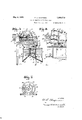
- Fig. S' is a transverse 'vertical section along the line13-3 ofi Fig. ⁇ 1 '100
- Fig. 4 is a transverse horizontal section through the improved corn silker, the section being taken along the line 4*4 of Fig. 1;
- Fig. 5 is a fragmentary enlarged horizontal section through the improved corn silker, the section being tak-en along the line 5 5 of Fig. 6;
- Fig. 6 is an enlarged front view of the fragment of the machine shown in Fig. 5;
- Fig. 7 is a fragmentary transverse vertical section through the improved corn silker, the section being taken on the line 7 7 of Fig. 1;
- Fig. 8 is a rear view of a fragment of the machine, showing the means for intermittently advancing the tine carrying belt.
- the main rectangular frame 8 has an upper portion 8 disposed some distance above the lower portion thereof.
- AnV oval tank or receptacle 9 is mounted midway between the upper and lower portions of the frame, and has its bottom portion 10 inclined downwardly and outwardly toward oppositely disposed discharge spouts 11, 12 located at the opposite sides of the receptacle 9.
- the spout 11 is adapted to discharge the silk libres, cleansing water, and other foreign particles, while the spout 12 is adapted to discharge the cleansed kernels of corn.
- An endless belt member 13 is positioned within lthe receptacle and extends around spaced sets of sprocket wheels 14, 15 which are mounted on vertical shafts 16.
- the shafts 16, 17 are journaled in brackets 18, 19 supported upon the main frame 8.
- the shafts 16, 17 are moreover spaced apart horizontally to substantially aline the belt member 13 with the interior of the confining receptacle, Vand the sprocketwheels of each set are spaced apart vertically so as to engage the end portions of the vertical slats 2O forming part of the belt member 13.
- the upper portions of the slats are provided with outwardly and downwardly extending arms 21 consisting of metal rods, and each of these rods is provided with outwardly extending fibre collecting wires or tines 22 formed of relatively thin wire and spaced equi-distant apart vertically to provide a silk removing cage.
- the arms 21 extend at an oblique angle to the vertical, so as to stagger the tines with respect to each other, and these arms are spaced apart so as to separate the tines approximately the same distance horizontally and vertically, thus insuring complete collection of the silk as the mixture of silk fibres and kernels is precipitated over the laterally advancing tines.
- the shaft 16 upon which the sprockets 14 are mounted extends upwardly through the bearing 18, and vis provided at its upper end with a ratchet wheel 23 rigidly attached to the shaft.
- An arm 24 journaled on the upper end of the shaft 16, has a spring pressed pawl connection 25 with the ratchet wheel, and is motion from the shaft 26 to the shaft 16.
- S-paced partitions 31, extend longitudinally within the tank 9 and are positioned between the outwardly and downwardly eX- tending arms 21 and the slats 20 forming part of the beltmember 13, these partitions serving to prevent the corn from being deflected by the tine cleansing sprays toward the water discharge side of the tank, and also serving to prevent the water from being deflected toward the corn discharge side of the tank.
- rlhe partitions 31, are of less lengtl'i than the receptacle 9 and the endless belt member 13, so as not to interfere with the rotation of the silk removing cage.
- a downwardly inclined supplemental frame 8 which is provided with roller bearings 33, 34.
- a cylindrical open ended and downwardly inclined screen is rotatably supported upon the roller bearings 33, 34, and has a flange 36 at the discharge end thereof which bears against the rollers of the bearing 34 to maintain the screen in position.
- the upper end of the screen is likewise provided with a flange 37 which engages the rollers of the bearing 33, and the flange 3711s provided with pins 38 by means of which the screen may be revolved about its longitudinal a-Xis and upon the roller bearings 33, 34.
- a second annular screen 39 is supported concentrically within the outer screen 35, and is provided at its discharge end with a flanged band 40 which bears upon the roller bearing 34 so as to support and to maintain ⁇ the inner screen in position.
- the upper end of the inner screen 39 is also provided with a flanged band 41 bearing against the rollers of the upper roller bearing 33, and this upper end of the inner screen is moreover provided with pins 42 similar to the pins 38 of the outer screen.
- a pin gear 43 mounted upon a countershaft 44 is positioned between the two sets of pins 38, 42, and imparts rotation to the inner and outer screens 35, 39 through the pins 38, 42 in reverse directions.
- the countershaft 44 is journaled upon the auX- iliary frame 8', and has a bevel gear connection 45 with the transverse shaft 26.
- a countershaft 48 is connected with thel transverse shaft 26 by means of bevel gears 49, and is journaled upon the auxiliary'frame 8"ex tending Vaxially into the circular chutel portion v47.
- a screw 'conveyor 50 is positioned within the circular chute portion47, being mounted upon the shaft 48 and being rotatable thereby to positively transport the mixture of corn and silk through the extension 47 and into the inner screen 39.
- a hopper is interposed betweenv the screen 35 and the corn discharge side of the receptacle 9,
- a short chute 89 is adapted to receive oversize which does not pass through the perforations of the screen 35 and directs such material away from the machine.
- the tubes 54 extend upwardly within the water and silk fibre discharge side of the receptacle 9, and are disposed at slight angles so as to make them substantially parallei to the arms 2T'which travel in close proximity to the tubes.
- the tubes 54 are spaced apart predetermined distances *with respect to the arms 21, and are provided with jet openings 54 disposedl in' horizontal aline ment with the adjacent wires or tines 22 so that the jets of water delivered from the orifices or openings of the tubes will directly impinge against the carrier arms and will strike the tines closely adjacent to the carrier arms thereof so as to force the silk or other foreign matter clinging to the tines, toward the outer free ends thereof.
- the disposition of the jet forming orifices and the direction of travel of the jets delivered therefrom, is clearly shown in Fig.
- each of the successive tine supports or arms 21 will be subjected to and washed by the single vertical series of jets flowing directly thereagainst, and each tine 22 will subsequently be subjected to and washed by two oppositely directed jets delivered at a slight angle against and along the opposite sides thereof, thus positively removing each bit o f foreign matter from each tine support and from the free end of each tine.
- the successive arms 21 and series of A tines 22 are intermittently advanced andare f therefore maintained in fixed position during that during: each period of rest, the vnext succeeding tine supporting arm 21 and series of f tines 22 will be positioned in proper relation withrespect to thev adjacent jets, and that all of the tines-will be thoroughly cleansed dun ling their passage through the cleaning chamber. f
- the mixture of corn kernels and silk fibres is supplied in bulk to the upper hopperf46 and the mixture is advanced by gravity and by the Vscrew conveyor into the inner revolving screen 39.
- the revolving screen 39 permits the-kernels of corn and the silk fibres to ⁇ pass through the -perforations thereof into the outer revolving screen 35, and the pieces of cob and some of the larger silk fibres will be discharged directly over the lower end of the y screen 39 into the discharge chute 39 -and thus removed from the machine.
- The-outer revolving ⁇ screen 35 will also separate some of the: foreign matter from the -mixturefvof cornkernels and silk fibres, and this remo-ved foreign matter will' likewise be discharged from-1 the machine over the chute 39.
- the remaining mixture of kernels and silk which passes through the perforations of the outer screen-35 is precipitated through the hopper 3.5 directly into vthe pathY of the advancing ⁇ tines 22 above the corn discharge spout'f12.
- the improved corn silker is highly eifec's' tive.
- the various parts ofthe machine are conveniently accessible for cleaning and ⁇ inspection, and the endless tine supporting band may be readily removed and reinstalled with minimum delay in operation of the imachine
- the machine is ordinarily furnished with several endlessV conveyors, so that one ⁇ maybe lutilized whenthe other is being cleaned, and provision is made formaintaining the mecha.- nism in 'highly' sanitary v-condition at all times.
- the amount of water required for removing the silk is relatively small due to the effective method of applying the jets to the tines, and the delivery of the jets longitudinally of the tines insures thorough removal of all foreign matter from the free ends of successive tines.
- an endless traveling member formed of a series of upright slats having rods depending from the upper portions thereof, said member having oppositely movable rectilineal stretches connected by curved end portions, a plurality of tines projecting laterally fro-m each of said rods and movable thereby, means for precipitating corn over said tines while supported by rods and slats comprising one cf said stretches to catch and to remove silk from the kernels, and means for directing jets of liquid along said tines toward the free ends thereof while supported by rods and slats comprising the other of said stretches and while said tines are disposed perpendicular to said other stretch to remove the accumulated silk.
- an endless traveling member formed of a series of upright slats and inclined rods depending from the upper ends thereof, said member having oppositely movable rectilineal stretches connected by curved end portions, a plurality of vertically offset tines projecting laterally from each of said rods and movable thereby, means for precipitating corn over said tines while supported by rods and slats comprising one of said stretches to catch and to remove silk from the kernels, and means for directing jets of liquid along said tines Vtoward the free ends thereof while supported by rods and slats comprising the other of said stretches and While said tines are parallel to each other and perpendicular to said other stretch to remove the accumulated silk.
- an endless traveling member formed of a series of upright slats and inclined rods depending from the upper ends thereof, said member having oppositely movable rectilinea-l stretches connected by curved end portions, an endless rail disposed between said slats and rods, a plurality of vertically offset tines proj ecting laterally from each of said rods and movable thereby, means for precipitating corn-over said tines While supported by rods and slats comprising one of said stretches and while said tines are parallel to each other and perpendicular to lsaid stretch to catch and to remove silk from the kernels, and means for directing jets of liquidalong said tines toward the free ends thereof while supported by rodsand slats comprising the other o-f said stretches and while said tines are parallel to each other and perpendicular to said other stretch to remove the accumulated silk.
- an endless traveling member formed of a series of upright slats and rods depending from the Aupper ends thereof and disposed at an angle thereto, said member having oppositely VInovable rectilineal stretches connected by curved end portions, an endless rail coacting with the cessive tines toward the free ends thereof while supported by rods and slats comprising the other of said stretches and while said tines are parallel to each other and perpendicular to said other stretch to rem-ove'the accumulated silk.
Landscapes
- Life Sciences & Earth Sciences (AREA)
- Environmental Sciences (AREA)
- Treatment Of Fiber Materials (AREA)
Description
May 9, 1933. F. D. CHAPMAN ART OF REMOVING SILK FROM CORN 3 Sheets-Sheet l Filed OCT.. l5, 1930l ATTORNEX.
May 9, 1933- F. D. CHAPMAN ART OF REMOVING 5114K FROM CORN Filed Oct. 13, 1930 3 Sheets-Sheet 2 INVENTOR.
A TTORNEY.
Patented May 9, 1933 U E STATES :FRANK D. CHAPMAN, OF BER-LN, WISCONSIN 'ART OF REi/EOVNG SILK FROIVE CORN 'Application filed-October 13,` 1930. `Serial .110. l288,218.
The present invention relates in general to improvements lin the ai't'ot treating corn `after removal thereof from tlie'cobs, and relates more specifically to an improved method of and apparatus for removing the silk from thekernels preparatory to packing the latter in containers.
f A general object of the invention is to piovide an improved` process of removing silkA :from corn 'l-rernels, Wherebythe objectioning the improved process ot removingi silk from corn.
It has heretofore been' proposed to separate silk trom kernels ot corn after remov- -Ward theirtree outer extremities.
al thereof from the cobs, by precipitating the mixture ot the silk and kernels over a series of sudostantially` horizontal longitudinally movable Wires7 to thereby cause the advancing Wires to catch the silk fibres and to perm`t the' kernels to tall freely into a hopper `disposed beneath the Wires. "ln this prior corn silker, it ivasattempted to remove the accumulated silk fibres from the longitudinally advancing Wires with the aid of Scrapers and subsequent sprays of Water, the latter being delivered transversely against the ivires after removal `ot the bulk of the silk libres by the scrapers. The characteristics of corn silk libres are however such that thisv prior spraying method did not in tact remove the fibres from the Wires, but
causedthe same to cling more closely and tenaciously to the surfaces of theivvires.
In my prior Patent # 1,8345047, granted December 1st, 1931 is shown lan improved cornsilker wherein` the use of undesirable sera-pers is avoided, and the silk libres are effectively collected upon transversely moving Wires or tines, being subsequently more effectively and completely removed by means of jets ot Water or other fluid Idelivered longitudinally along the Wires and tothis improved silker, the fibres are not only more effectivelyV removed from thelkerna-ls `l/Vith p `through the @improved corn silker, ij-taken and collected upon the `Wires Whichvmove laterally through ther path of the 'falling mixture, but the collected libres are `also quickly and effectivelyl removed from l.the Wires by the fluid jets. 55 lt isa more specific. object of the present invention t-o provide various improvements .fin the details of constructionof corn silkers ot the4 general type shown in said: prior pat- ..ent, whereby the structure oi" such devices is'` 60 simplified and the emciency thereof is enhanced to a maximum.
A further specific Vobject of theinvention *is to provide a corn silker rin which the various parts are readily-accessible and remov-" able tor cleaning purposes, thus introducing minimum delay. in restoring the machine to y operating condition.
Still another specific object ofr the invention :is-to provide a silking` machine wherein tiie falling mixture ot silk fibres and kernels, is subjectedrto a relativelyv large number of silk removing Wires or tiiies Withini a` rela-` .tivelv confined space, and in .which the silk is automatically V.and veffectively removedA from the collecting tines. j
VThese and other objectsand advantages of the present invention, Will appear from .the following detailed'description.v Y o Some of the. novel Vfeatures of corn Silker construction, disclosed butV not specifically claimed herein, form the subject of said patent.
A clear conception of the several steps ot the improved method, and ot the 4details ot construction'and mode of operationoi `one form of apparatus capable of exploiting the .improved method, may be had-by referring to the draw-ings accompanying and forming y a part of this specification in Which like refu erence characters designate the sameor similar parts in the various vievvs':
vsilker shown in Fig. 1; 1
Fig. S'is a transverse 'vertical section along the line13-3 ofi Fig.` 1 '100 Fig. 4 is a transverse horizontal section through the improved corn silker, the section being taken along the line 4*4 of Fig. 1;
Fig. 5 is a fragmentary enlarged horizontal section through the improved corn silker, the section being tak-en along the line 5 5 of Fig. 6;
Fig. 6 is an enlarged front view of the fragment of the machine shown in Fig. 5;
Fig. 7 is a fragmentary transverse vertical section through the improved corn silker, the section being taken on the line 7 7 of Fig. 1; and
Fig. 8 is a rear view of a fragment of the machine, showing the means for intermittently advancing the tine carrying belt.
Referring specifically to the drawings showing one embodiment of corn silker adapted to automatically exploit the improved process, the main rectangular frame 8 has an upper portion 8 disposed some distance above the lower portion thereof.V AnV oval tank or receptacle 9 is mounted midway between the upper and lower portions of the frame, and has its bottom portion 10 inclined downwardly and outwardly toward oppositely disposed discharge spouts 11, 12 located at the opposite sides of the receptacle 9. The spout 11 is adapted to discharge the silk libres, cleansing water, and other foreign particles, while the spout 12 is adapted to discharge the cleansed kernels of corn. An endless belt member 13 is positioned within lthe receptacle and extends around spaced sets of sprocket wheels 14, 15 which are mounted on vertical shafts 16. 17. The shafts 16, 17 are journaled in brackets 18, 19 supported upon the main frame 8. The shafts 16, 17 are moreover spaced apart horizontally to substantially aline the belt member 13 with the interior of the confining receptacle, Vand the sprocketwheels of each set are spaced apart vertically so as to engage the end portions of the vertical slats 2O forming part of the belt member 13. The upper portions of the slats are provided with outwardly and downwardly extending arms 21 consisting of metal rods, and each of these rods is provided with outwardly extending fibre collecting wires or tines 22 formed of relatively thin wire and spaced equi-distant apart vertically to provide a silk removing cage. The arms 21 extend at an oblique angle to the vertical, so as to stagger the tines with respect to each other, and these arms are spaced apart so as to separate the tines approximately the same distance horizontally and vertically, thus insuring complete collection of the silk as the mixture of silk fibres and kernels is precipitated over the laterally advancing tines.
The shaft 16 upon which the sprockets 14 are mounted, extends upwardly through the bearing 18, and vis provided at its upper end with a ratchet wheel 23 rigidly attached to the shaft. An arm 24 journaled on the upper end of the shaft 16, has a spring pressed pawl connection 25 with the ratchet wheel, and is motion from the shaft 26 to the shaft 16.
S-paced partitions 31, extend longitudinally within the tank 9 and are positioned between the outwardly and downwardly eX- tending arms 21 and the slats 20 forming part of the beltmember 13, these partitions serving to prevent the corn from being deflected by the tine cleansing sprays toward the water discharge side of the tank, and also serving to prevent the water from being deflected toward the corn discharge side of the tank. rlhe partitions 31, are of less lengtl'i than the receptacle 9 and the endless belt member 13, so as not to interfere with the rotation of the silk removing cage.
Located upon the corn discharge side of the receptacle 5) and above this receptacle, is a downwardly inclined supplemental frame 8 which is provided with roller bearings 33, 34. A cylindrical open ended and downwardly inclined screen is rotatably supported upon the roller bearings 33, 34, and has a flange 36 at the discharge end thereof which bears against the rollers of the bearing 34 to maintain the screen in position. The upper end of the screen is likewise provided with a flange 37 which engages the rollers of the bearing 33, and the flange 3711s provided with pins 38 by means of which the screen may be revolved about its longitudinal a-Xis and upon the roller bearings 33, 34.
A second annular screen 39 is supported concentrically within the outer screen 35, and is provided at its discharge end with a flanged band 40 which bears upon the roller bearing 34 so as to support and to maintain `the inner screen in position. The upper end of the inner screen 39 is also provided with a flanged band 41 bearing against the rollers of the upper roller bearing 33, and this upper end of the inner screen is moreover provided with pins 42 similar to the pins 38 of the outer screen. A pin gear 43 mounted upon a countershaft 44, is positioned between the two sets of pins 38, 42, and imparts rotation to the inner and outer screens 35, 39 through the pins 38, 42 in reverse directions. The countershaft 44 is journaled upon the auX- iliary frame 8', and has a bevel gear connection 45 with the transverse shaft 26.
iii() lli ' -v se igeosgzie A feed hopper 47 mounted upon the auxiliary frame 8 above the: axes-of the revolving screens, is provided witha lower chute portion 47 having an open ended-extension 47 which projects into the upper end'of the inner screen 39 to feed the mixture of corn kernels and silk `fibres thereto. A countershaft 48 is connected with thel transverse shaft 26 by means of bevel gears 49, and is journaled upon the auxiliary'frame 8"ex tending Vaxially into the circular chutel portion v47. A screw 'conveyor 50 is positioned within the circular chute portion47, being mounted upon the shaft 48 and being rotatable thereby to positively transport the mixture of corn and silk through the extension 47 and into the inner screen 39. A hopper is interposed betweenv the screen 35 and the corn discharge side of the receptacle 9,
so as to direct the corn or other materialdelivered through the screen 35 into the corn Vkernel discharge side of the receptacle l9. A short chute 89 is adapted to receive oversize which does not pass through the perforations of the screen 35 and directs such material away from the machine.
A water supply pipe 51 having a control valve 52 therein, is provided with a fitting 53 from which three spaced pipes or jet tubes I 54 extend. The tubes 54 extend upwardly within the water and silk fibre discharge side of the receptacle 9, and are disposed at slight angles so as to make them substantially parallei to the arms 2T'which travel in close proximity to the tubes. The tubes 54 are spaced apart predetermined distances *with respect to the arms 21, and are provided with jet openings 54 disposedl in' horizontal aline ment with the adjacent wires or tines 22 so that the jets of water delivered from the orifices or openings of the tubes will directly impinge against the carrier arms and will strike the tines closely adjacent to the carrier arms thereof so as to force the silk or other foreign matter clinging to the tines, toward the outer free ends thereof. 1The disposition of the jet forming orifices and the direction of travel of the jets delivered therefrom, is clearly shown in Fig. 5, and it will be noted that two of the three jets comprising each horizontal set, are delivered at opposite slight angles along the intervening tine, while the remaining jet of the series is delivered against the adjacent tine support or arm 21. `With this arrangement of the jets, each of the successive tine supports or arms 21 will be subjected to and washed by the single vertical series of jets flowing directly thereagainst, and each tine 22 will subsequently be subjected to and washed by two oppositely directed jets delivered at a slight angle against and along the opposite sides thereof, thus positively removing each bit o f foreign matter from each tine support and from the free end of each tine. The successive arms 21 and series of A tines 22are intermittently advanced andare f therefore maintained in fixed position during that during: each period of rest, the vnext succeeding tine supporting arm 21 and series of f tines 22 will be positioned in proper relation withrespect to thev adjacent jets, and that all of the tines-will be thoroughly cleansed dun ling their passage through the cleaning chamber. f
During normal operation of the corn silker,v the mixture of corn kernels and silk fibres is supplied in bulk to the upper hopperf46 and the mixture is advanced by gravity and by the Vscrew conveyor into the inner revolving screen 39. The revolving screen 39 permits the-kernels of corn and the silk fibres to `pass through the -perforations thereof into the outer revolving screen 35, and the pieces of cob and some of the larger silk fibres will be discharged directly over the lower end of the y screen 39 into the discharge chute 39 -and thus removed from the machine.
n The-outer revolving `screen 35 will also separate some of the: foreign matter from the -mixturefvof cornkernels and silk fibres, and this remo-ved foreign matter will' likewise be discharged from-1 the machine over the chute 39. The remaining mixture of kernels and silk which passes through the perforations of the outer screen-35 is precipitated through the hopper 3.5 directly into vthe pathY of the advancing `tines 22 above the corn discharge spout'f12.
As the inclined supporting arms position the successive tines 22 in vertically staggered re-` lation with respect to eachother, thekernels of-corn will naturally follow a zigzag'course while passing downwardly between the tines,
; thus insuring catching of all of the silk libres between themultiplicityof tines 22. The corn kernels eventually drop from the path of the tines upon the inclined bottom portion of the receptacle 9 and the cleang'corn is discharged through the chute 12.
ing, are eventually moved into the cleansing chamber where the jets of water are delivered therealong as previously described. It has been found in actual commercial operation,
that the improved corn silker is highly eifec's' tive. The various parts ofthe machine are conveniently accessible for cleaning and` inspection, and the endless tine supporting band may be readily removed and reinstalled with minimum delay in operation of the imachine The machine is ordinarily furnished with several endlessV conveyors, so that one` maybe lutilized whenthe other is being cleaned, and provision is made formaintaining the mecha.- nism in 'highly' sanitary v-condition at all times. The amount of water required for removing the silk, is relatively small due to the effective method of applying the jets to the tines, and the delivery of the jets longitudinally of the tines insures thorough removal of all foreign matter from the free ends of successive tines.
It should be understood that it is not desired to limit the invention to the'eXact steps of the method or to the exact details of construction herein shown and described, for various modifications within the scope of the claims may occur to persons skilled in the art.
It is claimed and desired to secure by Letters Patent:
1. In a corn silker, an endless traveling member formed of a series of upright slats having rods depending from the upper portions thereof, said member having oppositely movable rectilineal stretches connected by curved end portions, a plurality of tines projecting laterally fro-m each of said rods and movable thereby, means for precipitating corn over said tines while supported by rods and slats comprising one cf said stretches to catch and to remove silk from the kernels, and means for directing jets of liquid along said tines toward the free ends thereof while supported by rods and slats comprising the other of said stretches and while said tines are disposed perpendicular to said other stretch to remove the accumulated silk.
2. In a. corn silker, an endless traveling member formed of a series of upright slats and inclined rods depending from the upper ends thereof, said member having oppositely movable rectilineal stretches connected by curved end portions, a plurality of vertically offset tines projecting laterally from each of said rods and movable thereby, means for precipitating corn over said tines while supported by rods and slats comprising one of said stretches to catch and to remove silk from the kernels, and means for directing jets of liquid along said tines Vtoward the free ends thereof while supported by rods and slats comprising the other of said stretches and While said tines are parallel to each other and perpendicular to said other stretch to remove the accumulated silk.
3. In a corn silker, an endless traveling member formed of a series of upright slats and inclined rods depending from the upper ends thereof, said member having oppositely movable rectilinea-l stretches connected by curved end portions, an endless rail disposed between said slats and rods, a plurality of vertically offset tines proj ecting laterally from each of said rods and movable thereby, means for precipitating corn-over said tines While supported by rods and slats comprising one of said stretches and while said tines are parallel to each other and perpendicular to lsaid stretch to catch and to remove silk from the kernels, and means for directing jets of liquidalong said tines toward the free ends thereof while supported by rodsand slats comprising the other o-f said stretches and while said tines are parallel to each other and perpendicular to said other stretch to remove the accumulated silk.
4L. In a corn silker,`an endless traveling member formed of a series of upright slats and rods depending from the upper ends thereof and disposed at an angle thereto, said member having oppositely movable rectilineal stretches connected by curved end portions, an endless rail coacting with the upper portions of said rods between the rods and the adjacent slats, said slats and certain rods being freely vertically removable fr-om said rail, a plurality of tines projecting laterally from each of said rods and movable thereby, means vfor reci itatin corn over said tines while supported by rods andslats comprising one of said` stretches to catch and to remove silk from the kernels, and a series of stationary perforated pipes for directing jets of liquid along kopposite sides of the successive tines toward the free ends thereof while supported by rods and slats comprising the other of said stretches to remove the accumulated silk.
5. In a co-rn silker, an endless traveling member formed of a series of upright slats and rods depending from the Aupper ends thereof and disposed at an angle thereto, said member having oppositely VInovable rectilineal stretches connected by curved end portions, an endless rail coacting with the cessive tines toward the free ends thereof while supported by rods and slats comprising the other of said stretches and while said tines are parallel to each other and perpendicular to said other stretch to rem-ove'the accumulated silk.
In testimony whereof, I aliix my signature.
FRANK l). CHAPMAN.
upper portions of said rods between the rods .100
Priority Applications (1)
| Application Number | Priority Date | Filing Date | Title |
|---|---|---|---|
| US488218A US1908219A (en) | 1930-10-13 | 1930-10-13 | Art of removing silk from corn |
Applications Claiming Priority (1)
| Application Number | Priority Date | Filing Date | Title |
|---|---|---|---|
| US488218A US1908219A (en) | 1930-10-13 | 1930-10-13 | Art of removing silk from corn |
Publications (1)
| Publication Number | Publication Date |
|---|---|
| US1908219A true US1908219A (en) | 1933-05-09 |
Family
ID=23938816
Family Applications (1)
| Application Number | Title | Priority Date | Filing Date |
|---|---|---|---|
| US488218A Expired - Lifetime US1908219A (en) | 1930-10-13 | 1930-10-13 | Art of removing silk from corn |
Country Status (1)
| Country | Link |
|---|---|
| US (1) | US1908219A (en) |
Cited By (1)
| Publication number | Priority date | Publication date | Assignee | Title |
|---|---|---|---|---|
| US20100209228A1 (en) * | 2009-02-18 | 2010-08-19 | Pioneer Hi-Bred International, Inc. | Apparatus and system for preparing ears of corn for automated handling, positioning and orienting |
-
1930
- 1930-10-13 US US488218A patent/US1908219A/en not_active Expired - Lifetime
Cited By (3)
| Publication number | Priority date | Publication date | Assignee | Title |
|---|---|---|---|---|
| US20100209228A1 (en) * | 2009-02-18 | 2010-08-19 | Pioneer Hi-Bred International, Inc. | Apparatus and system for preparing ears of corn for automated handling, positioning and orienting |
| US20100209576A1 (en) * | 2009-02-18 | 2010-08-19 | Pioneer Hi-Bred International, Inc. | Method for preparing ears of corn for automated handling, positioning and orienting |
| US8579118B2 (en) * | 2009-02-18 | 2013-11-12 | Pioneer Hi-Bred International, Inc. | Method for preparing ears of corn for automated handling, positioning and orienting |
Similar Documents
| Publication | Publication Date | Title |
|---|---|---|
| US2652588A (en) | Apparatus for recovering oysters | |
| US1943775A (en) | Vegetable cleansing and blanching apparatus | |
| US2329333A (en) | Dewatering screen | |
| US3851572A (en) | Dry peeling apparatus | |
| US2383268A (en) | Method and apparatus for removing the stems and caps from berries and similar types ot fruit, etc. | |
| US2219809A (en) | Apparatus for handling vegetables or the like | |
| US1908219A (en) | Art of removing silk from corn | |
| US1989562A (en) | Method and apparatus for conditioning fibrous material | |
| US1801572A (en) | Machine for applying shredded material to confection-coated wafers and the like | |
| US2910992A (en) | Can washer | |
| US3855916A (en) | Dry peeling apparatus | |
| US1761492A (en) | Bottle-washing machine | |
| US2287447A (en) | Cleaning means for fruits, vegetables, etc. | |
| US2714411A (en) | Cherry stemming and sorting machine and method | |
| US2503556A (en) | Vegetable washer | |
| US2456040A (en) | Prerinsing apparatus for container washers | |
| US2286393A (en) | Vegetable cleaner | |
| US1964430A (en) | Fruit and vegetable cleaning machine | |
| US1864085A (en) | Fruit washing apparatus | |
| US568685A (en) | Bottle-washer | |
| US1222008A (en) | Cleaner and scalder. | |
| US1927721A (en) | Cleaner and polisher | |
| US2307257A (en) | Apparatus for handling vegetables or the like | |
| US2257470A (en) | Device for cleaning sweet corn | |
| US1834047A (en) | Corn silker |