US1908174A - Drill string coupling - Google Patents
Drill string coupling Download PDFInfo
- Publication number
- US1908174A US1908174A US569900A US56990031A US1908174A US 1908174 A US1908174 A US 1908174A US 569900 A US569900 A US 569900A US 56990031 A US56990031 A US 56990031A US 1908174 A US1908174 A US 1908174A
- Authority
- US
- United States
- Prior art keywords
- stem
- tool
- string
- piston
- fluid
- Prior art date
- Legal status (The legal status is an assumption and is not a legal conclusion. Google has not performed a legal analysis and makes no representation as to the accuracy of the status listed.)
- Expired - Lifetime
Links
- 230000008878 coupling Effects 0.000 title description 2
- 238000010168 coupling process Methods 0.000 title description 2
- 238000005859 coupling reaction Methods 0.000 title description 2
- 239000012530 fluid Substances 0.000 description 24
- 238000005553 drilling Methods 0.000 description 11
- 241000251468 Actinopterygii Species 0.000 description 7
- 238000012856 packing Methods 0.000 description 6
- 238000004891 communication Methods 0.000 description 5
- 238000007789 sealing Methods 0.000 description 4
- 230000015572 biosynthetic process Effects 0.000 description 3
- 238000010276 construction Methods 0.000 description 3
- 239000013049 sediment Substances 0.000 description 3
- 239000007787 solid Substances 0.000 description 3
- 229910000831 Steel Inorganic materials 0.000 description 2
- 239000010959 steel Substances 0.000 description 2
- 229910001018 Cast iron Inorganic materials 0.000 description 1
- 102000004726 Connectin Human genes 0.000 description 1
- 108010002947 Connectin Proteins 0.000 description 1
- 101100533615 Schizosaccharomyces pombe (strain 972 / ATCC 24843) end4 gene Proteins 0.000 description 1
- 230000002452 interceptive effect Effects 0.000 description 1
- 239000000463 material Substances 0.000 description 1
- 229920000136 polysorbate Polymers 0.000 description 1
- 230000000284 resting effect Effects 0.000 description 1
- 230000000717 retained effect Effects 0.000 description 1
Images
Classifications
-
- E—FIXED CONSTRUCTIONS
- E21—EARTH OR ROCK DRILLING; MINING
- E21B—EARTH OR ROCK DRILLING; OBTAINING OIL, GAS, WATER, SOLUBLE OR MELTABLE MATERIALS OR A SLURRY OF MINERALS FROM WELLS
- E21B31/00—Fishing for or freeing objects in boreholes or wells
- E21B31/12—Grappling tools, e.g. tongs or grabs
- E21B31/14—Grappling tools, e.g. tongs or grabs with means deflecting the direction of the tool, e.g. by use of knuckle joints
Definitions
- This invention relates to a ywell tool and relates more particularly to a device for use in fishing operations, the side-tracking of drilling tools and'other well drilling opera- 5 tions,
- a general object of the invention is to provide a simple, practical and effective tool carrying device adapted to be attachedl to the lower end of a string of drill pipe, or
- An objectv of the present invention is to 43 provide a 4device for attaching or lconnecting a fishing tool, a drilling tool, or the like, to the lower end of an operating string, that is operable to move the tool to an off-'set and inclined position with respectfto the operat- 45 ing string and to hold the tool in the off-set and inclined position duringV the operation of the tool.
- Another object of the inventionv is to provide a device of the character mentioned that 5'3 is operated hydraulically, that is, it is oper- Inv certain well drilling operations, it is ated or controlled by varying the pressure on the circulation Huid in the operating string.
- the tool provided by thisinvention may be passed into the Well on the lower end of an operating string in the normal or unactuated position Where it carries a tool in longitudinal alignment with the string, and may be operated when yin any desired position1 in the well to-move the tool to the Oifsct and inclined position by putting pressure or increased pressure' on the circulation Huid l'in the operating string.
- Another object of the invention' is to provide a tool'carrying a device of the character i mentioned that is positive in operation land that is simple and sturdy in construction.
- the device provided by the present invention does not embody any springs, hinge pins, l
- Another object of the invention is to provide a device of the character mentioned that permits the continuous circulation of fluid thr ugh the operating string and tool. After act ation of the device, afull or ample circulation of fluid may be maintained through the operating string of drill pipe and the device.
- Another object of the' invention is to provide a tool carrying device of the character mentioned that is operable to transmit a turning or rotary motion from the operating string to the tool.
- the device is constructed -so that the tool may be turned to any desired position in the well bore or may be rotated 1f desired.
- Another object of the invention is to proc n o u 0 vide a devlce of the character mentloned 1n which the 1 tiltable, connection between the bo(dy of the device 4and the tool carrying element is protected by an improved packing means that prevents sediment or solid matter from reaching the working parts of the connection, and prevents the leakage of circulation of fluid from the connection.
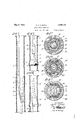
- Fig. 1 illustrates the device provided by this invention mounted on the lower end of an operating string in a well bore and carrying a fishing tool in engagement with a fish.
- Fig. 2 shows the invention carried on the lower end of an operating string and operating a well drilling tool. a well drilling tool being deflected by a whipstock into the cut made by the tool illustrated in Fig. 2 of the drawings.
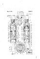
- Fig. 3 is anenlarged longitudinal detailed sectional view of the device showing the parts in the normal or 4unactuated positions.
- Fig. 4 is a view similar to Fig. 3 showing the parts in the actuated positions.
- -Figs. 5, 6, 7 and 8 are enlarged transverse' detailed sectional views taken as indicated by lines 5 5, 6 6, 7 7 and 8 8 respectively, on Fig. 3.
- Fig.- 9 isv a verticalv sectional view of the bearing included in the present invention, and
- Fig. 10 isa bottom elevation of the bearing, being a view taken as indicated by lines 10 10 on Fig. 9.
- Thetool or device provided ⁇ by my inven-.
- tion may be used in numerous situations and 1n connection with various well drilling operations, for example, it may be employed in ishing operations, in the side-tracking of a 'drill tool from a well bore, and may carry a wall hook, a socket, a grab, a tap, a drill collar, or any other form of iishing tool', as well as drillingtools of various characters, casing cutters,'etc.
- a single typical embodiment and two uses or applications of the invention will be described. It is to be understood, however, that the invention is not to be taken as llmlted or restricted to the speciic form or applications about to be described, but vis to be taken as including any-features or modiications that my fall within the scope of the claims.
- the device of the present invention includes, generally, a body 1Q adapted to be at- 50 tached tothe lower end of an operating string S of drill pipe, a stem 11 for carrying a tool T and pro]ecting from and tiltably connected with the body 10.,.a piston 12 operable in the body7 by fluidpressure, and an operative connection 13 between the piston 12 and the tilt- I able tool carrying stein 11 whereby operation o'f the piston 12 tilts or operates the stem.
- the body 1 0 is a tubular structure carrying and encaslng the piston 12 and the other principal parts of the device.
- the body 10 is preferably sectional, comprising an upper se'ction'14 and a lower section 15.
- the upper section 14 of the body is tubular, having a central longitudinal opening 16 and is provided at its upper end with suitable means for connection with the operating string S.
- Fig. 2a illustrates l
- a' tapered'screw-threaded socket 17 is provided in the upper end of the section 14 to receive the pin 18 of a tooljoint section
- a threaded pin 20 is provided on the lower end of the upper section 14 to thread into a socket 21 in the upper end of the section 15.
- the stem 11 is an elongated member hav- A ing a central longitudinal fluid passage 22.
- the upper end of the stem 11 extends into the lower end of the body section 15, while the lower end of the stem 11 is connected with the tool T.
- the passage 22 operates to pass Huid from the interior of the body lOto the tool T.
- a tapered screw-threaded pin 23, or the like may be provided on the lower end of the stem 11 to facilitate the connection of the stem with the tool T.
- a tilting connection is provided between the body 10 and the stem 11 whereby the stem is movable from thenormal position illustrated in Fig. 3 of the drawings to the actuated position illustrated in Fig. 4 of the drawings.
- Thetilting or tiltable connection be ⁇ tween the stem 11 and-the body includes a rounded or spherical enlargement 24 on the stem 11 and a seat- 25 in the body 10 for carry-A ing the spherical enlargement 24.
- the rounded enlargement is integral with the stem 11 and is provided'fadjacent the upper end of the stem.
- the seat 25 is provided in the wall of the opening 19 adjacent the lower end of the body and is concave to effectively cooperate with the ball or enlargement 24.
- the enlargement 24 fits the seat 25 so that the stem 11 is free to tilt or oscillate about an axis Y and its inner side is concave and shaped to effectively seal with the ballor enlargement 24.
- Ther packing 26 is compressed or acted upon by theizid under pressure in the opening 19 to tightly seal with the enlargement 24 and with the walls of the groove 27.V
- An annular groove 28 is provided in the upper end of the packing 26 to allow the Huid pressure to force the packing against the ball enlargement 24 and against the Walls of the groove 27. It is referred to make the groove 28 of substantial y V shaped cross section, as clearly illustrated throughout the drawings.
- the packing 26 in sealing between the enlargement 24 and the body, prevents solid matter or sediment .from interfering with the free movement ofthe stem 11. Drain openings 29 may be provided in the stem 11 to allow any sediment'that may settle in the body to pass into the fluid passage 22.
- the stem 11 is prevented from rotating relative to the' body and is adapted to project from only one side of the body.
- Lugs og: projections 30 are provided at diametrically opposite points on the stem 11.
- the projections 30 are provided on the stem on the upper end ofthe spherical enlargement 24, and have at vertiwall of the body opening 19 immediately be- ⁇ removably clamped between cal outer sides.
- the outer sides of the vpro- ]ections 30 cooperate with flat vertical faces 31 provided on the walls of the opening 19.”
- the piston 12 is slidable in the opening 15 of the upper body section 14 'and is operable downwardly /by uid unde r pressure to cause the actuation or tilting of the stem 11.
- the piston 12 includes a mandrel or rod 34 and a sealing member or cupleather 35 for sealing with the walls Aof the open- 16.
- the rod v34 is guided for central ve ⁇ cal movement by the bearing 36.
- the Vbearing 36 may be ⁇ A the lower end of the in 20 and/the bottom of the socket 21.
- a suita le bushing 37 may be provided in the bearing 36 to slidablyfpass and guide the rod 34.
- Spaced vertical openings 38 are provided, in the lbearing 36 to pnt the.
- the cupleather 35 is mounted on the rod 34 between a block 38 and a nut 3') screw-threaded on the upper en'd of the rod.
- a suitable washer-,40 may be provided 'between the nut 3 9 and the cupleather 35'.' The' cupleather 35 is such that pressure on the Huid above the piston is eiective in operating the piston downwardly.
- the pis- ⁇ ton rod 34 is tubular, having a central longitudinal Huid passage 41 extending thro h it from one end to the other.
- An or' ce plate 42 is arranged across theV passage 41 and has a comparatively small orifice or opening 43.
- the orifice plate 42 may be removably retained in position by a tubular up on the Huid in the operating string S so that the piston 12 is ⁇ operable downwardly when pressure is puton the circulation fluid in the string. It is preferred to form the orifice plate 42 of cast iron orl other friable or frangible material ⁇ so that it may .be
- the orifice plate 42 may be broken out in various manners, for example, an object such as a steel ball or the .like may be passed into the operating string S to close the orifice 43, and high presspre may be put onthe fluid in the operating string to break out the plate.
- the operative connection 13 between the piston 12 and the stem 11 is in the nature of a wedge or cam means operable to cause tilting of the stem 11 upon downward movement of the piston 12.
- the operative connection 13 includes a wedge or cam part 45 on the lower end of therod 34 and a head 46 on the upper end of the stem 11.
- the cam part 45w is in the nature of an enlargement on the piston rod 34 below the bearing 36.
- An inclined wedge or cam face 47 is provided on the lower end of the cam part 45.
- the face 47 maf,T be flat and may occupy the entire lower end of the cam part 45.
- Flat vertical faces 48 are provided at diametrically opposite sides of the cam part 45.
- The; faces 48 ⁇ slidably cooperate with vertical plates 49 to hold the cam part ⁇ 45 and the piston 12 against turning or rotating 1n the body.
- the plates49 are comparatively long andare seated in verticalkeyways or groovesk 50 in th walls of the body opening 19.
- the faces 31 are the inner walls of the grooves 50.
- the plates also operate-to hold the stem l against upwardV movement.
- the inne? ends p of theplates extend into notches '36"l 1n the bearing 36 while the lower ends of' the plates engage the ⁇ upper ends of the lugsl 3,0.
- Theupper ends of the lugs 30 are latto effectively cooperate with the ends of the plates" 49.
- the upper corners of the lugs 30 are beveled or rounded to allow the stem to rotate. y
- the head 46 may be in the nature ofan in,- tegral .projection on the upper end of the stem 11 above the spherical enlargementI 24.
- thevcam face v47 is beveled or inclined downwardly and outwardly.
- An anti-friction roller 52 is rotatably mounted on the head 46 to project from the beveled corner 51.
- the cam face 37 is adapted to cooperate with the anti-friction vroller 52 upon operation of the piston 12.
- Flat vertical faces 53 may be provided at diametrically opposite sides of the head 46 to slidably engage the plates 49 to assist the projections 30 in holdingr the stem l1 against rotation relative to the body 10.
- the axis of the tilting movement'of the In ⁇ employing the device provided by this invention, the body 10 may be attached to the lower end of the operating string S in the manner illustrated throughout the drawinns toctlie lower end of the tiltable stem 11.
- the device and the tool -T may be passed into the well with the parts in the positions illus- "trated in Fig. Sof the drawings. When the tool T is in the desired position in the well bore, pressure or increased pressure is applied to the fluid in the. operating string S to cause the downward movement of the piston 12.
- the point of contact beween the roller 52 and' the cam face 47 is spaced from the axis of movement of the stem 11 so that the necessary leverage-is obtained to swing or tilt the lower projecting end of the stem outwardly.
- the operatingstring may be manipulated as. desired or found necessary, to carry out the operations with thetool T.
- the stem 11 when the stem 11 is in4 the inclined or off-set position illustrated in Fig. 4 of the drawings, that the projections 30 and the faces S1 l cooperate ⁇ with parts on the body 10 to positively hold the stem 11 against turning with respect to thebody.
- the operating string S may be rotated or turned if desired to rotate the tool T.
- Pressure may be maintained on the fluid in the operating stringV during and the well tool T may be attached the manipulation or operation of the tool T so that the stem 11 is tightly held in its inclined position and has no tendency to shift or move relative to the body 10.
- the face 54 of the stem forms an effective abutment for cooperating with the interiorjof the body and positively of the stem.
- thel orifice plate 42 may be fractured or broken out.
- a steel ball or other suitable object may be dropped into the operating string S to come to rest onthe orifice plate and close the opening43. Heavy orincreased pressure may then be put on thefluid in the operating string to fracture the friable disc 42.
- the device provided by the present invention may be employed in various situations, and may be .used to carry various types of well tools.
- Figs. 1 to 2a inclusive of the drawings I' have illustrated two typical uses or applications of the invention. .In 1 of the drawings, the device provided by my invention is shown mounted on ⁇ the lower end of an operating string S of drill pipe.
- A'fishin'g tooll in the form of a wall hook 60 is attached to the lower end of the tiltable stem 11.
- a fish F in the form of a broken ofi' portion of a string of pipe A1s illustrated resting against the wallof operating string the fishing tool 60 maybe passed wardly into the welly bore with the .parts of the device in the normal or unactuated positions. After the string is lowered to a point where the fishing tool or wall hook 60 is ad jacent the fish F, pressure is put on the fiuld the well bore W.
- the string S is manipulated or operated to bring the fishlng tool .6() into' gripping the fish F. It will be apparent how the fishing tool 60 being in an inclined or off-set osition in relation to the fishing str1ng 1s capable of engaging a lost object that 1s Ilying against the wall of the well whleh would be inaccessible to a fishing tool carried and operated -in the usual manner.
- the operating string S ell bore to remove the fish-F.
- Fig. 24k of the illustrates a tool 72 deflected by a whip-stock 73.
- the I whip-stock 7 3 dellects the drilling tool "i0 to extend into the enlargement made by the tool 70 and to mit into the formation at the shoulder 7L v
- the provision of the shoulder 71 in the well bore facilitates theside-tracking of the tool 72 to cut laterally vto the formation at the side o the Well bore
- the application or uses of the present invention illtrated in Figs. 1, 2 and 2a of, 2G thedrawings areto betaken asxuerelytypical examples of the uses of the invention and arenottobetaken asrestricting or confining its range of or use.
- umthestnng,atoolcarryying Ak priofrom the lower end of the body, a ball and socket connection the #ein and the lmdywlereby the stun is tiltabll, Eithae a ui p thesai n m., the swarm aan actuated means fortilting the stem.
- a device for use on a string of drill pipe including, a body to be mounted on the string, a tool stem projecting from the lower end of the body, means tiltably connecting the stem with the body including a seat in the body, a spherical part on the l stem cooperating with the seat, and packing means for sealing with said l.part above the seat, and ⁇ fluid pressure actuated means for tilting 4the Stem.
- Adeviceforuseonastringofdrill pipe including, a body to be mounted on the string,atool fr; Stemproj from the lower um body, mcamismtgiltably connecting the stem with the body'including a seat in the body, a spherical part on the stem cooperating with the seat, and means for holding the stein against rotation relative to the body, and means for tilting the stem.
- a device for use on a string of drill pipe including a tubular body attached to and having-- its interior in communication with the string, a tool carrying stem projecting from the lower end, a connection between the stem and 'the body whereby the stem is tiltable, there a fluid paage through the connection and the stem and means for tilting the stem including, a tubu' lar piston in the body operable by fluid ⁇ under p in the string, and an operative connection between the piston andstem.
- 8S. A. device for use on a string of drill pipe, including a tubular body attached to and its'interior in communication with the string, a tool stem ltably con- ⁇ nected with the body and projecting from and means for tilting piston on the body opprmure in the string,
- a device ⁇ for use on a ring of drill pipe including a tubular body attached to and having its interior in communication with the string, a tool r stem tilta'bly. with the body and projecting from the lower end thereof, and means for tilting the stem including, a p ,n on the body operable byizid under pressure in the string, there being a longitudinal fluid in the piston, a angible orifice plate restrict ing said ge, and means operatively connecting e piston and stem.
- 10.Adeviceforuseonastringoflrlrillv pipe including a tubular body attached vto the stem including, a 11o erable by Huid under and im interior 1n communication 130 I with the string, a tool carrying stem tiltably connected with the body and projecting from the lower end thereof, and means for tilting the stem including, a piston on the body operable by fluid under pressure in the string, there'being a longitudinal fluid passage in the piston, an orifice plate in the said uid passage, and an operative connection between the piston and stem, there being a fluid passage in the stem for passing fluid from the body tothe tool.
- a device for use on a string of drill pipe including a body to be mounted on the lower'end of the string, nected with the bod and projecting from the lower end of the body, a piston operable downwardly in the body, the piston having a longitudinal fluid passage, an orifice plate restricting said passage, and cam means operatively connecting piston and stem whereby operation of the piston tilts the stem, there being passing fluid from the body toa tool on the a fluid passage in the stem for stem.
- a device for use pipe including a connected with the lower end of the string, a stem projecting from the lower end of the body and adapted to carry a tool,'means for pivotally connectin the stem to the body including a seat in the ody, and a spherical part on the stem cooperating with the seat, v
Landscapes
- Life Sciences & Earth Sciences (AREA)
- Engineering & Computer Science (AREA)
- Geology (AREA)
- Mining & Mineral Resources (AREA)
- Marine Sciences & Fisheries (AREA)
- Physics & Mathematics (AREA)
- Environmental & Geological Engineering (AREA)
- Fluid Mechanics (AREA)
- General Life Sciences & Earth Sciences (AREA)
- Geochemistry & Mineralogy (AREA)
- Earth Drilling (AREA)
Description
r May y 1933.
D. 4 J. 'OGRADY DRILL STRING GOUPLING 2 Sheets-Sheet 1 Filed oct, 2:0, 1951 May 9, 19
D. J. O GRADY I DRILL STRING COUPLING Filed Oct. 20, 1931 2 Sheets-Shea?,l 2
www A Patented May 9, 1933 PATE-Nr OFFICE DRILL STRING coUrLINe Application led October 20, 1931. Serial No. 569,900.
This invention relates to a ywell tool and relates more particularly to a device for use in fishing operations, the side-tracking of drilling tools and'other well drilling opera- 5 tions,
A general object of the invention is to provide a simple, practical and effective tool carrying device adapted to be attachedl to the lower end of a string of drill pipe, or
i5' the like. and that is operable to-move the tool which it carries out of vertical or longitudinal alignment with the operating string and to hold it in that position.
Considerable dijiiculty is sometimes en- Y l5 countered in fishing or removing a lost part from a well, due 'to the fact that the fish is against the wall of the well bore, or is in a position where the fishing tool attached to the operating string inthe usual manner can- L not be brought into proper engagement with it. It is the usual practice to rigidly attach a fishing tool to the lower end of the operating string in' vertical or longitudinal alignment with the string. When the lost part 55 or fish is lying against the side wall of the well bore or is out of alignment with the operatingstring, it becomes very dicult to` bring the fishing tool into ripping and holdr3 lng engagement with the sh desirable to make an enlargement or to provide an upwardly facing shoulder in the well bore. When side-tracking a drilling tool for example, it may be necessary to cut a shoul- 33 der or enlargement in the walls of the well bore to cause the drilling tool to readily cut laterally into the formation when deflected f by the whip stock.
An objectv of the present invention is to 43 provide a 4device for attaching or lconnecting a fishing tool, a drilling tool, or the like, to the lower end of an operating string, that is operable to move the tool to an off-'set and inclined position with respectfto the operat- 45 ing string and to hold the tool in the off-set and inclined position duringV the operation of the tool.
Another object of the inventionv is to provide a device of the character mentioned that 5'3 is operated hydraulically, that is, it is oper- Inv certain well drilling operations, it is ated or controlled by varying the pressure on the circulation Huid in the operating string.- The tool provided by thisinvention may be passed into the Well on the lower end of an operating string in the normal or unactuated position Where it carries a tool in longitudinal alignment with the string, and may be operated when yin any desired position1 in the well to-move the tool to the Oifsct and inclined position by putting pressure or increased pressure' on the circulation Huid l'in the operating string.
Another object of the invention' is to provide a tool'carrying a device of the character i mentioned that is positive in operation land that is simple and sturdy in construction. The device provided by the present invention does not embody any springs, hinge pins, l
screws, or the like, that might be subject to v failure, or to become made inoperative by the presence of mud eor solid matter in the device.
Another object of the invention is to provide a device of the character mentioned that permits the continuous circulation of fluid thr ugh the operating string and tool. After act ation of the device, afull or ample circulation of fluid may be maintained through the operating string of drill pipe and the device.
Another object of the' invention is to provide a tool carrying device of the character mentioned that is operable to transmit a turning or rotary motion from the operating string to the tool. The device is constructed -so that the tool may be turned to any desired position in the well bore or may be rotated 1f desired.
Another object of the invention is to proc n o u 0 vide a devlce of the character mentloned 1n which the 1 tiltable, connection between the bo(dy of the device 4and the tool carrying element is protected by an improved packing means that prevents sediment or solid matter from reaching the working parts of the connection, and prevents the leakage of circulation of fluid from the connection. y
Further objects and features of the invention will be best and. more 4fully understood from the following detailed description of a v'typical form vand application of the invention, throughout which description reference will be had to the accompanying drawings, in
which:
Fig. 1 illustrates the device provided by this invention mounted on the lower end of an operating string in a well bore and carrying a fishing tool in engagement with a fish. Fig. 2 shows the invention carried on the lower end of an operating string and operating a well drilling tool. a well drilling tool being deflected by a whipstock into the cut made by the tool illustrated in Fig. 2 of the drawings. Fig. 3 is anenlarged longitudinal detailed sectional view of the device showing the parts in the normal or 4unactuated positions. Fig. 4 is a view similar to Fig. 3 showing the parts in the actuated positions. -Figs. 5, 6, 7 and 8 are enlarged transverse' detailed sectional views taken as indicated by lines 5 5, 6 6, 7 7 and 8 8 respectively, on Fig. 3. Fig.- 9 isv a verticalv sectional view of the bearing included in the present invention, and Fig. 10 isa bottom elevation of the bearing, being a view taken as indicated by lines 10 10 on Fig. 9.
Thetool or device provided `by my inven-.
tionmay be used in numerous situations and 1n connection with various well drilling operations, for example, it may be employed in ishing operations, in the side-tracking of a 'drill tool from a well bore, and may carry a wall hook, a socket, a grab, a tap, a drill collar, or any other form of iishing tool', as well as drillingtools of various characters, casing cutters,'etc. Throughoutthe following detailed disclosure, a single typical embodiment and two uses or applications of the invention will be described. It is to be understood, however, that the invention is not to be taken as llmlted or restricted to the speciic form or applications about to be described, but vis to be taken as including any-features or modiications that my fall within the scope of the claims.
The device of the present invention includes, generally, a body 1Q adapted to be at- 50 tached tothe lower end of an operating string S of drill pipe, a stem 11 for carrying a tool T and pro]ecting from and tiltably connected with the body 10.,.a piston 12 operable in the body7 by fluidpressure, and an operative connection 13 between the piston 12 and the tilt- I able tool carrying stein 11 whereby operation o'f the piston 12 tilts or operates the stem. i The body 1 0 is a tubular structure carrying and encaslng the piston 12 and the other principal parts of the device.- The body 10 is preferably sectional, comprising an upper se'ction'14 and a lower section 15. The upper section 14 of the body is tubular, having a central longitudinal opening 16 and is provided at its upper end with suitable means for connection with the operating string S.
Fig. 2a illustrates l In the particular case illustrated in the drawings, a' tapered'screw-threaded socket 17 is provided in the upper end of the section 14 to receive the pin 18 of a tooljoint section,
'or the like, on the lower end ofthe operating connection is provided between the sections 14 and 15. In the specific form of the invention illustrated in the drawings, a threaded pin 20 is provided on the lower end of the upper section 14 to thread into a socket 21 in the upper end of the section 15.
The stem 11 is an elongated member hav- A ing a central longitudinal fluid passage 22. The upper end of the stem 11 extends into the lower end of the body section 15, while the lower end of the stem 11 is connected with the tool T. The passage 22 operates to pass Huid from the interior of the body lOto the tool T. A tapered screw-threaded pin 23, or the like may be provided on the lower end of the stem 11 to facilitate the connection of the stem with the tool T.
A tilting connection is provided between the body 10 and the stem 11 whereby the stem is movable from thenormal position illustrated in Fig. 3 of the drawings to the actuated position illustrated in Fig. 4 of the drawings. Thetilting or tiltable connection be` tween the stem 11 and-the body includes a rounded or spherical enlargement 24 on the stem 11 and a seat- 25 in the body 10 for carry-A ing the spherical enlargement 24. The rounded enlargement is integral with the stem 11 and is provided'fadjacent the upper end of the stem. The seat 25 is provided in the wall of the opening 19 adjacent the lower end of the body and is concave to effectively cooperate with the ball or enlargement 24. The enlargement 24 fits the seat 25 so that the stem 11 is free to tilt or oscillate about an axis Y and its inner side is concave and shaped to effectively seal with the ballor enlargement 24. Ther packing 26 is compressed or acted upon by the luid under pressure in the opening 19 to tightly seal with the enlargement 24 and with the walls of the groove 27.V An annular groove 28 is provided in the upper end of the packing 26 to allow the Huid pressure to force the packing against the ball enlargement 24 and against the Walls of the groove 27. It is referred to make the groove 28 of substantial y V shaped cross section, as clearly illustrated throughout the drawings. The packing 26 in sealing between the enlargement 24 and the body, prevents solid matter or sediment .from interfering with the free movement ofthe stem 11. Drain openings 29 may be provided in the stem 11 to allow any sediment'that may settle in the body to pass into the fluid passage 22.
In the preferred construction, the stem 11 is prevented from rotating relative to the' body and is adapted to project from only one side of the body. Lugs og: projections 30 are provided at diametrically opposite points on the stem 11. The projections 30 are provided on the stem on the upper end ofthe spherical enlargement 24, and have at vertiwall of the body opening 19 immediately be-` removably clamped between cal outer sides. The outer sides of the vpro- ]ections 30cooperate with flat vertical faces 31 provided on the walls of the opening 19."
The cooperation of the projections 30 with the faces 31, holds the stem 11 against rotation relative to the body 10 and permits tilting of the stem about a transverse axis. r1`he stem 11 is chamfered or cut away immediately below the enlargement 24 as at 32. The
low the seat 25 and passing the cutaway portion 32 of the body is Hared outwardly and downwardly .as lillustrated at 33. The cutaway portions 32 and 33 permit the stem to tilt outwardly and upwardly to the position illustrated in Fig. 4 of the drawings. r
The piston 12 is slidable in the opening 15 of the upper body section 14 'and is operable downwardly /by uid unde r pressure to cause the actuation or tilting of the stem 11. The piston 12 includes a mandrel or rod 34 and a sealing member or cupleather 35 for sealing with the walls Aof the open- 16. The rod v34 is guided for central ve `cal movement by the bearing 36. The Vbearing 36 may be` A the lower end of the in 20 and/the bottom of the socket 21. A suita le bushing 37 may be provided in the bearing 36 to slidablyfpass and guide the rod 34. Spaced vertical openings 38 are provided, in the lbearing 36 to pnt the. opening 16 in communication with the opening 19 so that back pressure Y cannot develop below the piston 12. The cupleather 35 is mounted on the rod 34 between a block 38 and a nut 3') screw-threaded on the upper en'd of the rod. A suitable washer-,40 may be provided 'between the nut 3 9 and the cupleather 35'.' The' cupleather 35 is such that pressure on the Huid above the piston is eiective in operating the piston downwardly.
In accordance with the invention, the pis-` ton rod 34 is tubular, having a central longitudinal Huid passage 41 extending thro h it from one end to the other. An or' ce plate 42 is arranged across theV passage 41 and has a comparatively small orifice or opening 43. The orifice plate 42 may be removably retained in position by a tubular up on the Huid in the operating string S so that the piston 12 is` operable downwardly when pressure is puton the circulation fluid in the string. It is preferred to form the orifice plate 42 of cast iron orl other friable or frangible material `so that it may .be
broken out if desired. The orifice plate 42 may be broken out in various manners, for example, an object such as a steel ball or the .like may be passed into the operating string S to close the orifice 43, and high presspre may be put onthe fluid in the operating string to break out the plate. I
The operative connection 13 between the piston 12 and the stem 11 is in the nature of a wedge or cam means operable to cause tilting of the stem 11 upon downward movement of the piston 12. The operative connection 13 includes a wedge or cam part 45 on the lower end of therod 34 and a head 46 on the upper end of the stem 11. The cam part 45wis in the nature of an enlargement on the piston rod 34 below the bearing 36. An inclined wedge or cam face 47 is provided on the lower end of the cam part 45. The face 47 maf,T be flat and may occupy the entire lower end of the cam part 45.
Flat vertical faces 48 are provided at diametrically opposite sides of the cam part 45. The; faces 48` slidably cooperate with vertical plates 49 to hold the cam part` 45 and the piston 12 against turning or rotating 1n the body. The plates49 are comparatively long andare seated in verticalkeyways or groovesk 50 in th walls of the body opening 19. The faces 31 are the inner walls of the grooves 50. The plates also operate-to hold the stem l against upwardV movement. The inne? ends p of theplates extend into notches '36"l 1n the bearing 36 while the lower ends of' the plates engage the` upper ends of the lugsl 3,0. Theupper ends of the lugs 30 are latto effectively cooperate with the ends of the plates" 49. The upper corners of the lugs 30 are beveled or rounded to allow the stem to rotate. y
. The head 46 may be in the nature ofan in,- tegral .projection on the upper end of the stem 11 above the spherical enlargementI 24.
The upper corner 51 ofthe head 46 opposing ment of the stem.
thevcam face v47 is beveled or inclined downwardly and outwardly. An anti-friction roller 52 is rotatably mounted on the head 46 to project from the beveled corner 51.
The cam face 37 is adapted to cooperate with the anti-friction vroller 52 upon operation of the piston 12. Flat vertical faces 53 may be provided at diametrically opposite sides of the head 46 to slidably engage the plates 49 to assist the projections 30 in holdingr the stem l1 against rotation relative to the body 10. The axis of the tilting movement'of the In `employing the device provided by this invention, the body 10 may be attached to the lower end of the operating string S in the manner illustrated throughout the drawinns toctlie lower end of the tiltable stem 11. The device and the tool -T may be passed into the well with the parts in the positions illus- "trated in Fig. Sof the drawings. When the tool T is in the desired position in the well bore, pressure or increased pressure is applied to the fluid in the. operating string S to cause the downward movement of the piston 12. It will be apparent how the orifice plate 42, in restricting the fiuid passage 41,
provides a differential in pressure at opposite sides'of the piston so ,thatpressure on 4 of the drawings.
fluid above the piston lcauses the downward operation of the piston. Downward movement of the piston 12 causes thecam face 47 to cooperate with the roller 52 to move or tilt the stem 11 from the normal vertical posit1on to the tilted position illustrated in Fig.
It is to be noted that the point of contact beween the roller 52 and' the cam face 47 is spaced from the axis of movement of the stem 11 so that the necessary leverage-is obtained to swing or tilt the lower projecting end of the stem outwardly. A fter the stem hasbeen operated to the incllned or off-set position in the manner described above, the operatingstring may be manipulated as. desired or found necessary, to carry out the operations with thetool T.
It is to be notedthat when the stem 11 is in4 the inclined or off-set position illustrated in Fig. 4 of the drawings, that the projections 30 and the faces S1 l cooperate\with parts on the body 10 to positively hold the stem 11 against turning with respect to thebody. Due to this construction, the operating string S may be rotated or turned if desired to rotate the tool T. Pressure may be maintained on the fluid in the operating stringV during and the well tool T may be attached the manipulation or operation of the tool T so that the stem 11 is tightly held in its inclined position and has no tendency to shift or move relative to the body 10. The face 54 of the stem forms an effective abutment for cooperating with the interiorjof the body and positively of the stem. If after operation of the device it is desired to maintain or provide full circulation of fluid through the device, thel orifice plate 42 may be fractured or broken out. A steel ball or other suitable object may be dropped into the operating string S to come to rest onthe orifice plate and close the opening43. Heavy orincreased pressure may then be put on thefluid in the operating string to fracture the friable disc 42. The device provided by the present invention may be employed in various situations, and may be .used to carry various types of well tools. In Figs. 1 to 2a inclusive of the drawings, I' have illustrated two typical uses or applications of the invention. .In 1 of the drawings, the device provided by my invention is shown mounted on `the lower end of an operating string S of drill pipe. A'fishin'g tooll in the form of a wall hook 60 is attached to the lower end of the tiltable stem 11. A fish F in the form of a broken ofi' portion of a string of pipe A1s illustrated resting against the wallof operating string the fishing tool 60 maybe passed wardly into the welly bore with the .parts of the device in the normal or unactuated positions. After the string is lowered to a point where the fishing tool or wall hook 60 is ad jacent the fish F, pressure is put on the fiuld the well bore W. The
in the operating string to operate the piston 12 downwardly and cause tilting of the stem 11. Tilting of the stem 11 throws or moves the fishing tool 60 to the inclined posltion illustrated in the drawings. After actuation of the device, the string S is manipulated or operated to bring the fishlng tool .6() into' gripping the fish F. It will be apparent how the fishing tool 60 being in an inclined or off-set osition in relation to the fishing str1ng 1s capable of engaging a lost object that 1s Ilying against the wall of the well whleh would be inaccessible to a fishing tool carried and operated -in the usual manner. After the fish lF is gripped by the fishing tool l60, the operating string S ell bore to remove the fish-F.
Iny Fig. 2 of the drawings I have illustrated a roller type of drilling tool attached to the lower endvof the stem 11. The tool of the present invention is attached to the lower end4 of an operating string S inthe manner described above.
is tilted and where itcarries the drillingto'ol limits the tilting movement or holding engagement with v may be withdrawn fromvthe I .The device is illustrated in the actuated position where the lstem 11- anv in an inclined position S carrying thev device, and down` m alamy vmoeurs 70 in an olf-set and inclined position. The drillingtool 70is shown cuttingan enlargement orshoulder 71 in the walls of the well bore W. It will be apparent how the drill- 5 ing tool 70 carried on the lower end of the inclined stem 11, cuts outwardly or laterally into the walls of the well bore W. Fig. 24k of the illustrates a tool 72 deflected by a whip-stock 73. lThe I whip-stock 7 3 dellects the drilling tool "i0 to extend into the enlargement made by the tool 70 and to mit into the formation at the shoulder 7L v The provision of the shoulder 71 in the well bore facilitates theside-tracking of the tool 72 to cut laterally vto the formation at the side o the Well bore The application or uses of the present invention illtrated in Figs. 1, 2 and 2a of, 2G thedrawings areto betaken asxuerelytypical examples of the uses of the invention and arenottobetaken asrestricting or confining its range of or use. p
Having dcribed only a typical preferred 25 crm of my invention, I do not wish to limit myself to the specific details set forth, but wdr to reserve to myself any or variatiom that may appear to those Skilled in art orfall within thescope of the folmy invention, I claim: L of the character dcscribeg for nseomastnn, vo pipe includm' gatu ular bodyto be attached to the lower end of the ringand adaptedtocommunicate withthe stng,a Muprojecting fromthe lower end of the body tiltably connected to the body,mea'nson i estem orcarrymg' atool, therebeingailuidpassageinthestcmfor Lfcilnidfromthebddytctlietool,iluid prmeactuatedmeansinthehodandan operative connection betweenthesaidmcans andthestemwherebysaid meansisoperable 2. A device' of tfzhe character described for 'useonastringo pipeincludlng ahlbular bodytobeattafchedtothelowerendofthe Mug, a stem or a tool and projectingfmm the lower of and cmnectedtothebody,therebeinga inthe stem for circulatingiluid from thebodyto the tool, and fluid pressure aetnatedlneansfortiltingtheem.
3. device for lise ouh:d L;A pipeincludmg' ,atuular l.'
umthestnng,atoolcarryying Ak,priofrom the lower end of the body, a ball and socket connection the #ein and the lmdywlereby the stun is tiltabll, Eithae a ui p thesai n m., the swarm aan actuated means fortilting the stem.
"'LAdcviee or-use onastringofdrill pipeinclnding,abodytobemountedonthe sirmg,atodcarrymgstemfrm1 the lower end thereo ,there being s litndinnauid the lower end of the body means tiltably connecting the. sam with tte body, including a seat in the body, and a spherical part on the stem cooperating with the seat, and iiuid pressure actuated means in the body for tilting the stem.
5. A device for use on a string of drill pipe including, a body to be mounted on the string, a tool stem projecting from the lower end of the body, means tiltably connecting the stem with the body including a seat in the body, a spherical part on the l stem cooperating with the seat, and packing means for sealing with said l.part above the seat, and` fluid pressure actuated means for tilting 4the Stem.
G Adeviceforuseonastringofdrill pipe including, a body to be mounted on the string,atool fr; Stemproj from the lower um body, mcamismtgiltably connecting the stem with the body'including a seat in the body, a spherical part on the stem cooperating with the seat, and means for holding the stein against rotation relative to the body, and means for tilting the stem.
7. A device for use on a string of drill pipe, including a tubular body attached to and having-- its interior in communication with the string, a tool carrying stem projecting from the lower end, a connection between the stem and 'the body whereby the stem is tiltable, there a fluid paage through the connection and the stem and means for tilting the stem including, a tubu' lar piston in the body operable by fluid `under p in the string, and an operative connection between the piston andstem.
8S. A. device for use on a string of drill pipe, including a tubular body attached to and its'interior in communication with the string, a tool stem ltably con-` nected with the body and projecting from and means for tilting piston on the body opprmure in the string,
passage 1n the piston, an o ce plate in the said fluid passage, and an operative connection between the piston and stem.
9. A device `for use on a ring of drill pipe, including a tubular body attached to and having its interior in communication with the string, a tool r stem tilta'bly. with the body and projecting from the lower end thereof, and means for tilting the stem including, a p ,n on the body operable by luid under pressure in the string, there being a longitudinal fluid in the piston, a angible orifice plate restrict ing said ge, and means operatively connecting e piston and stem.
10.Adeviceforuseonastringoflrlrillv pipe, including a tubular body attached vto the stem including, a 11o erable by Huid under and im interior 1n communication 130 I with the string, a tool carrying stem tiltably connected with the body and projecting from the lower end thereof, and means for tilting the stem including, a piston on the body operable by fluid under pressure in the string, there'being a longitudinal fluid passage in the piston, an orifice plate in the said uid passage, and an operative connection between the piston and stem, there being a fluid passage in the stem for passing fluid from the body tothe tool.-
11. A device for use on a string of drill pipe, including a body to be mounted on the lower'end of the string, nected with the bod and projecting from the lower end of the body, a piston operable downwardly in the body, the piston having a longitudinal fluid passage, an orifice plate restricting said passage, and cam means operatively connecting piston and stem whereby operation of the piston tilts the stem, there being passing fluid from the body toa tool on the a fluid passage in the stem for stem.
12. A device for use pipe including a connected with the lower end of the string, a stem projecting from the lower end of the body and adapted to carry a tool,'means for pivotally connectin the stem to the body including a seat in the ody, and a spherical part on the stem cooperating with the seat, v
means on the body for pivoting the stem, and
means for preventingrotation of the stem including cooperating relative tothe body flat surfaces on the body and said spherical pat. e v
day of October 1931.
* DANIEL J. OGRADY.
a stem tiltably conon a string of drill I tubular'body adapted to be Witness that I claim the foregoing I A have hereuntosubscribed my name this 14th
Priority Applications (1)
| Application Number | Priority Date | Filing Date | Title |
|---|---|---|---|
| US569900A US1908174A (en) | 1931-10-20 | 1931-10-20 | Drill string coupling |
Applications Claiming Priority (1)
| Application Number | Priority Date | Filing Date | Title |
|---|---|---|---|
| US569900A US1908174A (en) | 1931-10-20 | 1931-10-20 | Drill string coupling |
Publications (1)
| Publication Number | Publication Date |
|---|---|
| US1908174A true US1908174A (en) | 1933-05-09 |
Family
ID=24277366
Family Applications (1)
| Application Number | Title | Priority Date | Filing Date |
|---|---|---|---|
| US569900A Expired - Lifetime US1908174A (en) | 1931-10-20 | 1931-10-20 | Drill string coupling |
Country Status (1)
| Country | Link |
|---|---|
| US (1) | US1908174A (en) |
Cited By (8)
| Publication number | Priority date | Publication date | Assignee | Title |
|---|---|---|---|---|
| US2504397A (en) * | 1945-12-11 | 1950-04-18 | Wilburne A Dickson | Fishing tool attachment |
| US2568060A (en) * | 1945-06-02 | 1951-09-18 | William H Dumble | Jar shoulder knuckle joint |
| US2643900A (en) * | 1950-08-24 | 1953-06-30 | Emerson L Mcbride | Knuckle joint |
| US2680483A (en) * | 1949-05-02 | 1954-06-08 | Bus Franklin L Le | Method and apparatus for recovering lost drill pipe |
| US2726881A (en) * | 1953-01-05 | 1955-12-13 | Clifford M Howard | Knuckle joint with lateral actuating means |
| US2799475A (en) * | 1953-01-08 | 1957-07-16 | Texas Co | Reaming apparatus |
| US3166350A (en) * | 1962-03-08 | 1965-01-19 | Roy R Richert | Kick-over fishing tool |
| EP3385498A1 (en) * | 2012-12-21 | 2018-10-10 | Longyear TM, Inc. | Overshot assembly and systems and methods of using same |
-
1931
- 1931-10-20 US US569900A patent/US1908174A/en not_active Expired - Lifetime
Cited By (8)
| Publication number | Priority date | Publication date | Assignee | Title |
|---|---|---|---|---|
| US2568060A (en) * | 1945-06-02 | 1951-09-18 | William H Dumble | Jar shoulder knuckle joint |
| US2504397A (en) * | 1945-12-11 | 1950-04-18 | Wilburne A Dickson | Fishing tool attachment |
| US2680483A (en) * | 1949-05-02 | 1954-06-08 | Bus Franklin L Le | Method and apparatus for recovering lost drill pipe |
| US2643900A (en) * | 1950-08-24 | 1953-06-30 | Emerson L Mcbride | Knuckle joint |
| US2726881A (en) * | 1953-01-05 | 1955-12-13 | Clifford M Howard | Knuckle joint with lateral actuating means |
| US2799475A (en) * | 1953-01-08 | 1957-07-16 | Texas Co | Reaming apparatus |
| US3166350A (en) * | 1962-03-08 | 1965-01-19 | Roy R Richert | Kick-over fishing tool |
| EP3385498A1 (en) * | 2012-12-21 | 2018-10-10 | Longyear TM, Inc. | Overshot assembly and systems and methods of using same |
Similar Documents
| Publication | Publication Date | Title |
|---|---|---|
| US6547017B1 (en) | Rotary drill bit compensating for changes in hardness of geological formations | |
| US2770444A (en) | Circulating and rotating retrievable whipstock | |
| US5267620A (en) | Drilling latch apparatus | |
| US2834578A (en) | Reamer | |
| US1908174A (en) | Drill string coupling | |
| US3220478A (en) | Casing cutter and milling tool | |
| US2857138A (en) | Core barrel | |
| US4057887A (en) | Pipe disconnecting apparatus | |
| US3752230A (en) | Pulling tool | |
| US3351144A (en) | Rotary expansible drilling apparatus with centrifugally operated latch | |
| US2290409A (en) | Means for withdrawing casing from wells or boreholes | |
| US2010587A (en) | Joint for connecting parts of well drilling and well pumping equipment | |
| US2061316A (en) | Drill hole deflector | |
| US1801456A (en) | Fishing tool | |
| US3087559A (en) | Adjustable hydraulic trip release | |
| US2922479A (en) | Apparatus for controlling fluid circulation | |
| US2662600A (en) | Well cementing plug | |
| US2489687A (en) | Drill bit | |
| US3473608A (en) | Seating and retrieving tool for wear and protective bushings in casing during rotary drilling operations | |
| US2680483A (en) | Method and apparatus for recovering lost drill pipe | |
| US2907391A (en) | Valves | |
| US2215632A (en) | Pipe cutting tool | |
| US2739653A (en) | Well tool and anchoring means therefor | |
| US2285213A (en) | Knuckle joint | |
| US2375313A (en) | Well tool |