US1908138A - Tone carrier projecting apparatus - Google Patents
Tone carrier projecting apparatus Download PDFInfo
- Publication number
- US1908138A US1908138A US406774A US40677429A US1908138A US 1908138 A US1908138 A US 1908138A US 406774 A US406774 A US 406774A US 40677429 A US40677429 A US 40677429A US 1908138 A US1908138 A US 1908138A
- Authority
- US
- United States
- Prior art keywords
- film
- disk
- light
- circuit
- motor
- Prior art date
- Legal status (The legal status is an assumption and is not a legal conclusion. Google has not performed a legal analysis and makes no representation as to the accuracy of the status listed.)
- Expired - Lifetime
Links
- 238000012360 testing method Methods 0.000 description 15
- 238000009877 rendering Methods 0.000 description 3
- XEEYBQQBJWHFJM-UHFFFAOYSA-N Iron Chemical compound [Fe] XEEYBQQBJWHFJM-UHFFFAOYSA-N 0.000 description 2
- 238000005259 measurement Methods 0.000 description 2
- 230000003287 optical effect Effects 0.000 description 2
- 101100400378 Mus musculus Marveld2 gene Proteins 0.000 description 1
- 230000005611 electricity Effects 0.000 description 1
- 229910052742 iron Inorganic materials 0.000 description 1
Images
Classifications
-
- G—PHYSICS
- G11—INFORMATION STORAGE
- G11B—INFORMATION STORAGE BASED ON RELATIVE MOVEMENT BETWEEN RECORD CARRIER AND TRANSDUCER
- G11B7/00—Recording or reproducing by optical means, e.g. recording using a thermal beam of optical radiation by modifying optical properties or the physical structure, reproducing using an optical beam at lower power by sensing optical properties; Record carriers therefor
Definitions
- My invention relates to improvements in tone carrier projecting apparatus.
- a mechanical modulation device which influences the beam of light with a known and easily measurable modulation.
- a perforated disk may, for instance, be employed which preferably electrically driven, produces a constant buzzing sound which may be measured, for instance, by a tube voltmeter.
- the starting of the perforated disk may take place automatically during the intervals in the performance.
- a contact device is then provided at a point of the path of the film and is controlled by the filmstrip. If there is no film in the guide the contact device closes the motor circuit for the drive of the perforated disk and thus starts the disk. If the test current is not intended to be audible in the loud speaker, or if it is desired to compare the sound of the loud speaker with the tone of a tuning fork,the loud speaker may be out out'of circuit by the contact device controlled by the film. In this way a continuous supervision may be carried out during intervals in the performance since it is only necessaryto watch a measuring instrument to ascertain whether the plant is working satisfactorily.
- the perforated disk In order that the perforated disk should not obstruct the beam of light during the projection of the film when it is itself stationary, it may be adapted to be swung out of the path of thebeam of light. It is also possible to construct the perforated disk of parts which are only thrown into the path of the beam by centrifugal force when the disk is revolving. A further possibility is to provide mechanical or magnetic arresting means which take care that the disk is always arrested in such a position that the path of the beam is not obstructed.
- a lens 2 which converges the rays of light and throws an image of the slot through the tone film 3 on to the photo-electric cell 4-.
- a perforated or toothed disk 5 of sheet iron is so arranged that its toothed rim crosses the path of the beam and according to the position of the teeth shuts off the beam of light or permits it to proceed.
- the toothed disk 5 is stationary, but by means of an electric motor 6 said disk may be rotated at such a speed that the frequency of the interruption of the beam corresponds with a definite musical tone, for instance the diapason.
- the current for energizing the motor which in the case illustrated by way of example is derived from a storage battery but which might, of course, be supplied by lighting mains, is controlled by a contact device 7 which in its turn is controlled by the tone film 3 in such a manner that the niptor is switched on when the film hasrun o
- the two members of the contact device 7 are elastic and tend to move into engagement with each other to close the circuit which operates the motor 6, but as long as there is a film 3 in the apparatus, such film (as shown). holds the two members of the contact device 7 apart and thus interrupts the motor-actuating circuit.
- the reproducing loud speaker .9 which is also used for the customary purpose of enabling the operator to follow or check the sound reproduction during the showing of the picture recorded on the film 3, is actuated by photo-electric currents produced by the cell 4. and reaching said loud speaker through an amplifier 10. Ifno additional parts were provided, this loud speaker would become operative whenever the end of a film is reached and the circuit of the motor 6 is closed'to rotate the disk 5 as described above.
- the operator will (at the time that no film is running) have a purely optical test or supervision by means of a measuring or indicating instrument 11 connected in the circuit of the photo-electric cell 4. He will ascertain whether the apparatus is in proper condition, by observing said instrument 11, on the scale of which there would be a fixed mark with which the pointer of the instrument will register. in the case of satisfactory operation.
- the test or supervision avail able to the operator (at the time that no film is running) will be both optical, by means of the instrument 11 as just explained, and also acoustic, by means of the loud speaker 9 which, in the absence of the relay 8, would operate every time the motor 6 is runnlng.
- a magnetic arresting device 12 has been provided in the embodiment illustrated. It will be understood, however, that it might be-replaced by a suitable mechanical arresting device.
- the beam of light is chopped up at a certain frequency by the revolving disk so that the loud speaker produces a certain tone, the clearness and strength of which.
- the disk 5 may be compared with that of a tuning fork or a buzzer. 'If desired the buzzer tone may also be made audible in the loud speaker alternately Withthe tone produced by the perforated disk.
- I may mount such disk, together with its shaft and the motor 6, upon a suitable pivot 13, and an appropriate device, such as a set screw 14, may be provided to lock these parts against swinging on the pivot 13.
- a testing arrangement for optic-electrical sound film projectors a source of light, a photo-electric cell adapted to be struck by a beam of light proceeding from said source, a rotary perforated disk arranged to intercept said beam of light between its source and said cell, means in the circuit of said cell for rendering perceptible the modulation resulting from the intermittent action of the rotating perforated disk on the beam of light, an electric motor for driving said disk, and an actuating circuit for said motor, said circuit including a contact device having two separable members arranged to engage the sound film and to be held'in circuit-breaking position by such engagement.
- a photo-electric cell means for directing a beam of light on said cell, a rotary disk arranged to intercept said beam of light intermittently before it reaches the cell, a circuit connected with said cell, said circuit including means for rendering perceptible the modulation resulting from the intermittent interception of said beam of light, an electric motor for said disk, and an actuating circuit for said motor, said actuating circuit including a contact device located in the path of the sound-film and controlled by such film.
- a testing arrangement in which the contact device of the motor-actuating circuit is arranged to interrupt said circuit when the film engages such contact device, and to close said circuit when the film is out of engagement with such device.
- a testing arrangement in which the contact device of the motor-actuating circuit consists of two members between which the sound-film is arranged to pass so as to hold them apart in a circuit-breaking position, said members coming in contact with each other when out of contact with the film.
- a testing arrangement in which the contact device of the motor-actuating circuit consists of two members tending to come in contact with each other when unrestrained, said members being arranged on opposite sides of the soundfilm path and adapted to be engaged and held in separated, circuit-breaking position by the sound-film passing between said members.
- a testing arrangement in which the beam-controlling disk, in addition to being rotatable, is movable to bring it bodily out of the path of the light.
- a testing arrangement in which there is provided, in conjunction with the rotary disk, a device which when the disk is stationary holds such disk in a position in which it rmits the free passage of the beam of lig t.
- a photo-electric cell means for directing a beam of light on said cell, a rotary disk arranged, during its rotation, to intercept said beam of light intermittently before such beam reaches the cell, means whereby, during the presence of a film in the projector, said disk will be held stationary in a position in which it permits the free passage of the beam of light, means whereby, when there is no film in the apparatus, said disk will be rotated, and a circuit associated with said photo-electric cell, said circuit including means for rendering perceptible the modulation resultin from the intermittent interception of sai beam of light.
- a testing arrangement in which the film itself controls automatically the starting and stopping of the rotation of said disk.
Landscapes
- Indication In Cameras, And Counting Of Exposures (AREA)
Description
May 9, 1933. E. GERLACH 1,908,138
TONE CARRIER PROJECTING APPARATUS Filed Nov. 13, 1929 ATTorgbIE-fs Patented May 9, 1933 UNITED STATES PATENT OFFICE ER-WIN GERLAGH, OF BERLIN-SIEMENSSTADT, GER-MANY, AS SIGNOR TO SIEMENS 8'5 HALSKE AKTIENG-ESELLSCHAFT, OF $IEMENSSTADT NEAR BERLIN, GERMANY, .A.
CORPORATION OF GERMANY Application filed November 13, 1929, Serial No. 406,774, and in Germany November 19, 1928.
I My invention relates to improvements in tone carrier projecting apparatus.
In projecting apparatus for talking motion-pictures it is frequently necessary to test or check the apparatus as regards the quality of the tone and the strength of the sound. In order to replace the estimate of the attendant by a positive measurement easily carried out, I employ in place ofthe tone carrier, as a means of producing variations, amechanical modulation device which influences the beam of light with a known and easily measurable modulation. As such an influencing device a perforated disk may, for instance, be employed which preferably electrically driven, produces a constant buzzing sound which may be measured, for instance, by a tube voltmeter. In this way a positive measurement is rendered possible and the supervision is also greatly simplified and accelerated since no film is needed for the test and it is only necessary to drive the perforated disk.
The starting of the perforated disk may take place automatically during the intervals in the performance. A contact device is then provided at a point of the path of the film and is controlled by the filmstrip. If there is no film in the guide the contact device closes the motor circuit for the drive of the perforated disk and thus starts the disk. If the test current is not intended to be audible in the loud speaker, or if it is desired to compare the sound of the loud speaker with the tone of a tuning fork,the loud speaker may be out out'of circuit by the contact device controlled by the film. In this way a continuous supervision may be carried out during intervals in the performance since it is only necessaryto watch a measuring instrument to ascertain whether the plant is working satisfactorily.
In order that the perforated disk should not obstruct the beam of light during the projection of the film when it is itself stationary, it may be adapted to be swung out of the path of thebeam of light. It is also possible to construct the perforated disk of parts which are only thrown into the path of the beam by centrifugal force when the disk is revolving. A further possibility is to provide mechanical or magnetic arresting means which take care that the disk is always arrested in such a position that the path of the beam is not obstructed.
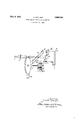
An embodiment of my invention is diagrammatically illustrated in the drawing affixed to my specification.
Referring to the single figure of the drawing it will be seen that in the beam of light emanating from the slot 1 is placed a lens 2 which converges the rays of light and throws an image of the slot through the tone film 3 on to the photo-electric cell 4-. A perforated or toothed disk 5 of sheet iron is so arranged that its toothed rim crosses the path of the beam and according to the position of the teeth shuts off the beam of light or permits it to proceed. During. the normal operation of the film, the toothed disk 5 is stationary, but by means of an electric motor 6 said disk may be rotated at such a speed that the frequency of the interruption of the beam corresponds with a definite musical tone, for instance the diapason. The current for energizing the motor which in the case illustrated by way of example is derived from a storage battery but which might, of course, be supplied by lighting mains, is controlled by a contact device 7 which in its turn is controlled by the tone film 3 in such a manner that the niptor is switched on when the film hasrun o It will be understood that the two members of the contact device 7 are elastic and tend to move into engagement with each other to close the circuit which operates the motor 6, but as long as there is a film 3 in the apparatus, such film (as shown). holds the two members of the contact device 7 apart and thus interrupts the motor-actuating circuit. When however the film runs off so thatit no longer separates the two members of the contact device 7, said members springinto engagement with each other and thus close the circuit of the battery or other source of electricity 15, to start the motor 6. The reproducing loud speaker .9, which is also used for the customary purpose of enabling the operator to follow or check the sound reproduction during the showing of the picture recorded on the film 3, is actuated by photo-electric currents produced by the cell 4. and reaching said loud speaker through an amplifier 10. Ifno additional parts were provided, this loud speaker would become operative whenever the end of a film is reached and the circuit of the motor 6 is closed'to rotate the disk 5 as described above. It may be undesirable in some cases to have the loud speaker operate at that time, and to throw it out of action automatically whenever the motor 6 is running, I may provide, in the circuit of the motor 6, a relay 8 by which the loud speaker will be thrown out of action whenever said circuit is closed. In this event the operator will (at the time that no film is running) have a purely optical test or supervision by means of a measuring or indicating instrument 11 connected in the circuit of the photo-electric cell 4. He will ascertain whether the apparatus is in proper condition, by observing said instrument 11, on the scale of which there would be a fixed mark with which the pointer of the instrument will register. in the case of satisfactory operation. If the relay 8 is omitted, then the test or supervision avail able to the operator (at the time that no film is running) will be both optical, by means of the instrument 11 as just explained, and also acoustic, by means of the loud speaker 9 which, in the absence of the relay 8, would operate every time the motor 6 is runnlng. a
In order that the perforated disk shall always stop in a position in which it does not obstruct the beam of light a magnetic arresting device 12 has been provided in the embodiment illustrated. It will be understood, however, that it might be-replaced by a suitable mechanical arresting device.
When the checking apparatus is set in operation the beam of light is chopped up at a certain frequency by the revolving disk so that the loud speaker produces a certain tone, the clearness and strength of which.
may be compared with that of a tuning fork or a buzzer. 'If desired the buzzer tone may also be made audible in the loud speaker alternately Withthe tone produced by the perforated disk. p In order to enable the disk 5 to be swung out of the path of the beam of light, I may mount such disk, together with its shaft and the motor 6, upon a suitable pivot 13, and an appropriate device, such as a set screw 14, may be provided to lock these parts against swinging on the pivot 13.
I claim as my invention:
1. In a testing arrangement for optic-electrical sound film projectors, a source of light, a photo-electric cell adapted to be struck by a beam of light proceeding from said source, a rotary perforated disk arranged to intercept said beam of light between its source and said cell, means in the circuit of said cell for rendering perceptible the modulation resulting from the intermittent action of the rotating perforated disk on the beam of light, an electric motor for driving said disk, and an actuating circuit for said motor, said circuit including a contact device having two separable members arranged to engage the sound film and to be held'in circuit-breaking position by such engagement.
2. In a testing arrangement for optic-electric sound-film projectors, a photo-electric cell, means for directing a beam of light on said cell, a rotary disk arranged to intercept said beam of light intermittently before it reaches the cell, a circuit connected with said cell, said circuit including means for rendering perceptible the modulation resulting from the intermittent interception of said beam of light, an electric motor for said disk, and an actuating circuit for said motor, said actuating circuit including a contact device located in the path of the sound-film and controlled by such film.
3. A testing arrangement according to claim 2, in which the contact device of the motor-actuating circuit is arranged to interrupt said circuit when the film engages such contact device, and to close said circuit when the film is out of engagement with such device.
4. A testing arrangement according to claim 2, in which the contact device of the motor-actuating circuit consists of two members between which the sound-film is arranged to pass so as to hold them apart in a circuit-breaking position, said members coming in contact with each other when out of contact with the film.
5. A testing arrangement according to claim 2, in which the contact device of the motor-actuating circuit consists of two members tending to come in contact with each other when unrestrained, said members being arranged on opposite sides of the soundfilm path and adapted to be engaged and held in separated, circuit-breaking position by the sound-film passing between said members.
6. A testing arrangement according to claim 2, in which the beam-controlling disk, in addition to being rotatable, is movable to bring it bodily out of the path of the light.
7 A testing arrangement according to claim 2, in which the beam-controlling disk, in addition to being rotatable, is mounted to swing away from the beam of light.
8. A testing arrangement according to claim 2, in which there is provided, in conjunction with the rotary disk, a device which when the disk is stationary holds such disk in a position in which it rmits the free passage of the beam of lig t.
9. In a testing arrangement for 0ptic-elec tric sound-film projectors, a photo-electric cell, means for directing a beam of light on said cell, a rotary disk arranged, during its rotation, to intercept said beam of light intermittently before such beam reaches the cell, means whereby, during the presence of a film in the projector, said disk will be held stationary in a position in which it permits the free passage of the beam of light, means whereby, when there is no film in the apparatus, said disk will be rotated, and a circuit associated with said photo-electric cell, said circuit including means for rendering perceptible the modulation resultin from the intermittent interception of sai beam of light.
10. A testing arrangement according to claim 9, in which the film itself controls automatically the starting and stopping of the rotation of said disk.
Intestimony whereof I afiix my signature.
ERWIN GERLACH.
Applications Claiming Priority (1)
| Application Number | Priority Date | Filing Date | Title |
|---|---|---|---|
| DE1908138X | 1928-11-19 |
Publications (1)
| Publication Number | Publication Date |
|---|---|
| US1908138A true US1908138A (en) | 1933-05-09 |
Family
ID=7748758
Family Applications (1)
| Application Number | Title | Priority Date | Filing Date |
|---|---|---|---|
| US406774A Expired - Lifetime US1908138A (en) | 1928-11-19 | 1929-11-13 | Tone carrier projecting apparatus |
Country Status (1)
| Country | Link |
|---|---|
| US (1) | US1908138A (en) |
-
1929
- 1929-11-13 US US406774A patent/US1908138A/en not_active Expired - Lifetime
Similar Documents
| Publication | Publication Date | Title |
|---|---|---|
| US2002352A (en) | Sound film apparatus | |
| US2069631A (en) | Apparatus for recording and reproducing sound | |
| US1908138A (en) | Tone carrier projecting apparatus | |
| US2159969A (en) | Appliance for testing the tension of textile threads or yarn | |
| US2378416A (en) | Combination sound and picture device | |
| US2069632A (en) | Optical sound-reproducing apparatus | |
| US2284024A (en) | Tape-actuated reproducer and light gate therefor | |
| US2042027A (en) | Sound on film reproduction | |
| US2419041A (en) | Film data projection device | |
| US2375111A (en) | Sound reproducer test method and system | |
| US2596994A (en) | Fluxmeter alarm | |
| US1564722A (en) | Apparatus for inspecting film bands | |
| US1815481A (en) | Sound recording and reproducing apparatus | |
| US745218A (en) | Combined sound-reproducing and stereopticon apparatus. | |
| SU34780A1 (en) | Chronograph sound recorder | |
| US808384A (en) | Apparatus to be used in measuring the speed of photographic shutters. | |
| US2605673A (en) | Framing light and control for motion-picture machines | |
| US1938694A (en) | Sound film recording apparatus | |
| US2437239A (en) | Film registry means for motionpicture projectors | |
| US2484322A (en) | Photographic sensitometer having an optical wedge on a rotating drum | |
| US2510607A (en) | Film sound record editing and inspection system | |
| US1477038A (en) | Camera | |
| US2285975A (en) | Sound pickup for sound film projectors | |
| US2204260A (en) | Apparatus for calibrating measuring instruments | |
| US1961372A (en) | Electrical recording |