US1908111A - Tail clamp - Google Patents
Tail clamp Download PDFInfo
- Publication number
- US1908111A US1908111A US454699A US45469930A US1908111A US 1908111 A US1908111 A US 1908111A US 454699 A US454699 A US 454699A US 45469930 A US45469930 A US 45469930A US 1908111 A US1908111 A US 1908111A
- Authority
- US
- United States
- Prior art keywords
- clamping band
- buck
- bed
- band
- free end
- Prior art date
- Legal status (The legal status is an assumption and is not a legal conclusion. Google has not performed a legal analysis and makes no representation as to the accuracy of the status listed.)
- Expired - Lifetime
Links
- 238000004804 winding Methods 0.000 description 3
- 238000010276 construction Methods 0.000 description 2
- 241000168041 Mazama Species 0.000 description 1
Images
Classifications
-
- B—PERFORMING OPERATIONS; TRANSPORTING
- B65—CONVEYING; PACKING; STORING; HANDLING THIN OR FILAMENTARY MATERIAL
- B65H—HANDLING THIN OR FILAMENTARY MATERIAL, e.g. SHEETS, WEBS, CABLES
- B65H75/00—Storing webs, tapes, or filamentary material, e.g. on reels
- B65H75/02—Cores, formers, supports, or holders for coiled, wound, or folded material, e.g. reels, spindles, bobbins, cop tubes, cans, mandrels or chucks
- B65H75/34—Cores, formers, supports, or holders for coiled, wound, or folded material, e.g. reels, spindles, bobbins, cop tubes, cans, mandrels or chucks specially adapted or mounted for storing and repeatedly paying-out and re-storing lengths of material provided for particular purposes, e.g. anchored hoses, power cables
- B65H75/38—Cores, formers, supports, or holders for coiled, wound, or folded material, e.g. reels, spindles, bobbins, cop tubes, cans, mandrels or chucks specially adapted or mounted for storing and repeatedly paying-out and re-storing lengths of material provided for particular purposes, e.g. anchored hoses, power cables involving the use of a core or former internal to, and supporting, a stored package of material
- B65H75/44—Constructional details
- B65H75/4481—Arrangements or adaptations for driving the reel or the material
- B65H75/4489—Fluid motors
-
- D—TEXTILES; PAPER
- D06—TREATMENT OF TEXTILES OR THE LIKE; LAUNDERING; FLEXIBLE MATERIALS NOT OTHERWISE PROVIDED FOR
- D06F—LAUNDERING, DRYING, IRONING, PRESSING OR FOLDING TEXTILE ARTICLES
- D06F71/00—Apparatus for hot-pressing clothes, linen or other textile articles, i.e. wherein there is substantially no relative movement between pressing element and article while pressure is being applied to the article; Similar machines for cold-pressing clothes, linen or other textile articles
- D06F71/32—Details
- D06F71/40—Holders or stretchers for the article to be pressed
Definitions
- My invention contemplates the provision of a tail clamp embodying a fiexible band that is normally disposed on one side of the buck in the smallest possible space together with mechanism for projecting the flexible band laterally across the buck and the work thereon and then drawing the band downwardly towards the buck with the least possible longi tudinal movement of the band to clamp the work on the buck. It also contemplates the provision of means for drawing the band downwardly towards the buck of such nature that the device automatically adjusts itself to work of various thicknesses thereon.
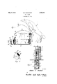
- Fig. 1 is a side view partly in section, of one embodiment of my invention in combination with a part of the pressing machine that is diagrammatically shown;
- Fig. 2 is a side elevation of the device but showing the device and operating parts as ⁇ being enclosed in a housing; and
- Fig. 3 is a view of the tail clamp and tail clamp housing.
- a pressing machine which may be of any ordinary type and which consists of the usual pressing table 1, buck 2, and a pressing head 3 that is mounted on the' end of a supporting arm 4 which is pivotally mounted and adapted to be swung by suitable means about its pivot to bring the head 3 into and out of pressing engagement with the buck 2.
- a tail clamping device consisting of a flexible band 5 that is normally disposed in a roll about a shaft or centralcore 6 journalled in a housing 7, the housing also covering the roll made up of the flexible band 5 and being suitably supported on the table l by any well known means and, in this instance, by uprights 8 secured to the table at one of their ends.
- the pinion gear 9 is rigidly mounted on the shaft 6 and disposed within a housing 10 in which the shaft 6 is also journalled.
- This pinion gear meshes with another and larger gear 11 mounted on a shaft 12 that is also Journalled in the housing 10, this housing being suitably supported on the table 1, as for instance, by means of the uprights 18.
- the shaft 12 also carries a gear 14 the purpose of which will be hereinafter apparent.
- the operating means for these gears just described embodies a single stroke piston 15 disposed within a cylinder 1G and adapted to be moved in one direction by air pressure admitted to the cylinder through the conduit 17 and in the opposite direction by means of a spring 18 disposed between the upper surface of the piston l5 and the inner surface of the upright end of the cylinder 16.
- the piston rod 19 that forms a part of the piston 15 takes, the form of a rack 20, it having gear teeth disposed thereon for a portion of its length.
- This rack 2() is so disposed as to mesh with the gear 14 whereby upward or downward movement of the piston 1,5 and rack 20 will cause rotation of the gears 9, 11 and 12 and a consequent unwinding or winding up of the flexible band 5 depending on the direction of movement of the piston and rack.
- the relative size of the gears 9, 11 and 12 may be varied as desired to change the speed of rotation of the shaft or central bore 6 about which the clamping band is normally disposed in rolled position.
- Air pressure is supplied to the cylinder 16 by way of the conduit 17, as hereinbeforc stated, which conduit leads from a valve 21 having an operating handle 22 in suoli posi-V tion as to be convenient to the operator of the press and embodying an air inlet or supply pipe 23 and an exhaust conduit 241.
- l have provided a cylinder and piston construction at the opposite side of the buck from the cylinder and piston construction just described and embodying a cylinder 25 yand piston 26 that@ is adapted to be moved in one direction in the cylinder simulta neously with movement of the piston 15 by reasonof air pressure being suppliedl to both cylinders from the same line 17 and in the opposite directionfby means of a spring 27 that is disposed between the upper surface of the piston and the under surface of the upper end ofthe cylinder 25.
- the pistonrod 28- whichV forms apart.
- piston 26 projects upwardly through the table l and is providedon its upper yend withasuitable means 29 'that may,as inA this instance, take the form of a pivoted arm c arrying a pin for engaging with anV opening or a single one of a plurality of openings inthe outer. end BG of the clamping band 5 and securing the free end of the band.
- pistons 15 and 26 will be simultaneously operatedsince they both receive air pressure from the line 11' which ⁇ supply of air pressure is controlled by the same valve 21.
- the lowermost rear edge of they pressing head 3 is provided ⁇ with approjection or; guidefl that exten-ds rearwardly and provides a guide means for.
- the work to be pressed is first placed-upon the buck 2 whereupon the operating handle 22 of the valve-21 is so moved as to supply air pressure from.v the pipe23 to the conduit 17 and thereby to the cylinders 25'and 16.
- airr pressure will simultaneously move the pistons 15 and 26 upwardly, the upward movement of the pistonl causing. rotation of the ⁇ gears 9, 11 and 12 in the manner hereinbefore described and rotation of the shaft 6 to cause Y unwinding of the clamping band '5 out Vof its the clamping band to unwind from about the shaft.
- the iston 26 will be moving upwardly and projecting the piston rod 28 and securing means 29..upwardly above the table 1 in front of the buck 2.
- the clamping band 5 having been projected between vthe pressing head and the buck and the securingmeans 29fraised to its desired height the operating handle 22 of the valve 21 may be moved to such position that the airpressure beneath the pistons 15 and 26 may exhaust through the conduit 17, valve 21 and exhaust conduitl 24 whereupon the springs 18 and 27 will becomefeiectivetosimultaneously. move the piston rods 19 and 28v downwardly.
- Still another ad,vantageous' feature-- ⁇ of my invention resides in the fineansf provi ded for For-instance, I: have p ro-Y securing the outermost end of the clamping band on the opposite side ot the buck from that in which it is normally disposed, this means being of such nature that itis in an out of way position during the time that work is being placed upon the buck but moves upwardly simultaneously with the outward movement of the clamping band across the buck to such position that the outermost end of the clamping band may be easily secured thereto.
- a further feature resides in the fact that means have been provided whereby the outermost end of the clamping band will be drawn downwardly after being secured on the opposite side of the buck and simultaneously with the winding up of the other end thereof whereby the clamping band will be drawn lirmly downwardly upon the Work on the buck with the least possible longitudinal movement of the clamping band. This is advantageous in that it prevents wrinlling and distortion of the work upon the buck when the clamping band is drawn down to locking position.
- a pressing' machine including a support, a pressing buck on said support, and a movable head adapted to cooperate with said buck, a clamping band for holding ⁇ work on said buck, mechanical means tor projecting said clamping band laterally across said buch, and guide means on said movable head for guiding said clamping band between said buck and said head.
- a clamping band normally disposed in reeled condition about a central core and on one side oi said buck, mechanical means for projecting said clamping band laterally across said buck, and means for securing to the outer most end of said clamping band on the opposite side of said buck, and a guide on the rearward edge of said movable member adapted to guide the free end of said clamping band between said buck and said movable member.
- a pressing machine including a pressing bed, a clamping band for holding work on said bed and normally disposed on one side thereof, said clamping band having a free end, means for projecting said clamping band laterally across said bed, means for securing the free end of said clamping band on the opposite side oi said bed, means for drawing the free end of said clamping band downwardly, and means for simultaneously drawing said clamping band laterally across said bed to thereby move said clamping band into clamping engagement with said bed.
- a pressing machine including a pressing bed, a clamping band disposed on one side of the bed and normally in reeled condition about a core, said clamping band having a free end, and means for rotating said core to project the free end of said clamping band laterally across said bed.
- a pressing machine including a pressing bed, a clamping band disposed on one side of the bed and normally in reeled condition about a core, said clamping band having a free end, and means for rotating said core to either project the free end of said clamping band laterally across said bed or to withdraw said clamping band to its normal reeled condition.
- a pressing machine including a pressing bed, a clamping band disposed ou one side oi the bed and normally in reeled condition about a core, said clamping band having a free end, means for rotating said core to project the free end of said clamping band laterally across said bed, means normally in inoperative position for securing the free end of said clamping band on the opposite side of said bed, and means for projecting said securing means into operative position simultaneously with the projection of the free end of said clamping band laterally across said bed.
- a pressing machine including a pressing bed, a clamping band disposed on one side of the bed and normally in reeled condition about a core, said clamping band having a free end, motor means for rotating said core to project the free end of said clamping band laterally across said bed, means normally in inoperative position for securing the free end of said clamping band on the opposite side of said bed, motor means for projecting said securing means into operative position, and means for moving said clamping band into clamping engagement with said bed when said motor means are rendered ineffective.
- a pressing machine including a pressing bed, a clamping band disposed on one side of the bed and normally in reeled condition about a core, said clamping band having a free end, motor means for rotating said core to project the free end oi. said clamping band laterally across said bed, means normally in inoperative position for securing the free end of said clamping band on the opposite side of said bed, motor means for projecting said securing means into operative position, a single control means for said two motor means whereby they operate simultaneously to project the free end of said clamping band laterally across said bed and project said securing means into operative position, and means for moving said clamping band into clamping engagement with said bed when said motor means are rendered ineffective.
Landscapes
- Engineering & Computer Science (AREA)
- Textile Engineering (AREA)
- Basic Packing Technique (AREA)
Description
May 9, 1933. B, w. BRocKETT TAIL CLAMP Filed May 22, 1930 Patented May 9, 1933 UNITED STATES PATENT OFFICE J BLUFORD W. BROCKET'I, CLEVELAND HEIGHTS, OHIO, ASSIGNOR' TO THE AMERICAN LAUNDRY MACHINERY COMPANY, F NORVVOOD,` OHIO, A CORPORATION OF OHIO TAIL CLAMP Application led May 22,
over the buck and work thereon and secured toV the other side of the buck to hold the work in 15 position. Other types have embodied a swinging carrier frame adapted to swung to such position as to place the clamping band crosswise of the buck or to such position as to remove the clamping band from the buck..
My invention contemplates the provision of a tail clamp embodying a fiexible band that is normally disposed on one side of the buck in the smallest possible space together with mechanism for projecting the flexible band laterally across the buck and the work thereon and then drawing the band downwardly towards the buck with the least possible longi tudinal movement of the band to clamp the work on the buck. It also contemplates the provision of means for drawing the band downwardly towards the buck of such nature that the device automatically adjusts itself to work of various thicknesses thereon.
Various objects and advantageous features of my invention will be apparent from the following description and one embodiment thereof may be seen in the acoompanymg drawing wherein similar characters of reference designate corresponding parts, and wherein:
Fig. 1 is a side view partly in section, of one embodiment of my invention in combination with a part of the pressing machine that is diagrammatically shown; Fig. 2 is a side elevation of the device but showing the device and operating parts as `being enclosed in a housing; and Fig. 3 is a view of the tail clamp and tail clamp housing.
50 Referring to the drawing and particularly Fig. 1 thereof, I `have diagrammatically 1930. Serial No. 454,699.
shown a pressing machine which may be of any ordinary type and which consists of the usual pressing table 1, buck 2, and a pressing head 3 that is mounted on the' end of a supporting arm 4 which is pivotally mounted and adapted to be swung by suitable means about its pivot to bring the head 3 into and out of pressing engagement with the buck 2.
In accordance with my invention, I have provided a tail clamping device consisting of a flexible band 5 that is normally disposed in a roll about a shaft or centralcore 6 journalled in a housing 7, the housing also covering the roll made up of the flexible band 5 and being suitably supported on the table l by any well known means and, in this instance, by uprights 8 secured to the table at one of their ends.
The pinion gear 9 is rigidly mounted on the shaft 6 and disposed within a housing 10 in which the shaft 6 is also journalled. This pinion gear meshes with another and larger gear 11 mounted on a shaft 12 that is also Journalled in the housing 10, this housing being suitably supported on the table 1, as for instance, by means of the uprights 18. The shaft 12 also carries a gear 14 the purpose of which will be hereinafter apparent.
The operating means for these gears just described embodies a single stroke piston 15 disposed within a cylinder 1G and adapted to be moved in one direction by air pressure admitted to the cylinder through the conduit 17 and in the opposite direction by means of a spring 18 disposed between the upper surface of the piston l5 and the inner surface of the upright end of the cylinder 16.
As shown in 1 and 2, the piston rod 19 that forms a part of the piston 15 takes, the form of a rack 20, it having gear teeth disposed thereon for a portion of its length. This rack 2() is so disposed as to mesh with the gear 14 whereby upward or downward movement of the piston 1,5 and rack 20 will cause rotation of the gears 9, 11 and 12 and a consequent unwinding or winding up of the flexible band 5 depending on the direction of movement of the piston and rack. It will beunderstood that the relative size of the gears 9, 11 and 12 may be varied as desired to change the speed of rotation of the shaft or central bore 6 about which the clamping band is normally disposed in rolled position. Air pressure is supplied to the cylinder 16 by way of the conduit 17, as hereinbeforc stated, which conduit leads from a valve 21 having an operating handle 22 in suoli posi-V tion as to be convenient to the operator of the press and embodying an air inlet or supply pipe 23 and an exhaust conduit 241.
Also in accordance with my invent-ion, l have provided a cylinder and piston construction at the opposite side of the buck from the cylinder and piston construction just described and embodying a cylinder 25 yand piston 26 that@ is adapted to be moved in one direction in the cylinder simulta neously with movement of the piston 15 by reasonof air pressure being suppliedl to both cylinders from the same line 17 and in the opposite directionfby means of a spring 27 that is disposed between the upper surface of the piston and the under surface of the upper end ofthe cylinder 25. As shown in Fig. 1, the pistonrod 28- whichV forms apart.
ofthe piston 26 projects upwardly through the table l and is providedon its upper yend withasuitable means 29 'that may,as inA this instance, take the form of a pivoted arm c arrying a pin for engaging with anV opening or a single one of a plurality of openings inthe outer. end BG of the clamping band 5 and securing the free end of the band. It will be-apparent that pistons 15 and 26 will be simultaneously operatedsince they both receive air pressure from the line 11' which` supply of air pressure is controlled by the same valve 21. As also shown inFigil, the lowermost rear edge of they pressing head 3 is provided `with approjection or; guidefl that exten-ds rearwardly and provides a guide means for. preventing` the clamping band 5 frompassing `upwardly past they rearof the pressing head and ensures that it will pass between the pressing head and the buck when it is projected outwardly fromv a slot 32 in the housing 7. As shown in Fig. 3, a
stop 33 on the clamping band 5 preventstlie Y free end thereof'from entering the housing 7.
In the operation of this device, the work to be pressed is first placed-upon the buck 2 whereupon the operating handle 22 of the valve-21 is so moved as to supply air pressure from.v the pipe23 to the conduit 17 and thereby to the cylinders 25'and 16. Such airr pressure will simultaneously move the pistons 15 and 26 upwardly, the upward movement of the pistonl causing. rotation of the `gears 9, 11 and 12 in the manner hereinbefore described and rotation of the shaft 6 to cause Y unwinding of the clamping band '5 out Vof its the clamping band to unwind from about the shaft.
Simultaneously with the projecting of the clamping band 5 between the pressing member and buck, the iston 26 will be moving upwardly and projecting the piston rod 28 and securing means 29..upwardly above the table 1 in front of the buck 2.
The clamping band 5 having been projected between vthe pressing head and the buck and the securingmeans 29fraised to its desired height the operating handle 22 of the valve 21 may be moved to such position that the airpressure beneath the pistons 15 and 26 may exhaust through the conduit 17, valve 21 and exhaust conduitl 24 whereupon the springs 18 and 27 will becomefeiectivetosimultaneously. move the piston rods 19 and 28v downwardly.
- Such downward movement. of; the piston rod'19 will cause rotation ofthe shaft 6 through the medium .ofthe rack; and gearmechanism hereinbefore describedgand winding'upof the clamping band 5 about the shaft. Likewise, downward movementof the piston 26 will cause the securing meansy 29v to be vmoved downwardly towards the table 1:l and, since the outermost end' 30 ofV the clamping band is secured tov the securing means 29, the outer endof the clampingA band will 'be draw-ii downwardly towards the buck; It will beapparentthat,suchw-inding up ofthe clamping bandl 5.about`the shaft 6 and simultaneous downward movementof thevouterendBO of the clamping band'will draw the clamping band down against the buck and secure the work thereon.
Referring to the drawing andthe preceding description, it will be seen that I have provided a device of thecharactcr described embodying numerous novel and advantageous features. vided azclamping band: that isvnormally dis:
posed in anA out` of the way position at they rear of the Vpressing buck and so disposed,
as yto take up'thevsmallesty amount` ofV space possible, thisbeing due to the fact that the clamping band is normally wound around the shaft 6. Anotherfadvantageous feature residesfin the fact' that If have provided mechanicalmeansgwhicln together with the nor-v mal tendency vof the clamping band to-unf windfrom--roll position, is capable of'projectingthe clamping band outwardly between the pressing head and the buck to such position that it'may be easily-grasped bythe operator and secured at theopposite side of the buck land across the l'work thereon whereupon the same mechanical l means will; be l effeet-.ive to' rewi-nd the clamping bandintov rolled position until it is drawn downwardly acrossthe face lof the buck; to hold theiwork thereon.
Still another ad,vantageous' feature--` of my invention resides in the fineansf provi ded for For-instance, I: have p ro-Y securing the outermost end of the clamping band on the opposite side ot the buck from that in which it is normally disposed, this means being of such nature that itis in an out of way position during the time that work is being placed upon the buck but moves upwardly simultaneously with the outward movement of the clamping band across the buck to such position that the outermost end of the clamping band may be easily secured thereto. A further feature resides in the fact that means have been provided whereby the outermost end of the clamping band will be drawn downwardly after being secured on the opposite side of the buck and simultaneously with the winding up of the other end thereof whereby the clamping band will be drawn lirmly downwardly upon the Work on the buck with the least possible longitudinal movement of the clamping band. This is advantageous in that it prevents wrinlling and distortion of the work upon the buck when the clamping band is drawn down to locking position.
What I claim is:
l. In combination with a pressing' machine including a support, a pressing buck on said support, and a movable head adapted to cooperate with said buck, a clamping band for holding` work on said buck, mechanical means tor projecting said clamping band laterally across said buch, and guide means on said movable head for guiding said clamping band between said buck and said head.
2. In combination with a pressing machine `including a support, a buck, and a movable head adapted to cooperate with said buck, a clamping band normally disposed in reeled condition about a central core and on one side oi said buck, mechanical means for projecting said clamping band laterally across said buck, and means for securing to the outer most end of said clamping band on the opposite side of said buck, and a guide on the rearward edge of said movable member adapted to guide the free end of said clamping band between said buck and said movable member.
3. In combination with a pressing machine including a pressing bed, a clamping band for holding work on said bed and normally disposed on one side thereof, said clamping band having a free end, means for projecting said clamping band laterally across said bed, means for securing the free end of said clamping band on the opposite side oi said bed, means for drawing the free end of said clamping band downwardly, and means for simultaneously drawing said clamping band laterally across said bed to thereby move said clamping band into clamping engagement with said bed.
4. In combination with a pressing machine including a pressing bed, a clamping band disposed on one side of the bed and normally in reeled condition about a core, said clamping band having a free end, and means for rotating said core to project the free end of said clamping band laterally across said bed.
5. In combination with a pressing machine including a pressing bed, a clamping band disposed on one side of the bed and normally in reeled condition about a core, said clamping band having a free end, and means for rotating said core to either project the free end of said clamping band laterally across said bed or to withdraw said clamping band to its normal reeled condition.
6. In combination with a pressing machine including a pressing bed, a clamping band disposed ou one side oi the bed and normally in reeled condition about a core, said clamping band having a free end, means for rotating said core to project the free end of said clamping band laterally across said bed, means normally in inoperative position for securing the free end of said clamping band on the opposite side of said bed, and means for projecting said securing means into operative position simultaneously with the projection of the free end of said clamping band laterally across said bed.
7. In combination with a pressing machine including a pressing bed, a clamping band disposed on one side of the bed and normally in reeled condition about a core, said clamping band having a free end, motor means for rotating said core to project the free end of said clamping band laterally across said bed, means normally in inoperative position for securing the free end of said clamping band on the opposite side of said bed, motor means for projecting said securing means into operative position, and means for moving said clamping band into clamping engagement with said bed when said motor means are rendered ineffective.
8. In combination with a pressing machine including a pressing bed, a clamping band disposed on one side of the bed and normally in reeled condition about a core, said clamping band having a free end, motor means for rotating said core to project the free end oi. said clamping band laterally across said bed, means normally in inoperative position for securing the free end of said clamping band on the opposite side of said bed, motor means for projecting said securing means into operative position, a single control means for said two motor means whereby they operate simultaneously to project the free end of said clamping band laterally across said bed and project said securing means into operative position, and means for moving said clamping band into clamping engagement with said bed when said motor means are rendered ineffective.
In testimony whereof I hereby aliix my signature.
BLUFORD W. BROCKETT.
Priority Applications (1)
| Application Number | Priority Date | Filing Date | Title |
|---|---|---|---|
| US454699A US1908111A (en) | 1930-05-22 | 1930-05-22 | Tail clamp |
Applications Claiming Priority (1)
| Application Number | Priority Date | Filing Date | Title |
|---|---|---|---|
| US454699A US1908111A (en) | 1930-05-22 | 1930-05-22 | Tail clamp |
Publications (1)
| Publication Number | Publication Date |
|---|---|
| US1908111A true US1908111A (en) | 1933-05-09 |
Family
ID=23805702
Family Applications (1)
| Application Number | Title | Priority Date | Filing Date |
|---|---|---|---|
| US454699A Expired - Lifetime US1908111A (en) | 1930-05-22 | 1930-05-22 | Tail clamp |
Country Status (1)
| Country | Link |
|---|---|
| US (1) | US1908111A (en) |
Cited By (2)
| Publication number | Priority date | Publication date | Assignee | Title |
|---|---|---|---|---|
| US5452530A (en) * | 1993-05-04 | 1995-09-26 | Cartabbia; Giovanni | Presser with movable sectional platen and fabric support |
| US20050150145A1 (en) * | 2004-01-14 | 2005-07-14 | Ho Myong H. | Sandwich press device for ironing clothes |
-
1930
- 1930-05-22 US US454699A patent/US1908111A/en not_active Expired - Lifetime
Cited By (3)
| Publication number | Priority date | Publication date | Assignee | Title |
|---|---|---|---|---|
| US5452530A (en) * | 1993-05-04 | 1995-09-26 | Cartabbia; Giovanni | Presser with movable sectional platen and fabric support |
| US20050150145A1 (en) * | 2004-01-14 | 2005-07-14 | Ho Myong H. | Sandwich press device for ironing clothes |
| US7000341B2 (en) * | 2004-01-14 | 2006-02-21 | Myong H Ho | Sandwich press device for ironing clothes |
Similar Documents
| Publication | Publication Date | Title |
|---|---|---|
| US1908111A (en) | Tail clamp | |
| US2278240A (en) | Coil unwinder | |
| US2131656A (en) | Tobacco looping machine | |
| US2214415A (en) | Typewriting machine | |
| US3503605A (en) | Fabric spreading machine with web threading means | |
| US2687704A (en) | Upper main shaft drive mounting for sewing machine feed rollers | |
| US3778050A (en) | Auxiliary fabric feed means for fabric spreading machine | |
| US2321194A (en) | Ribbon spreading device for carbon copy making attachments for typewriters | |
| US2364196A (en) | Work clamp mechanism | |
| GB912806A (en) | Screen printing apparatus | |
| US2013210A (en) | Work holder for pressing machines | |
| US2451662A (en) | Unwinding device | |
| US1763297A (en) | Machine for covering tire beads | |
| US2068348A (en) | Multiple copy typewriting machine | |
| US2281688A (en) | Ribbon attachment for typewriters for making duplicate copies | |
| US1714339A (en) | Grommet-making machine | |
| US1517782A (en) | Automatic tire pump | |
| US2340979A (en) | Multicolor printing apparatus | |
| US1819561A (en) | Printing machine for printing strips of material | |
| US1526979A (en) | Ticketing machine | |
| US915537A (en) | Strip-perforator. | |
| US1479637A (en) | Envelope machine | |
| US2645996A (en) | Printing machine | |
| US2255363A (en) | Swift | |
| US1659565A (en) | Cording machine |