US1908008A - Steering mechanism - Google Patents
Steering mechanism Download PDFInfo
- Publication number
- US1908008A US1908008A US196291A US19629127A US1908008A US 1908008 A US1908008 A US 1908008A US 196291 A US196291 A US 196291A US 19629127 A US19629127 A US 19629127A US 1908008 A US1908008 A US 1908008A
- Authority
- US
- United States
- Prior art keywords
- steering
- shaft
- steering mechanism
- levers
- vehicle
- Prior art date
- Legal status (The legal status is an assumption and is not a legal conclusion. Google has not performed a legal analysis and makes no representation as to the accuracy of the status listed.)
- Expired - Lifetime
Links
- 238000006073 displacement reaction Methods 0.000 description 2
- 238000010276 construction Methods 0.000 description 1
Images
Classifications
-
- B—PERFORMING OPERATIONS; TRANSPORTING
- B62—LAND VEHICLES FOR TRAVELLING OTHERWISE THAN ON RAILS
- B62D—MOTOR VEHICLES; TRAILERS
- B62D7/00—Steering linkage; Stub axles or their mountings
- B62D7/16—Arrangement of linkage connections
Definitions
- the present invention relates to improvements in the steering mechanism of automobiles or the like.
- each front wheel avoids the possibility of such accidents. Even in the case of a breaking of one of the 15 controlling rods or steering levers, the other wheel remains controlled by means of the steering wheel.
- Figure 1 discloses diagrammatically one arrangement of our steering wheel invention
- Figure 2 is a fragmentary view of the mechanism of Figure l disclosing, in detail
- FIGS. 3 and 4 disclose details of a modified form of steering mechanism
- Figure 5 discloses, in longitudinal section, a further modified form of steering mechanism.
- Figures 1 and 2 show diagrammaticaliy a simple embodiment of our invention tnere being provided a transversely-extending shaft 1, which is inclined (Fig. 2) in order to bring, in the same horizontal plane, the extremities of levers 2 and 3, which control the front wheels by means of rods or drag links 4 and 5 (Fig. 1).
- Figures 3 and 4 disclose a second embodiment of the invention in which transversely extending shafts 6 and 7, rotate inversely under the action of the steering wheel which is keyed on a shaft or steering post 8, and on which a screw 9 is provided in order to constrain a nut 10 to slide longitudinally; the nut 10 which cannot rotate, controls the angular displacements of levers 13 and 14 by means of the links 11 and 12.
- a screw 9 is provided on the steering post or shaft 8 operative to displace a nut 17, the latter controlling the angular displacement of levers 18 and 19, operatively connected to two segments 15 and 16, the latter in operative engagement with the longitudinally movable nut 17.
- Levers 18 and 19 serve to actuate tie rods 20 and 21 and in order to bring said controlling rods into the same horizontal plane, the radii of the segments 15 and 16 are chosen preferably proportional to the lengths of the levers 18 and 19.
- transversely-extending shaft of the mechanism being inclined for the purposes heretofore indicated.
- the transverse shaft may also be conveniently disposed between the crank shaft and the clutch of the vehicle.
- Steering mechanism for the swiveled front wheels of a motor vehicle comprising, in'combination, a steering post, a unitary shaft extending transversely of the vehicle and coupled with the post to be rotated thereby, such shaft arranged diagonally in a vertical plane and provided at opposite ends with oppositely directed arms and connections leading from said arms in substantially the same horizontal plane to the swiveled wheels.
- Steering mechanism comprising, in combination with a steering post provided with a worm member, a unitary shaft extending transversely thereof and coupled with the worm for rotation, said shaft arranged diagonally in a vertical plane and provided at opposite ends with oppositely directed. arms having their extremities disposed in substantially the same horizontal plane, and a connection from the extremity of each arm to the adjacent swiveled wheel.
- Steering mechanism comprising, in combination, a steering post, a unitary transversely extending shaft coupled therewith for rotation, said shaft arranged diagonally in a vertical plane and provided at opposite ends with oppositely directed arms having end connections disposed in substantially the same horizontal plane.
Landscapes
- Engineering & Computer Science (AREA)
- Chemical & Material Sciences (AREA)
- Combustion & Propulsion (AREA)
- Transportation (AREA)
- Mechanical Engineering (AREA)
- Automatic Cycles, And Cycles In General (AREA)
Description
y 1933. J. F. J. BETHENOD ET AL 1,908,008
STEER ING MECHANISM Filed June 3, 1927 l //I i I I I I D W I I a ///////l l/1114914 W w Had INVENTOR JOsEPHI-TJ. BETHNOD Nsmfim -LAURENT cnusAN ATTORNEY Patented May 9, 1933 UNITED STATES PATENT OFFICE JOSHH FREDERIG JULIEN BETHENOD, OF PARIS, AND NEMORIN LAURENT CAUSAN, OF SURESNFS, FRANCE STEERING MECHANISM Application filed June 3, 1927, Serial No. 196,291, and in France June 4; 1926.
The present invention relates to improvements in the steering mechanism of automobiles or the like.
It is well known that the presence of the connecting or tie rod of the steering gear 15 very dangerous in case of obstacles on the road. It is also true that when the controlling rod of the steering gear, or the steering lever, is accidentally roken, the two front 10 wheels are simultaneously out of control, and
that very serious damages can follow.
The independent steering of each front wheel avoids the possibility of such accidents. Even in the case of a breaking of one of the 15 controlling rods or steering levers, the other wheel remains controlled by means of the steering wheel.
Furthermore, it is obvious that the absence of the tie rod is very advantageous in considering the design of the chassis, particularly in those designs where the front wheels of the vehicle are simultaneously tractive and directive.
The aforementioned objects of the invention and other objects and desirable details of construction and combinations of parts will be apparent from the following detailed description of certain preferred embodiments of the invention disclosed in the accompany- 30 ing drawing, in which:
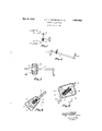
Figure 1 discloses diagrammatically one arrangement of our steering wheel invention;
Figure 2 is a fragmentary view of the mechanism of Figure l disclosing, in detail,
' the diagonally-extending transverse shaft and cooperating steering mechanism;
Figures 3 and 4 disclose details of a modified form of steering mechanism; and
Figure 5 discloses, in longitudinal section, a further modified form of steering mechanism.
Figures 1 and 2 show diagrammaticaliy a simple embodiment of our invention tnere being provided a transversely-extending shaft 1, which is inclined (Fig. 2) in order to bring, in the same horizontal plane, the extremities of levers 2 and 3, which control the front wheels by means of rods or drag links 4 and 5 (Fig. 1).
Figures 3 and 4 disclose a second embodiment of the invention in which transversely extending shafts 6 and 7, rotate inversely under the action of the steering wheel which is keyed on a shaft or steering post 8, and on which a screw 9 is provided in order to constrain a nut 10 to slide longitudinally; the nut 10 which cannot rotate, controls the angular displacements of levers 13 and 14 by means of the links 11 and 12.
According to a further embodiment disclosed in Figure 5, a screw 9 is provided on the steering post or shaft 8 operative to displace a nut 17, the latter controlling the angular displacement of levers 18 and 19, operatively connected to two segments 15 and 16, the latter in operative engagement with the longitudinally movable nut 17.
There is thus provided a very simple means for steering the dirigible wheels of an automotive vehicle, the transversely-extending shaft of the mechanism being inclined for the purposes heretofore indicated. The transverse shaft may also be conveniently disposed between the crank shaft and the clutch of the vehicle.
Other advantages of the structure will be obvious to those skilled in the art including the interchangeability of the steering arms 2 and 3 and the movement of the drag links in opposite directions in the same plane to effect the directional control of the vehicle.
Having thus described our invention, what we claim as new and desire to secure by Letters Patent is:
1. Steering mechanism for the swiveled front wheels of a motor vehicle comprising, in'combination, a steering post, a unitary shaft extending transversely of the vehicle and coupled with the post to be rotated thereby, such shaft arranged diagonally in a vertical plane and provided at opposite ends with oppositely directed arms and connections leading from said arms in substantially the same horizontal plane to the swiveled wheels.
2. Steering mechanism comprising, in combination with a steering post provided with a worm member, a unitary shaft extending transversely thereof and coupled with the worm for rotation, said shaft arranged diagonally in a vertical plane and provided at opposite ends with oppositely directed. arms having their extremities disposed in substantially the same horizontal plane, and a connection from the extremity of each arm to the adjacent swiveled wheel.
3. Steering mechanism comprising, in combination, a steering post, a unitary transversely extending shaft coupled therewith for rotation, said shaft arranged diagonally in a vertical plane and provided at opposite ends with oppositely directed arms having end connections disposed in substantially the same horizontal plane.
JOSEPH FREDERIC .IULIEN BETHENOD.
NEMORIN LAURENT CAUSAN.
Applications Claiming Priority (1)
| Application Number | Priority Date | Filing Date | Title |
|---|---|---|---|
| FR630501T | 1926-06-04 |
Publications (1)
| Publication Number | Publication Date |
|---|---|
| US1908008A true US1908008A (en) | 1933-05-09 |
Family
ID=8991139
Family Applications (1)
| Application Number | Title | Priority Date | Filing Date |
|---|---|---|---|
| US196291A Expired - Lifetime US1908008A (en) | 1926-06-04 | 1927-06-03 | Steering mechanism |
Country Status (2)
| Country | Link |
|---|---|
| US (1) | US1908008A (en) |
| FR (1) | FR630501A (en) |
Cited By (4)
| Publication number | Priority date | Publication date | Assignee | Title |
|---|---|---|---|---|
| US2731277A (en) * | 1955-06-20 | 1956-01-17 | Fred A Pearne | Differential steering mechanism |
| US2768834A (en) * | 1949-02-24 | 1956-10-30 | Wilson Roland | Vehicle construction kit |
| US3023629A (en) * | 1958-07-26 | 1962-03-06 | Zahnradfabrik Friedrichshafen | Booster steering mechanism for motor vehicles |
| US6272409B1 (en) | 1998-09-24 | 2001-08-07 | Dana Corporation | Motor vehicle steering box with Ackerman control |
Families Citing this family (1)
| Publication number | Priority date | Publication date | Assignee | Title |
|---|---|---|---|---|
| US2600885A (en) * | 1948-08-03 | 1952-06-17 | Kopfli Josef | Steering gear for motor vehicles |
-
1926
- 1926-06-04 FR FR630501D patent/FR630501A/en not_active Expired
-
1927
- 1927-06-03 US US196291A patent/US1908008A/en not_active Expired - Lifetime
Cited By (4)
| Publication number | Priority date | Publication date | Assignee | Title |
|---|---|---|---|---|
| US2768834A (en) * | 1949-02-24 | 1956-10-30 | Wilson Roland | Vehicle construction kit |
| US2731277A (en) * | 1955-06-20 | 1956-01-17 | Fred A Pearne | Differential steering mechanism |
| US3023629A (en) * | 1958-07-26 | 1962-03-06 | Zahnradfabrik Friedrichshafen | Booster steering mechanism for motor vehicles |
| US6272409B1 (en) | 1998-09-24 | 2001-08-07 | Dana Corporation | Motor vehicle steering box with Ackerman control |
Also Published As
| Publication number | Publication date |
|---|---|
| FR630501A (en) | 1927-12-05 |
Similar Documents
| Publication | Publication Date | Title |
|---|---|---|
| US2368135A (en) | Steering apparatus | |
| US1806136A (en) | Steering device | |
| US2427340A (en) | Steering mechanism | |
| US1908008A (en) | Steering mechanism | |
| US2707109A (en) | Dual control steering connection for motor vehicles | |
| US2447815A (en) | Fluid pressure controlled power steering mechanism | |
| US1473369A (en) | Parking device for automobiles | |
| US2367151A (en) | Four wheel drive assembly for trucks | |
| US1877332A (en) | Motor vehicle | |
| US1577559A (en) | Motor vehicle | |
| US2485792A (en) | Gear and rack type control | |
| US1723789A (en) | Hydraulic steering mechanism | |
| US1289296A (en) | Four-wheel truck steering mechanism. | |
| US1340024A (en) | And william g | |
| US788852A (en) | Motor-vehicle. | |
| US1512424A (en) | Vehicle steering gear | |
| US2644341A (en) | Steering mechanism for motor vehicles and the like | |
| US1319367A (en) | George a | |
| US1760733A (en) | Steering gear | |
| US1526905A (en) | Steering-gear control | |
| US2337002A (en) | Steering mechanism | |
| US1444563A (en) | Steering gear | |
| DE1007037B (en) | Car slewing crane | |
| US944645A (en) | Wheeled vehicle. | |
| US1399624A (en) | Motor-sleigh |