US1907784A - Dump vehicle - Google Patents
Dump vehicle Download PDFInfo
- Publication number
- US1907784A US1907784A US480037A US48003730A US1907784A US 1907784 A US1907784 A US 1907784A US 480037 A US480037 A US 480037A US 48003730 A US48003730 A US 48003730A US 1907784 A US1907784 A US 1907784A
- Authority
- US
- United States
- Prior art keywords
- vehicle
- hinge
- dumping
- casting
- hinges
- Prior art date
- Legal status (The legal status is an assumption and is not a legal conclusion. Google has not performed a legal analysis and makes no representation as to the accuracy of the status listed.)
- Expired - Lifetime
Links
Images


Classifications
-
- B—PERFORMING OPERATIONS; TRANSPORTING
- B60—VEHICLES IN GENERAL
- B60P—VEHICLES ADAPTED FOR LOAD TRANSPORTATION OR TO TRANSPORT, TO CARRY, OR TO COMPRISE SPECIAL LOADS OR OBJECTS
- B60P1/00—Vehicles predominantly for transporting loads and modified to facilitate loading, consolidating the load, or unloading
- B60P1/04—Vehicles predominantly for transporting loads and modified to facilitate loading, consolidating the load, or unloading with a tipping movement of load-transporting element
- B60P1/28—Tipping body constructions
- B60P1/283—Elements of tipping devices
Definitions
- My invention relates to dumping vehicles and, in particular, to a vehicle Awhich is adapt-- ed to dump on either sideandto the rear.
- the invention comprises a novel method and means for effecting' ⁇ a tilting movement of a dumping body.
- three-way dumping is effected by supporting the dumping body at four points, for example, adjacentthe corners. Arrangements are made for receiving the corner supports, whichgenerally take the form ofhingepins, into associated cups or sockets.' By locking anyv two adjacent pins to their sockets,pit is possible to tilt the body about an axis passing through said pins, the remaining .pins being free to rise from their sockets as the body is tilted.
- the hinge pins now in use include knuckles ⁇ and lpivot pins,
- This type of hinge has proved to have certain objectionable features, one of which is that after ya certain amount of wear, the body, when tilted, tends to swing oif of the pins toward the V2,5 low side. 2 This Aresults in the failure of the pins on the highV side to reenter their cups or sockets. If the body islowered without properly seating the hinge pins, it is obvious that on dumping toward the other side, the
- the lower hinge member has the form of a hook or toroidal bearing extending from the vehicle chassis.
- the lupper hinge member is a casting secured to the dumping b ody and has a downwardly projecting yokeor ring portion resting on and extending around the hook 4or toroidal bearing".
- the 'two lmem- .45 bers have bearing surfacescorrespondingly COMPANY, OF YOUNGSTOWN, OHIO, A CORPORATION i shaped substantiallytoroidalrso as to l l' mit the upper hinge member to rotate upon the lower in two planes normalto each other.
- the invention eliminates'all lostmotion between the body andits supports,sincfe the upper hinge Vmember is rigidly secured to the body. There is no difficulty experienced in maintaining thehinge ⁇ members in proper alinement, as the body isgbeing lowered. It will thusbe practically impossible to throw the body off the chassis, because of failure of the ⁇ hinge members to cooperate properly as' the body is lowered.
- the invention also reduces the cost yof manufacture since all mae chine work is eliminated andv ⁇ only the. two one-piece castings are necessary tol constitute the hinge. Y
- I also make provision whereby the weight i of the body is taken off thebearing.l members as the body is lowered. A, strong support is thus afforded for the body 'and the bea-ring surfaces are relieved of the weight ofthe body, which would cause excess wear thereof.
- Another advantage of the, invention isthatit makes it possible to space the hinges further apart than is possible with the present type. As a result, vit is possible to employ a'longer stroke of the hoist mechanism Vand to move the latter nearer to the front of the body toward the ideal position, namely',fthe"cen ter of the body.
- a vehicle such as a motor truck, having a chassis illustrated in part at 10.
- a chassis illustrated in part at 10.
- I mount front and rear cross members,
- the casting 12 also has a cap 16 shaped to conform to the upper surface of the cross member 11 and'resting thereon.
- a downwardly projecting upper hinge member 17 which has a yoke or ring portion 18 of toroidal shape, resting on and extending partly around the hook 13 of the lower member 12.
- the castings 12 and 17 are ribbed and flanged for additional strength and rigidity.
- the upper hinge member 17 directly supports the vehicle body which hasside Z-bars 19 at its bottom which are riveted to the hinge member 17 by the rivets 20.
- the casting 17 4J) is provided with an opening 21 for a purpose to be described later.
- the casting 17 has a flat surface 22 adjacent the upper end thereof for cooperation with the shoulder 15 on the lower casting 12.
- this member has a sleevev 23 for receiving a locking bar 24.
- the bar 24 is adapted to pass through the opening 21 in the upper casting 17 and through a corresponding opening 25 near the end of the'hoo-k portion 13 of the casting 12.
- a sleeve 2.6 is riveted tol the rod 24 for entering the openings 21 and ⁇ 25.
- ASuitable oper- Y- ating means (not shown) is provided for the locking bar 24, preferably of the type described in my copending application, Serial No. 257,707, filed February 28, v71928,. for hoistmechanism. T y
- the hinges at both'ends of the rear cross member 11 are locked by the bar 24, which is of such length that it overlies the yokes 18 of the castings 17 at opposite sides of the body.
- the bar 24 is of such length that it overlies the yokes 18 of the castings 17 at opposite sides of the body.
- the body When the body is raised by any suitable hoist mechanism, the corresponding hinges at the front of the vehicle being free to rise, the body will be tilted about an axis passing through the center of the toroidal portion 13 of the casting 12.
- the yoles 18 of the front hinges which are identical with the rear hinges, rise from their toroidal bearings as the body is tilted.
- the opening 21 in the casting 17 permits the latter to rotate, although the locking bar passes therethrough.
- the body' may be lowered in the same manner, whereupon the yokes of the front hinges reengage their toroidal bearings and the body is supported by the engagement of the surfaces 15 and 22.
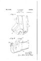
- the tilted position of the member 17 is shown in chain lines in Figure 1. y
- the weight of the body is transmitted directly to the vehicle frame at all iio times, except when dumping, in whichv case tively low cost and the fact that they require no machining, ⁇ eliminates an additional item of expense encountered in the manufacture of present tylpes of hinges.
- a hinge for a tilting vehicle body including a frame and a transverse supporting member thereon, comprising a castlng secured to said transverse member, having an outwardly projecting, upstanding, open-top, j
- hook portion thereon, and a casting secured to said body having an open-bottom yoke portion projecting downwardly and outwardly, resting on and partially encircling said hook portion, and adapted to be supported in'said hook portion for rotation in the plane of said transverse member and in a plane perpendicular thereto.
- a hinge for a tilting vehicle body supported on a frame comprising a member on said frame having an outwardly projecting, upstanding, open-top, hook portion thereon, and a member on said body having an openbottom, yoke portion projecting downwardly and outwardly of the body, resting on and partially encircling said hook portion and adapted to be supported in said hook portion for rotation thereon in two perpendicular planes.
Landscapes
- Engineering & Computer Science (AREA)
- Transportation (AREA)
- Mechanical Engineering (AREA)
- Body Structure For Vehicles (AREA)
Description
C. P. GALANOT May 9, 1933.
DUMP VEHICLE Filed Sept. 6, 1930 3 vSheets-Shea?. l
May 9, 1933.
C. P. GALANQT DUMP VEHICLE Filed Sept. 6, 1950 3 Sheets-Sheet 2 mvENToR May 9, 1933.
C P. GALANOT DUMP VEHICLE 3 Sheets-Sheet 3 Filed Sept. 6, 1930 INVENT'OR Patented May 9, 1933 A.UNITED STATES PA'IENTl oFFlcEf 1 CAMILLE P. GALANOT, or YotfNGsrowN, OHIO, Assreivon 'ro THE 'COMMERCIAL SHEARING AND STAI/[PING OF OHIO DUMP VEHICLE Application mea september s, 1930. serial-Ne. 480,037.
My invention relates to dumping vehicles and, in particular, to a vehicle Awhich is adapt-- ed to dump on either sideandto the rear. Specifically, the invention comprises a novel method and means for effecting'` a tilting movement of a dumping body.
According to present practices in the dumping vehicle art, three-way dumping is effected by supporting the dumping body at four points, for example, adjacentthe corners. Arrangements are made for receiving the corner supports, whichgenerally take the form ofhingepins, into associated cups or sockets.' By locking anyv two adjacent pins to their sockets,pit is possible to tilt the body about an axis passing through said pins, the remaining .pins being free to rise from their sockets as the body is tilted. Y The hinge pins now in use include knuckles` and lpivot pins,
both of which must be machined. This type of hinge has proved to have certain objectionable features, one of which is that after ya certain amount of wear, the body, when tilted, tends to swing oif of the pins toward the V2,5 low side. 2 This Aresults in the failure of the pins on the highV side to reenter their cups or sockets. If the body islowered without properly seating the hinge pins, it is obvious that on dumping toward the other side, the
V30 bodywill be thrown off the vehicle chassis.
f one tothe vehicle frame, so as to constitute a rigid hinge which permits dumping the body toward Vthe side or tov therear. The lower hinge member has the form of a hook or toroidal bearing extending from the vehicle chassis.l The lupper hinge member is a casting secured to the dumping b ody and has a downwardly projecting yokeor ring portion resting on and extending around the hook 4or toroidal bearing".` The 'two lmem- .45 bers have bearing surfacescorrespondingly COMPANY, OF YOUNGSTOWN, OHIO, A CORPORATION i shaped substantiallytoroidalrso as to l l' mit the upper hinge member to rotate upon the lower in two planes normalto each other.
The invention eliminates'all lostmotion between the body andits supports,sincfe the upper hinge Vmember is rigidly secured to the body. There is no difficulty experienced in maintaining thehinge `members in proper alinement, as the body isgbeing lowered. It will thusbe practically impossible to throw the body off the chassis, because of failure of the `hinge members to cooperate properly as' the body is lowered. The invention also reduces the cost yof manufacture since all mae chine work is eliminated andv` only the. two one-piece castings are necessary tol constitute the hinge. Y
I also make provision whereby the weight i of the body is taken off thebearing.l members as the body is lowered. A, strong support is thus afforded for the body 'and the bea-ring surfaces are relieved of the weight ofthe body, which would cause excess wear thereof. Another advantage of the, invention isthatit makes it possible to space the hinges further apart than is possible with the present type. As a result, vit is possible to employ a'longer stroke of the hoist mechanism Vand to move the latter nearer to the front of the body toward the ideal position, namely',fthe"cen ter of the body. s, 1 't For a complete understanding of theinvention, reference 'should bey made to the accompanying drawings'llustrating a present preferred ,embodiment thereof. The drawings are intended merely as illustrations of one of the hinge-,flocking thereon from oneside ofthe truclito which it is applied,
invention is adapted for use in connection with a vehicle such as a motor truck, having a chassis illustrated in part at 10. Upon the chassis, I mount front and rear cross members,
Vof which the rear cross member is shown at 11. To each end of the cross members, I secure a lower hinge member-12 having a bearing or hook portion 13 by means of rivets 14. The bearing surface of the hook portion is in the form of lan anchor ring or toroid and is rounded in two directions. A shoulder 15 1 is formed integral with the casting 12, for a purpose which will be described hereinafter.
The casting 12 also has a cap 16 shaped to conform to the upper surface of the cross member 11 and'resting thereon.
Cooperating with the lower hinge member 12 is a downwardly projecting upper hinge member 17 which has a yoke or ring portion 18 of toroidal shape, resting on and extending partly around the hook 13 of the lower member 12. The castings 12 and 17 are ribbed and flanged for additional strength and rigidity. The upper hinge member 17 directly supports the vehicle body which hasside Z-bars 19 at its bottom which are riveted to the hinge member 17 by the rivets 20. The casting 17 4J) is provided with an opening 21 for a purpose to be described later.
The casting 17 has a flat surface 22 adjacent the upper end thereof for cooperation with the shoulder 15 on the lower casting 12. Thus, when the body carried on the Z-bars 19 is fully lowered, as shown in Figure 2, the weight of the bodyis transmitted from the surface 22 to the shoulder 15 and thence to the cross member 11 and the vehicle chassis.
Referring again to the lower casting 12, and particularly to Figure 3, this member has a sleevev 23 for receiving a locking bar 24. The bar 24 is adapted to pass through the opening 21 in the upper casting 17 and through a corresponding opening 25 near the end of the'hoo-k portion 13 of the casting 12. A sleeve 2.6 is riveted tol the rod 24 for entering the openings 21 and`25. ASuitable oper- Y- ating means (not shown) is provided for the locking bar 24, preferably of the type described in my copending application, Serial No. 257,707, filed February 28, v71928,. for hoistmechanism. T y
When it is desired to dump the truck body toward the rear, the hinges at both'ends of the rear cross member 11 are locked by the bar 24, which is of such length that it overlies the yokes 18 of the castings 17 at opposite sides of the body. When the body is raised by any suitable hoist mechanism, the corresponding hinges at the front of the vehicle being free to rise, the body will be tilted about an axis passing through the center of the toroidal portion 13 of the casting 12. The yoles 18 of the front hinges, which are identical with the rear hinges, rise from their toroidal bearings as the body is tilted. The opening 21 in the casting 17 permits the latter to rotate, although the locking bar passes therethrough. The body' may be lowered in the same manner, whereupon the yokes of the front hinges reengage their toroidal bearings and the body is supported by the engagement of the surfaces 15 and 22. The tilted position of the member 17 is shown in chain lines in Figure 1. y
When it is desired to dump the truck 'toward they side, the locking bar 24 and its counterpart in the front cross member are shifted toward the side to which the body I is to be. dumped. The hinges on that side ofthe body are thus locked while those on the opposite side are freed. Application of hoisting force nowcauses the body to tilt about an axis passing through the 4center of the yoke portion 18, as shown in Figure 3. The yoke portions on the opposite side of the body rise from their toroidal bearings, as previously described in the rear dumping operation. When the dumping has been completed and the body is again lowered, the yoke portions 18 enter their toroidal bearings and the weight of th-e body is again evenly distributed on the ends of the cross members. The side dumping position of the member 17 is shown in chain lines in Figure 2',
It will be obvious from the foregoing'description that the invention providesa strong and rigid hinge consisting of but two parts,
which are so designed as to permit rotation lof the upper hinge member in the lower member in two planes which are at right angles. Since the body is at all'times supported on at least two of the castings 17, there willbe no side slippage` of the body when tilted. As the body is lowered, each of the yokes 18 on the high side will be guided directly into, their toroidal bearings. Accidental throwing 0H of the body, due to a failure ofthe hinges ...11.20
to engage properly, is thus avoided and safety ofoperation of the vehicle is much increased. In addition, the weight of the body is transmitted directly to the vehicle frame at all iio times, except when dumping, in whichv case tively low cost and the fact that they require no machining,`eliminates an additional item of expense encountered in the manufacture of present tylpes of hinges.
Although have described and illustrated but a single present preferred embodiment of the invention, I do not intend to be limited to the specific details of the structure shown, since the invention may be embodied in other forms and any changes in the embodiment illustrated may be made within the spirit of the invention land are not to be considered as departures from the scope of the appended claims.
I claim:
1. A hinge for a tilting vehicle body including a frame and a transverse supporting member thereon, comprising a castlng secured to said transverse member, having an outwardly projecting, upstanding, open-top, j
hook portion thereon, and a casting secured to said body having an open-bottom yoke portion projecting downwardly and outwardly, resting on and partially encircling said hook portion, and adapted to be supported in'said hook portion for rotation in the plane of said transverse member and in a plane perpendicular thereto.
2.- A hinge for a tilting vehicle body supported on a frame, comprising a member on said frame having an outwardly projecting, upstanding, open-top, hook portion thereon, and a member on said body having an openbottom, yoke portion projecting downwardly and outwardly of the body, resting on and partially encircling said hook portion and adapted to be supported in said hook portion for rotation thereon in two perpendicular planes.
In testimony whereof I have hereunto set my hand.
CAMILLE P. GALANOT.
Priority Applications (1)
| Application Number | Priority Date | Filing Date | Title |
|---|---|---|---|
| US480037A US1907784A (en) | 1930-09-06 | 1930-09-06 | Dump vehicle |
Applications Claiming Priority (1)
| Application Number | Priority Date | Filing Date | Title |
|---|---|---|---|
| US480037A US1907784A (en) | 1930-09-06 | 1930-09-06 | Dump vehicle |
Publications (1)
| Publication Number | Publication Date |
|---|---|
| US1907784A true US1907784A (en) | 1933-05-09 |
Family
ID=23906421
Family Applications (1)
| Application Number | Title | Priority Date | Filing Date |
|---|---|---|---|
| US480037A Expired - Lifetime US1907784A (en) | 1930-09-06 | 1930-09-06 | Dump vehicle |
Country Status (1)
| Country | Link |
|---|---|
| US (1) | US1907784A (en) |
-
1930
- 1930-09-06 US US480037A patent/US1907784A/en not_active Expired - Lifetime
Similar Documents
| Publication | Publication Date | Title |
|---|---|---|
| US2036344A (en) | Freight car for transporting vehicles | |
| US3963259A (en) | Sliding axle assembly for flat deck trailers and the like | |
| US3197235A (en) | Removable self-stabilizing landing gear for semi-trailers | |
| US2672243A (en) | Jack with adjustable load-receiving table | |
| US1907784A (en) | Dump vehicle | |
| US3528683A (en) | Tractor-trailer fifth wheel coupling | |
| US2462868A (en) | Automotive truck bed | |
| US2859889A (en) | Easy loading shifting axle trailer | |
| US2316374A (en) | Vehicle supporting truck | |
| US2252135A (en) | Wheel vehicle train, unit, and connection | |
| US1909969A (en) | Dump wagon | |
| US3582104A (en) | Pivotal axle mounting for an aircraft transfer vehicle | |
| US1743436A (en) | Trailer-frame structure | |
| US3208615A (en) | Flat bed trailer | |
| US1479828A (en) | Semitrailer | |
| US3135528A (en) | Folding king pin | |
| US2677552A (en) | Stake apparatus for vehicles | |
| US1812915A (en) | Dump truck | |
| US2135820A (en) | Vehicle | |
| US2963989A (en) | Trailer support arrangement | |
| US2090819A (en) | Towing equipment | |
| US2091406A (en) | Running gear assembly | |
| US1423238A (en) | Leading truck for railway motor cars | |
| USRE22102E (en) | Heavy duty vehicle | |
| US2284140A (en) | Tiltable body equipped land vehicle |