US1907600A - Machine for making friction elements - Google Patents
Machine for making friction elements Download PDFInfo
- Publication number
- US1907600A US1907600A US402100A US40210029A US1907600A US 1907600 A US1907600 A US 1907600A US 402100 A US402100 A US 402100A US 40210029 A US40210029 A US 40210029A US 1907600 A US1907600 A US 1907600A
- Authority
- US
- United States
- Prior art keywords
- hopper
- machine
- roll
- belt
- strip
- Prior art date
- Legal status (The legal status is an assumption and is not a legal conclusion. Google has not performed a legal analysis and makes no representation as to the accuracy of the status listed.)
- Expired - Lifetime
Links
- 239000000463 material Substances 0.000 description 42
- 239000000203 mixture Substances 0.000 description 13
- 238000000465 moulding Methods 0.000 description 7
- 238000010276 construction Methods 0.000 description 6
- 239000002131 composite material Substances 0.000 description 4
- 239000002783 friction material Substances 0.000 description 2
- 230000002093 peripheral effect Effects 0.000 description 2
- 230000000284 resting effect Effects 0.000 description 2
- 238000005096 rolling process Methods 0.000 description 2
- NRTLIYOWLVMQBO-UHFFFAOYSA-N 5-chloro-1,3-dimethyl-N-(1,1,3-trimethyl-1,3-dihydro-2-benzofuran-4-yl)pyrazole-4-carboxamide Chemical compound C=12C(C)OC(C)(C)C2=CC=CC=1NC(=O)C=1C(C)=NN(C)C=1Cl NRTLIYOWLVMQBO-UHFFFAOYSA-N 0.000 description 1
- 239000004744 fabric Substances 0.000 description 1
- VKYKSIONXSXAKP-UHFFFAOYSA-N hexamethylenetetramine Chemical compound C1N(C2)CN3CN1CN2C3 VKYKSIONXSXAKP-UHFFFAOYSA-N 0.000 description 1
- 238000004519 manufacturing process Methods 0.000 description 1
- 239000002184 metal Substances 0.000 description 1
- 239000002759 woven fabric Substances 0.000 description 1
Images


Classifications
-
- B—PERFORMING OPERATIONS; TRANSPORTING
- B29—WORKING OF PLASTICS; WORKING OF SUBSTANCES IN A PLASTIC STATE IN GENERAL
- B29C—SHAPING OR JOINING OF PLASTICS; SHAPING OF MATERIAL IN A PLASTIC STATE, NOT OTHERWISE PROVIDED FOR; AFTER-TREATMENT OF THE SHAPED PRODUCTS, e.g. REPAIRING
- B29C43/00—Compression moulding, i.e. applying external pressure to flow the moulding material; Apparatus therefor
- B29C43/22—Compression moulding, i.e. applying external pressure to flow the moulding material; Apparatus therefor of articles of indefinite length
Definitions
- Another object of the invention is to apply a Vflexible backing to the composition strip as it is molded in the rollingoperation.
- Av further object of the invention is to provide means for automatically feeding th-e composition material from the hopper to the bight of the molding rolls in substantially uniforn. quantity for making a strip of the desired cross section.
- Fig. 2 is ai detail sectional'view onthe line 2 2 of Fig. 1'.
- Fig.'3 is airear end elevation of the machine.
- Fig. 4 is a ⁇ detail enlarged view showing the throat of the hopper and the gate for controlling the flow of material therethrough.
- Fig; 5 is a detail transverse sectional view on the line 5 5 of Fig. 1. ⁇
- Fig. 6 is a detail sectional view on the line 6&6 of Fig. l.
- Fig. 7 partly broken away and in section, illustrates an embodiment of the invention having a cleated feed-er belt or carrier.
- Fig. 8 is a detail enlarged view of a portion of the cleated feeder belt.
- Fig. 9 is a detail enlarged view showing the throat of the hopper and the gate as used *Y in thev construction ofvFig. 7 j
- Fig. 10 is a sectional view on ythe' line l0-10 of Fig. 7.- j
- the machine comprises a frame 5 .of suitable construction and .including a body 6.
- a power motor .7 is mounted on .the base and through the chain 8 drives the main power shaft 9.
- a gear 10 on shaft 9 drives a gear 11 on shaft 12 and the latter gear drives idle gears 13 VonY shaft 14 and 15 on shaft 16.
- the latter gear drives gear 17 on shaft 18.
- the shaft 12 carries a lower forming roll 19 in fixed position. This forming roll has a flange 2O at one endand a collar 21 is movably mounted on the roll to vary the width of the liner strip 22 being formed.
- the shaft 18 carries an upper forming roll 23 which lits between the flange 20 and the collar 21 on the roll 19 and is adapted to be adjusted vertically to vary the thickness of the liner strip 22 beingformed. This adjustment is effected by mounting the upper forming roll shaft 18 in eccentric bearings 24 Y in theframe, these bearings being capable of adjustment by operating the hand screw adj ustment device 25.
- shaft 16 is carried by angle arms 16 whichare secured in adjusted position at 16" on the frame.
- An-endless feeder belt26 travels-'on the lower forming roll 19 between the flange 2O and the collar 21 and over the ⁇ roll 27 mounted on a shaft 28.
- a belt tightener roll29 is mounted on a counter-weighted lever 29 or its equivalent which is pivotally mounted on the frame and supports the roll in contact with the feeder belt to hold it taut.
- the material is carried on by the feeder belt from the;V
- a reel 34 is mounted on the frame to carry a roll of backing material 35 which is fed between the rolls with the material and is embedded in the material on one face thereof as indicated in Fig. 2.
- Different kinds of backing material may be used but I have found it convenient and satisfactory to provide woven wire mesh of relatively light gauge and small openings.
- the machine may be easily adjusted for making a strip of a different width by providing a supply of backing material of the proper width and an upper roll of the proper width and by adjusting the collar 2l with reference to the backing and the upper roll to form a mold cavity between the upper roll, the feeder belt, the flange 20 andy the collar 21.
- a feeder belt should be used of approximately the width of the mold cavity, as indicated in Fig.
- the gate device 32 is provided with means for laterally adjusting it to approximately the width of the feeder belt, Fig. 4. While I prefer that the backing material shall be of the same width as the friction element to be produced and that the feeder belt shall be of the same width this'is not absolutely necessary and there may be variations in width within reasonable limits and still produce a satisfactory product.
- a stripper 36 On a bracket 36 on the machine I mount a stripper 36, Fig.
- This wiper smooths down any fins that may bepresentat the edges of the product and may also serveV to wipe ofiI any material that Y may be lodged on the top of the product as it leaves the mold machine.
- the wiper 1s preferablyl made of metal and of sufficient weight to co-operate with the stripper to confine the product after it leaves the rolls and to prevent any tendency of the composition Vto swell after rolling, thereby assisting to size the product as to thickness and insure fairly accurato and uniform thickness.
- 6()v Y I also preferably provide Scrapers 38 for the upper roll, 39 for the lower roll,and 40 for the feeder belt to remove any of the composition material which may be carried thereby beyond
- the shaft 28 carrying roll 27 is mounted on the bracket 42 so that it will be adjusted with the hopper.
- the angle strip 45 is fastened onV the inner side of the hopper and an angle plate 46'is fastened to the angle strip and is adjustably fastened to the frame, Fig. l. This provides for adjustably supportingthe hopper at its rear end and at its front end in any desired tilted position within the limits of adjustment for controlling the flow of composition material from the hopper through the bight into the molding cavity. l'
- My invention provides a machine of simple and compact construction for making liner strips rapidly and uniformly in predetermined width and thickness.
- the strip is formed or molded ina rolling operation and at the same time the backing is embedded therein.
- This backing may be of any suitable reticulated material or fabric inc-luding wire mesh and woven fabric.
- the upper forming roll is preferably knurled for feeding the backing from the reel through molding position.
- a relatively stiff flexible backing may be used but generally speaking the backing will be of such character that the strip liner issuing from the machine will be limber.
- the strip liner may be carried away from the machine in a straight length and preserved in long lengths for future 0perations or it may be cut into liner lengths and mounted on forms for the curing operation.v After the machine is started in op- ⁇ eration it requiresk only that the product be properly taken away from the machine and the hopper be refilled when required to carry on the operation indefinitely and provision may be made for delivering the liner'strip directly from this molding machine into the curing oven.
- This invention provides highly efficient means for producing the liner strips ata relatively low manufacturing cost.
- Fig. 7 I have shown a feeder or carrier belt 47 having thereon a plurality of spaced cleats 48 which drag the material forward from the bottom of the hopper and deposit it between the throat 32 of the hopper 30, the upper forming roll 18 and the lower forming roll 19.
- the belt does not travel around the lower forming roll buttravels on a small rolll 49 supported in thefframe below the lower front end of the hopper.
- the gate device 5() and the opposite sidev 51 of the forming rolls as heretofore described by the movement thereof. It will be noted that the center of the upper forming roll is offset forwardly o f the center of the lower forming roll so that the material carried forward by the feeder belt is supported on the lower formin roll and is carried forward thereby.
- the belt tightener roll 29 is supported to engage the inside of the belt and the roll 27 drives the belt.
- a sprocket chain 19 is driven by a sprocket wheel 19 on the shaft 12 and, in turn, drives a sprocket wheel 28 on the shaft 28, Fig. l0.
- a clutch member 28 is fastened to the sprocket 28 and both float on the shaft 28. The other member 28 of the clutch is keyed to the shaft 28 and is normally pressed in operative engagement with the member 28 by spring 52.
- the embodiment in Figs. 7, l0 is the same or substantially the same as that heretofore described and therefore I have not considered it necessary to show more detail of the machine in Fig. 7.
- the material may pile up in the bight of the forming rolls faster than it will be taken away, in which case the feeding movement ofthe belt will be retarded and the clutch will slip until the pressure is relieved and then the clutch will take hold again and the belt will resume its feeding action.
- a material receiving hopper lower and upper forming rolls, an endless belt traveling through the hopper on the bottom thereof and around guiding pulleys therefor disposed on one side of said lower Vand upper forming rolls, means for driving the lower forming roll, and means for driving the belt from the lower forming roll.
- a material receiving hopper lower and upper forming rolls, an endless belt traveling through the hopper on t-he bottom thereof and around guiding pulleys therefor dis-v posed at one side of said forming rolls, means for driving the lower forming roll, means for driving the belt from the lower forming roll, and means for guiding material from the hopper and on the belt to the forming rolls.
- composition friction elements In a machine for making composition friction elements, the combination of a material receiving hopper, a pair of forming the collar to compress material passing between the rolls.
- a material receiving hopper having slots at its front and back adjacent its bottom, an endless belt traveling through said slots and on the bottom of the hopper and having cleats thereon to insure movement of a substantially uniform quantity of material from the hopper, 1 5
- G In a machine for making lcomposition friction elements, the combination of a material receiving hopper, said hopperh'aving slots at its front and back adjacent its bot tom, a pair of forming rolls mounted in front of the hopper, an endless belt traveling through said slots and on the'bottom of the hopper to carry material from the hopper, and having cleats thereon to a guiding throat leading to the rolls, and guiding rollers disposed on one side of said guiding throat and having said belt directed therearound whereby'said belt continually passes material to said throat during operation thereof.
- a pair of'rolls for forming material delivered from the hopper into a strip
- means for delivering material from the hopper to the forming rolls a support for the strip after it leaves the rolls, and a weighted floating wiper resting upon the strip on said support and extending over the strip and past the edges thereof to smooth said strip to remove tins and the like therefrom as said strip moves over said support.
- a machine for making composition friction material in a continuous strip the combination of a material receiving hopper, a pair of rolls for forming material delivered from the hopper into a strip, means for delivering material from the hopper to the forming rolls, a bracket on the machine, a stripper mounted on the bracket and arranged to insure stripping of the strip from the lower roll, said stripper also forming a supportvfor the strip after it leaves the rolls, and a weighted iioating wiper resting upon the strip on the support and abutting said bracket, said wiper extending across said strip and past the edges thereof to smooth said strip and to remove fins and the like therefrom as said strip moves over said support.
- a material receiving hopper In a machine for making composition friction elements, the combination of a material receiving hopper, an endless belt traveling through the hopper on the bottom thereof, lower and upper forming rolls, guiding pulleys for the endless belt and disposed on one side of said forming rolls, means for driving the lower forming roll, means for driving the belt from the lower forming roll, a reel containing a supply of backing material which is directed therefromaround upper forming roll to pass between the rolls whereby material fed from the hopper to said forming rolls is forced into lsaid backing material during passage between said forming rolls.
- afmachine for making composition Vfriction elements the combination of a material receiving hopper, an endless belt travcling through the hopper on the bottom thereof, cleats on said beltV for moving material from said hopper, a lower forming roll, an upper forming roll cooperating with the lowerforming roll and offset from vertical alignnient with said lower roll, guiding pulleys for said endless belt and disposed on one side ofA said forming rolls, a guiding throat extending between the discharge end Harter N. SMITH.
Landscapes
- Engineering & Computer Science (AREA)
- Mechanical Engineering (AREA)
- Dry Formation Of Fiberboard And The Like (AREA)
Description
May 9, 1933. H. N SMlTH 1,907,600
MACHINE FOR MAKING FRICTION ELEMENTS Filed Oct. 24, 1929 3 Sheets-Sheet l May 9, 1933. H. N. SMITH 1,907,600
MACHINE FOR MAKING FRICTION ELEMENTS Filed Oct. 24, 1929 3 Sheets-Sheet 2 May 9, 1933. H. N. SMITH 1,907,600
MACHINE FOR MAKING FRICTION ELEMENTS Filed'Oot. 24, 1929 3 Sheets-Sheet 5 Patented May 9, 1933 PATENT .oFFicE HARRY-'N'. I:SMIT-ii; or DETROIT, MIoHfGAN, AssIGNoR "To AMERICAN BRAKEBLOK' coRPoaATIoN, F NEW Yomgity., A CORPORATION oF NEW YORK MACHINE'VFOR MAKING rnIoTIoN ELEMENTS Appiicatio'n. mea october 24, 192e. serial No.' 402,100.
Another object of the invention is to apply a Vflexible backing to the composition strip as it is molded in the rollingoperation.
Av further object of the invention is to provide means for automatically feeding th-e composition material from the hopper to the bight of the molding rolls in substantially uniforn. quantity for making a strip of the desired cross section.
And further objects of the invention are to provide a machine of simple construction and compact arrangement which operates automatically to feed and mold the compositionmaterial; which can be readily adjusted to mold strips of different cross section, and which is otherwise conveniently constructed and `adapted for performing the required operations.
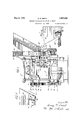
'I have illustrated the'invention in a selected` embodiment in the accompanying drawings in which Y v Y Fig. 11 is a right side elevation of themachine, partly broken' away and in section.
Fig. 2 is ai detail sectional'view onthe line 2 2 of Fig. 1'.
Fig.'3 is airear end elevation of the machine.
Fig. 4 is a` detail enlarged view showing the throat of the hopper and the gate for controlling the flow of material therethrough.
. Fig; 5 is a detail transverse sectional view on the line 5 5 of Fig. 1.`
Fig. 6 is a detail sectional view on the line 6&6 of Fig. l.
Fig. 7, partly broken away and in section, illustrates an embodiment of the invention having a cleated feed-er belt or carrier.
Fig. 8 is a detail enlarged view of a portion of the cleated feeder belt. Fig. 9 is a detail enlarged view showing the throat of the hopper and the gate as used *Y in thev construction ofvFig. 7 j
Fig. 10 is a sectional view on ythe' line l0-10 of Fig. 7.- j
Referring to the drawings the machine comprises a frame 5 .of suitable construction and .including a body 6.' A power motor .7 is mounted on .the base and through the chain 8 drives the main power shaft 9. A gear 10 on shaft 9 drives a gear 11 on shaft 12 and the latter gear drives idle gears 13 VonY shaft 14 and 15 on shaft 16. The latter gear drives gear 17 on shaft 18. The shaft 12 carries a lower forming roll 19 in fixed position. This forming roll has a flange 2O at one endand a collar 21 is movably mounted on the roll to vary the width of the liner strip 22 being formed. The shaft 18 carries an upper forming roll 23 which lits between the flange 20 and the collar 21 on the roll 19 and is adapted to be adjusted vertically to vary the thickness of the liner strip 22 beingformed. This adjustment is effected by mounting the upper forming roll shaft 18 in eccentric bearings 24 Y in theframe, these bearings being capable of adjustment by operating the hand screw adj ustment device 25. When the upper roll 23 is adjusted it will be desirable to adjust idle gear relative to gears 18 and 17 and for this purpose shaft 16 is carried by angle arms 16 whichare secured in adjusted position at 16" on the frame. An-endless feeder belt26 travels-'on the lower forming roll 19 between the flange 2O and the collar 21 and over the `roll 27 mounted on a shaft 28. A belt tightener roll29 is mounted on a counter-weighted lever 29 or its equivalent which is pivotally mounted on the frame and supports the roll in contact with the feeder belt to hold it taut.
This feeder beltenters the rear end of the composition hopper 30 through a slot 31 at the bottom of the hopper and travels along on the. bottom ofthe hopper to a throat 32 at the front end of the hopper. The material is carried on by the feeder belt from the;V
by the feeder belt from the hopper to the rolls. A reel 34 is mounted on the frame to carry a roll of backing material 35 which is fed between the rolls with the material and is embedded in the material on one face thereof as indicated in Fig. 2. Different kinds of backing material may be used but I have found it convenient and satisfactory to provide woven wire mesh of relatively light gauge and small openings. The machine may be easily adjusted for making a strip of a different width by providing a supply of backing material of the proper width and an upper roll of the proper width and by adjusting the collar 2l with reference to the backing and the upper roll to form a mold cavity between the upper roll, the feeder belt, the flange 20 andy the collar 21. A feeder belt should be used of approximately the width of the mold cavity, as indicated in Fig. 2, and provision is made for bodily moving the feeder belt sideways through a slot 30 at the bottom of theouter side of the hopper, Fig. 5. This slot is normally closed by a removable angle strip 30". The gate device 32 is provided with means for laterally adjusting it to approximately the width of the feeder belt, Fig. 4. While I prefer that the backing material shall be of the same width as the friction element to be produced and that the feeder belt shall be of the same width this'is not absolutely necessary and there may be variations in width within reasonable limits and still produce a satisfactory product. On a bracket 36 on the machine I mount a stripper 36, Fig. 1, with an edge directed between 'the molded part and the top portion of the lower roll to insure j stripping the product from the feeder belt on the lower roll This stripper is preferably projected for some disj tance away from the rolls to support the mamolding position. material through the throat can be very material as it comes from the rolls for delivery to a table or other support, or to a cutting machine as shown in my companion application Serial No. 399,530, filed October 14. 1929. I also provide a iioating wiper 37 which rests upon the product and abuts the bracket 3G. This wiper smooths down any fins that may bepresentat the edges of the product and may also serveV to wipe ofiI any material that Y may be lodged on the top of the product as it leaves the mold machine. The wiper 1s preferablyl made of metal and of sufficient weight to co-operate with the stripper to confine the product after it leaves the rolls and to prevent any tendency of the composition Vto swell after rolling, thereby assisting to size the product as to thickness and insure fairly accurato and uniform thickness. 6()v Y I also preferably provide Scrapers 38 for the upper roll, 39 for the lower roll,and 40 for the feeder belt to remove any of the composition material which may be carried thereby beyond The flow of composition terially controlled to respond to the speed of the machine or for molding strips of different sizes by tilting the hopper and for this purpose the rear end of the hopper is supported by an arm 41 which is mounted on a bracket 42 adapted to be adjusted by a screw 43 in guides 44 on the frame. The shaft 28 carrying roll 27 is mounted on the bracket 42 so that it will be adjusted with the hopper. The angle strip 45 is fastened onV the inner side of the hopper and an angle plate 46'is fastened to the angle strip and is adjustably fastened to the frame, Fig. l. This provides for adjustably supportingthe hopper at its rear end and at its front end in any desired tilted position within the limits of adjustment for controlling the flow of composition material from the hopper through the bight into the molding cavity. l'
My invention provides a machine of simple and compact construction for making liner strips rapidly and uniformly in predetermined width and thickness. The strip is formed or molded ina rolling operation and at the same time the backing is embedded therein. This backing may be of any suitable reticulated material or fabric inc-luding wire mesh and woven fabric. The upper forming roll is preferably knurled for feeding the backing from the reel through molding position. A relatively stiff flexible backing may be used but generally speaking the backing will be of such character that the strip liner issuing from the machine will be limber. The strip liner may be carried away from the machine in a straight length and preserved in long lengths for future 0perations or it may be cut into liner lengths and mounted on forms for the curing operation.v After the machine is started in op-` eration it requiresk only that the product be properly taken away from the machine and the hopper be refilled when required to carry on the operation indefinitely and provision may be made for delivering the liner'strip directly from this molding machine into the curing oven. This invention provides highly efficient means for producing the liner strips ata relatively low manufacturing cost.
In Fig. 7 I have shown a feeder or carrier belt 47 having thereon a plurality of spaced cleats 48 which drag the material forward from the bottom of the hopper and deposit it between the throat 32 of the hopper 30, the upper forming roll 18 and the lower forming roll 19. In this case the belt does not travel around the lower forming roll buttravels on a small rolll 49 supported in thefframe below the lower front end of the hopper. The gate device 5() and the opposite sidev 51 of the forming rolls as heretofore described by the movement thereof. It will be noted that the center of the upper forming roll is offset forwardly o f the center of the lower forming roll so that the material carried forward by the feeder belt is supported on the lower formin roll and is carried forward thereby. In this construction the belt tightener roll 29 is supported to engage the inside of the belt and the roll 27 drives the belt. A sprocket chain 19 is driven by a sprocket wheel 19 on the shaft 12 and, in turn, drives a sprocket wheel 28 on the shaft 28, Fig. l0. A clutch member 28 is fastened to the sprocket 28 and both float on the shaft 28. The other member 28 of the clutch is keyed to the shaft 28 and is normally pressed in operative engagement with the member 28 by spring 52. In other respects the embodiment in Figs. 7, l0, is the same or substantially the same as that heretofore described and therefore I have not considered it necessary to show more detail of the machine in Fig. 7. As the material is fed through the hopper gate or throat by the cleated belt 47 the material may pile up in the bight of the forming rolls faster than it will be taken away, in which case the feeding movement ofthe belt will be retarded and the clutch will slip until the pressure is relieved and then the clutch will take hold again and the belt will resume its feeding action.
I have shown the invention in embodiments which I have found satisfactory for commercial use but I am aware that changes in the form, construction and arrangement of parts may be made to satisfy different conditions and requirements and I reserve the right to make all such changes as fairly fall within the scope of the following claims.
I claim:
l. In a machine for making composition friction elements, the combination of a material receiving hopper, lower and upper forming rolls, an endless belt traveling through the hopper on the bottom thereof and around guiding pulleys therefor disposed on one side of said lower Vand upper forming rolls, means for driving the lower forming roll, and means for driving the belt from the lower forming roll.
2. In a machine for making composition friction elements, the combination of a material receiving hopper, lower and upper forming rolls, an endless belt traveling through the hopper on t-he bottom thereof and around guiding pulleys therefor dis-v posed at one side of said forming rolls, means for driving the lower forming roll, means for driving the belt from the lower forming roll, and means for guiding material from the hopper and on the belt to the forming rolls.
3. In a machine for making composition friction elements, the combination of a material receiving hopper, a pair of forming the collar to compress material passing between the rolls.
il. In a machine foi| making composition friction elements, the combination of a forming roll`having a peripheral flange at one end, a collar adjustable on the roll relative to the flange to vary the width of the molding cavity of the roll, another forming roll arranged to operate between the flange and the collar of the first mentioned forming roll,
permanently mounted means for' positioning Y the `other roll relative to said peripheral flange to insure positioning thereof between the flange and the collar, and means for ladjusting said last mentioned forming roll bodily and relatively to the first mentioned4 forming roll to determine the thickness of the molding cavity. A
5. In a machine for making composition friction elements, the combination of a material receiving hopper having slots at its front and back adjacent its bottom, an endless belt traveling through said slots and on the bottom of the hopper and having cleats thereon to insure movement of a substantially uniform quantity of material from the hopper, 1 5
moved through said belt is passed, and guida guiding throat through which material ing rollers disposed on one side of said guiding throat and having said belt directed therearound whereby Vsaid belt continually.`-
passes material to said throat during operation thereof.
G. In a machine for making lcomposition friction elements, the combination of a material receiving hopper, said hopperh'aving slots at its front and back adjacent its bot tom, a pair of forming rolls mounted in front of the hopper, an endless belt traveling through said slots and on the'bottom of the hopper to carry material from the hopper, and having cleats thereon to a guiding throat leading to the rolls, and guiding rollers disposed on one side of said guiding throat and having said belt directed therearound whereby'said belt continually passes material to said throat during operation thereof.
7. In a machine for making composition friction material in a continuous strip, the combination4 of a material'receiving hopper,
a pair of rolls for forming material deliverech,
fromthe hopper into a strip, means for de` combination of a material receiving hopper,
a pair of'rolls for forming material delivered from the hopper into a strip, means for delivering material from the hopper to the forming rolls, a support for the strip after it leaves the rolls, and a weighted floating wiper resting upon the strip on said support and extending over the strip and past the edges thereof to smooth said strip to remove tins and the like therefrom as said strip moves over said support.
9. In a machine for making composition friction material in a continuous strip, the combination of a material receiving hopper, a pair of rolls for forming material delivered from the hopper into a strip, means for delivering material from the hopper to the forming rolls, a bracket on the machine, a stripper mounted on the bracket and arranged to insure stripping of the strip from the lower roll, said stripper also forming a supportvfor the strip after it leaves the rolls, and a weighted iioating wiper resting upon the strip on the support and abutting said bracket, said wiper extending across said strip and past the edges thereof to smooth said strip and to remove fins and the like therefrom as said strip moves over said support.
l0. In a machine for making composition friction elements, the combination of a material receiving hopper, an endless belt traveling through the hopper on the bottom thereof, lower and upper forming rolls, guiding pulleys for the endless belt and disposed on one side of said forming rolls, means for driving the lower forming roll, means for driving the belt from the lower forming roll, a reel containing a supply of backing material which is directed therefromaround upper forming roll to pass between the rolls whereby material fed from the hopper to said forming rolls is forced into lsaid backing material during passage between said forming rolls.
l1. In afmachine for making composition Vfriction elements, the combination of a material receiving hopper, an endless belt travcling through the hopper on the bottom thereof, cleats on said beltV for moving material from said hopper, a lower forming roll, an upper forming roll cooperating with the lowerforming roll and offset from vertical alignnient with said lower roll, guiding pulleys for said endless belt and disposed on one side ofA said forming rolls, a guiding throat extending between the discharge end Harter N. SMITH.
Priority Applications (1)
| Application Number | Priority Date | Filing Date | Title |
|---|---|---|---|
| US402100A US1907600A (en) | 1929-10-24 | 1929-10-24 | Machine for making friction elements |
Applications Claiming Priority (1)
| Application Number | Priority Date | Filing Date | Title |
|---|---|---|---|
| US402100A US1907600A (en) | 1929-10-24 | 1929-10-24 | Machine for making friction elements |
Publications (1)
| Publication Number | Publication Date |
|---|---|
| US1907600A true US1907600A (en) | 1933-05-09 |
Family
ID=23590523
Family Applications (1)
| Application Number | Title | Priority Date | Filing Date |
|---|---|---|---|
| US402100A Expired - Lifetime US1907600A (en) | 1929-10-24 | 1929-10-24 | Machine for making friction elements |
Country Status (1)
| Country | Link |
|---|---|
| US (1) | US1907600A (en) |
Cited By (2)
| Publication number | Priority date | Publication date | Assignee | Title |
|---|---|---|---|---|
| US3046177A (en) * | 1958-03-31 | 1962-07-24 | C H Masland And Sons | Method of applying polyurethane foam to the backs of carpets and equipment therefor |
| US20110067817A1 (en) * | 2005-07-08 | 2011-03-24 | Ioto International Indústria E Comércio De Produtos Aromáticos Ltda | Procedure and machine for reconstituting powders of vegetal origin |
-
1929
- 1929-10-24 US US402100A patent/US1907600A/en not_active Expired - Lifetime
Cited By (2)
| Publication number | Priority date | Publication date | Assignee | Title |
|---|---|---|---|---|
| US3046177A (en) * | 1958-03-31 | 1962-07-24 | C H Masland And Sons | Method of applying polyurethane foam to the backs of carpets and equipment therefor |
| US20110067817A1 (en) * | 2005-07-08 | 2011-03-24 | Ioto International Indústria E Comércio De Produtos Aromáticos Ltda | Procedure and machine for reconstituting powders of vegetal origin |
Similar Documents
| Publication | Publication Date | Title |
|---|---|---|
| US1971087A (en) | Cooky machine | |
| US1907600A (en) | Machine for making friction elements | |
| US2181229A (en) | Feeder for cigarette making machines | |
| US3076366A (en) | Apparatus for severing portions of a tobacco web | |
| US2337539A (en) | Baking dough rolling machine | |
| US4283812A (en) | Machine for making meat patties | |
| KR950012607B1 (en) | Apparatus for dividing bread dough | |
| US2840120A (en) | Storage battery grid pasting machine | |
| US2365838A (en) | Candy stick machine | |
| US3016779A (en) | Tobacco product and method and apparatus for making same | |
| US813810A (en) | Feeder. | |
| US2230074A (en) | Tile manufacture | |
| US3040347A (en) | Automatic edge binding machines | |
| US2299967A (en) | Moistener for duplicating machines | |
| US2272323A (en) | Envelope opening machine | |
| US1892257A (en) | Cigarette feed tobacco compressor | |
| US1938095A (en) | Tube forming machine | |
| US1505425A (en) | Cutting machine | |
| US2273889A (en) | Method of and apparatus for manufacturing confection products | |
| US3359939A (en) | Hot melt applicator | |
| US2345627A (en) | Method of and machine for operating on insoles | |
| US1533126A (en) | Rubber-tube-cutting machine | |
| US2212824A (en) | Applying device | |
| US1577934A (en) | Candy-ribbon-forming machine | |
| US2283394A (en) | Cigarette machine |