US1907442A - Hydraulic power shovel - Google Patents
Hydraulic power shovel Download PDFInfo
- Publication number
- US1907442A US1907442A US189849A US18984927A US1907442A US 1907442 A US1907442 A US 1907442A US 189849 A US189849 A US 189849A US 18984927 A US18984927 A US 18984927A US 1907442 A US1907442 A US 1907442A
- Authority
- US
- United States
- Prior art keywords
- shaft
- hydraulic
- valve
- dipper
- drum
- Prior art date
- Legal status (The legal status is an assumption and is not a legal conclusion. Google has not performed a legal analysis and makes no representation as to the accuracy of the status listed.)
- Expired - Lifetime
Links
- 230000007246 mechanism Effects 0.000 description 13
- 239000007788 liquid Substances 0.000 description 4
- 238000010276 construction Methods 0.000 description 3
- 230000002441 reversible effect Effects 0.000 description 2
- 239000004215 Carbon black (E152) Substances 0.000 description 1
- 230000003028 elevating effect Effects 0.000 description 1
- 229930195733 hydrocarbon Natural products 0.000 description 1
- 150000002430 hydrocarbons Chemical class 0.000 description 1
- 239000000463 material Substances 0.000 description 1
Images


Classifications
-
- E—FIXED CONSTRUCTIONS
- E02—HYDRAULIC ENGINEERING; FOUNDATIONS; SOIL SHIFTING
- E02F—DREDGING; SOIL-SHIFTING
- E02F3/00—Dredgers; Soil-shifting machines
- E02F3/04—Dredgers; Soil-shifting machines mechanically-driven
- E02F3/28—Dredgers; Soil-shifting machines mechanically-driven with digging tools mounted on a dipper- or bucket-arm, i.e. there is either one arm or a pair of arms, e.g. dippers, buckets
- E02F3/36—Component parts
- E02F3/42—Drives for dippers, buckets, dipper-arms or bucket-arms
Definitions
- This invention relates to material handling devices such as power shovels, cranes and the like.
- the principal object of the invention is to provide an improved form of hydraulic actuating and controlling mechanism for operating the hoisting drums, turn-table, and.
- a further object of the invention is to provide an im proved form of dipper tripping mechanism. Other objects of the invention will appear from time to time as the description proceeds.
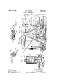
- Figure 1 is a view in side elevation of a power shovel constructed in accordance with my invention.
- Figure 2 is an enlarged plan view showing the platform and a portion of the dipper operating mechanism shown in Figure 1.
- Figure 3 is a detailed view of a pressure control valve which may be utilized in connection with the hydraulic system.
- Figure 4 is a vertical section of one form of hydraulic pump or motor which may be utilized as the main pressure pump, or as a motor for actuating the platform swinging mechanism, the boom hoisting mechanism and the dipper crowding mechanism.
- FIG. 5 is a detailed sectional view of the motor or pump,taken on line 55 of Figure 4.
- FIG. 6 is a detailed sectional view of hydraulic plunger and cylinder which is herein shown as actuating mechanism for certain clutches, brakes and the dipper trip control, as will hereinafter more fully appear.
- Figure 7 is a detailed sectional view of a four-way valve which is used as a controlling device for the several actuating and controlling elements of the machine.
- Figure 8 is an enlarged side view of the main frame showing details of the various control devices thereon.
- the shovel 4 is of the dipper type having a handle 5 provided with a rack 6, engaging a pinion 7 carried on shaft 7a journalled on boom 8.
- the boom is arranged as usual at the front of the main frame so as to be raised or lowered by suitable draft means, herein comprising a cable 10 wound about sheaves 11 and 12 carried on the end of the boom and on frame support 13 respectively, and having one end 14 wound on drum 15 on the main frame.
- suitable draft means herein comprising a cable 10 wound about sheaves 11 and 12 carried on the end of the boom and on frame support 13 respectively, and having one end 14 wound on drum 15 on the main frame.
- the power actuating devices and controlling means for said drum will hereinafter be more fully described.
- the dipper 4 is further connected for operation by means of a single cable 16 passed over a sheave 17 on the upper end of the boom 8 and wound upon a main operating drum 18.
- the driving motor 20 shown herein is of the usual multicylinder hydrocarbon type mounted on a transverse axis at the rear end of the turn-table 1.
- the main drive shaft 21 of the motor is connected through a pinion l9 and gear 22 to a shaft 23 arranged in a transverse axis, but in front of the motor.
- This shaft is arranged to drive a hydraulic pressure pump 25 of any suitable form, the pump herein disclosed being ofthe wellknown rotor type shown in detail in Figures 4 and 5, and consisting of a pair of meshed rotors 25a, 25a in casing 256, having inlet and outlet parts 250 and 25d arranged in the usual manner to produce a pressure on a liquid such as oil, when the rotors are driven.
- the shaft 23 also has operative connections for driving the main power drum 18 through pinion 26, gear 27 on shaft 28, gear 29 on shaft 30, and a clutch 31, at the opposite end of said shaft, afiording selectii e driving engagement between said shaft and drum 18 normally mounted loosely thereon.
- Operative connections are also afforded for driving the endless tread device 3 on the truck 2, herein consisting of a gear 35, operatively connected to the shaft 23 through gears 29, 27, 22, and loosely mounted on shaft 36.
- Reversible power connections are mounted on the shaft 36 herein consisting of a sliding clutch memher 37, adapted to be connected with a pair of oppositely connected gears 38 and 39, adapted to drive beveled gear 40 in opposite direction.
- Said beveled gear is mounted on the upper end of a vertically disposed shaft 41 concentric with the axis of movementof the turn-table or main frame 1.
- Suitable drive connections are afforded between the shaft 41 and the endless tread 3 on the truck, as for instance, through beveled gears 42, 43, longitudinal shaft 44 and transverse shaft 45, through mitre gears 45a, 45a, on shaft 46 carrying chain sprocket 47, engaging endless tread device 3 in the usual manner.
- the endless tread device may be driven in either direction by shaft clutch member 37 to engage either beveled gears 38 and 39 with shaft 36.
- a clutch member 48 is mounted on the end of clutch 37 to engage and disengage shaft 36 from drive gear 35 thereon, at will.
- the main hydraulic pump 25 is provided withan outlet or high pressure, pipe 50 which leads to a pressure valve 51, preferably arranged adjacent the front end of the main frame, as shown in Figures 1 and 2'.
- This pressure valve may be of any well-known form adapt ed to automatically maintain a predetermined pressure in the high pressure line 50. Details of a valve which may be utilized for this purpose are shown in Figure 3, in which a valve member 54 is adapted to be engaged with valve seat 55 under tension of a spring 56 in casing 57.
- the tension of the spring 56 is controlled by a threaded member 57 at the upper end of said casing, the adjustment of which will afford any predetermined pressure desired in the intake 59 connected with the high pressure pipe line 50. Any pressure in excess of the predetermined value causes the valve 54 to open and permit the liquid to escape through the outlet 60, connected to relief pipe 61.
- the said relief pipe returns rearwardly and upwardly to a storage or low pressure tank 62, preferably arranged at a relatively high position, as for instance, near the roof of the main frame, as shown in Figure 1, so that said tank is at or above the normal level of all of the hydraulically operated control members, including those mounted on the boom 8.
- the supply pipe 63 leads from the supply tank to the intake of the main hydraulic pump 25. By reason of the elevation of supply tank 62, as
- all of the pipes in turntable or main frame 1 on base 2 comprises a motor 65 (similar in construction to the pump 25, but now utilized as a motor) connected by pipes 66 and 67 to control valve 68.
- This valve is of the four-way type as shown in detail in Figure 6, and arranged so that pressure may be applied to either pipe 66 or 67 from the high pressure pipe line 50, depending upon the position of the control handle 69. It will be understood that when the valve is arranged so as to supply pressure to one of the pipes, the other pipe will be connected through the four-way valve to the relief or low pressure pipe 61, and vice versa.
- the hydraulic motor 65 controlled by valve 68 is designed to drive a pinion 70 meshed with gear 71 loosely mounted on shaft 28, and having a beveled gear 72 carried therewith, driving a beveled gear 73 on upright shaft 74.
- a pinion '75 is mounted on the lower end of shaft 74 and it meshes with an annular rack 76 fixed on the top of base 2 for swinging the turn-table 1 on said base. This swinging movement may be in either direction through the reversibility of motor 65 as described.
- a similar motor 75a is mounted adjacent the cable drum 15 upon which the boom elevating cable 10 is wound.
- This motor is controlled through valve 76a, similar in construction to four-way valve 68, and also connected between high pressure line 50 and low pressure line 61 as shown in Figure 2.
- Driving connection with drum 15 is afforded through shaft 77 and worm 78 meshed with worm gear 79 carried by the drum 15.
- Means for affording the crowding motion to the dipper handle 5 comprises a motor 80 similar in construction to motors 65 and 75a,
- control valve 104 herein shown as connected between the high pressure line 50 and the low pressure line 61 at the operators station adjacent control valves 68 and 84.
- the control valve 104 is of the same reversible type as valves 68, 76 and 84 previously mentioned, so that the clutch 31 may be readily engaged or disengaged at will.
- a brake band 110 is also provided as usual for the main operating drum 18 and is controlled through shaft 111 and lever 112 in the usual manner.
- I provide hydraulic plunger cylinder 113 of the same character as plunger 96 above described, for actuating the control lever 112 in opposite directions.
- the pressure pipes 118 and 119 lead to a valve 120 herein shown as disposed beneath the fioor of the mainframe adjacent the operators station and controlled by foot pedal 121. Feeding pipes 122 and 123 for said valve are connected to the high and low pressure pipe lines 50 andv 61 as usual.
- I also provide a novel means for tripping the dipper bottom 125, whereby the latch for said bottom may be disengaged in any position of the dipper in a much more positive manner than heretofore afforded by means of a flexible rope, chain or the like, leading from the dipper latch to the operators station.
- the tripping cable 127 is led forwardly about a drum 131 carried on the end of pinion shaft 7a.
- the drum 131 is substantially the same diameter as the passage line of said crowding pinion 7, so that the cable 127 will bGJVOlllld or unwound in step with the inward and outward movement of the dip-per handle 5 relative to the pinion 7.
- the arrangement is such that w-hen the plunger 129 is in its extreme position, sufflcient slack is provided for the rope 127 to permit the latch 126 to be locked in all permissible positions of the dipper.
- An auxiliary idler lever 133 is pivotally mounted on the boom adjacent its outer end and supports the rope 127 so as to afford a more direct longitudinal pull from latch 126 and reduces the amount of slack in said rope.
- the plunger 129 is actuated by its control lever 134 mounted on the main frame and connected therethrough to pipes 135 and 136 so as to proand latch 126 and thereby release the latter.
- a powers ovel a main frame, a boom, a dipper, and a hydraulic control system for said dipper including a pump, a high pressure line, a pressure valve, a low pressure line, and hydraulic di per actuating devices including a thrustin dfevice mounted on said boom and connecte between said high and low pressure line, and a liquid reservoir connected with'said low pressure line and disposed at the highest point in said hydraulic system, whereby all of said lines and actuating devices Will normally remain full of liquid during periods of inoperation of said hydraulic system.
Landscapes
- Engineering & Computer Science (AREA)
- Mechanical Engineering (AREA)
- Mining & Mineral Resources (AREA)
- Civil Engineering (AREA)
- General Engineering & Computer Science (AREA)
- Structural Engineering (AREA)
- Jib Cranes (AREA)
Description
May 9, 1933. J .D. RAUCH 3,907,442 v HYDRAULIC POWER SHOVEL Filed May 9, 1927 3 Sheets-Sheet 1 May 9, 1933. J. D; RAUCH 1,907, 2
HYDRAULIC POWER SHOVEL Filed May 9, 1927 '3 Sheets-Sheet 2 May 9, 1933. J. D. RAUCH 1,907,442
HYDRAULIC POWER SHOVEL Filed May 9,1927 3 Sheets-Sheet 5 g w i "3 :T
. v .r 1! 1 l d r I I 3 W r /A Zak/mass; v q
Patented May 9, 1933 UNITED STATES PATENT OFFICE JOHN D. MUCH, OF LIMA, OHIO, ASSIGNOR TO OHIO POWER SHOVEL COMPANY, OF LIMA, OHIO, A. CORPORATION OF OHIO HYDRAULIC POW'ER SHOVEL Application filed May 9,1927. Serial No. 189,849.
This invention relates to material handling devices such as power shovels, cranes and the like. The principal object of the invention is to provide an improved form of hydraulic actuating and controlling mechanism for operating the hoisting drums, turn-table, and.
other movable elements thereof. A further object of the invention is to provide an im proved form of dipper tripping mechanism. Other objects of the invention will appear from time to time as the description proceeds.
The invention will best be understood by referring to the accompanying drawings, in which Figure 1 is a view in side elevation of a power shovel constructed in accordance with my invention.
Figure 2 is an enlarged plan view showing the platform and a portion of the dipper operating mechanism shown in Figure 1.
Figure 3 is a detailed view of a pressure control valve which may be utilized in connection with the hydraulic system.
Figure 4 is a vertical section of one form of hydraulic pump or motor which may be utilized as the main pressure pump, or as a motor for actuating the platform swinging mechanism, the boom hoisting mechanism and the dipper crowding mechanism.
Figure 5 is a detailed sectional view of the motor or pump,taken on line 55 of Figure 4.
Figure 6 is a detailed sectional view of hydraulic plunger and cylinder which is herein shown as actuating mechanism for certain clutches, brakes and the dipper trip control, as will hereinafter more fully appear.-
Figure 7 is a detailed sectional view of a four-way valve which is used as a controlling device for the several actuating and controlling elements of the machine.
Figure 8 is an enlarged side view of the main frame showing details of the various control devices thereon.
Referring now to the details shown in the drawings, my invention is illustrated as applied to a power shovel having the motor and main operating mechanism carried on a frame or turn-table 1, which is pivotally mounted to swing on vertical axis upon a base 2, said base is provided with propelling mechanism, herein consisting of an'endless tread mechanism 3. The shovel 4 is of the dipper type having a handle 5 provided with a rack 6, engaging a pinion 7 carried on shaft 7a journalled on boom 8. The boom is arranged as usual at the front of the main frame so as to be raised or lowered by suitable draft means, herein comprising a cable 10 wound about sheaves 11 and 12 carried on the end of the boom and on frame support 13 respectively, and having one end 14 wound on drum 15 on the main frame. The power actuating devices and controlling means for said drum will hereinafter be more fully described. The dipper 4 is further connected for operation by means of a single cable 16 passed over a sheave 17 on the upper end of the boom 8 and wound upon a main operating drum 18.
The driving motor 20 shown herein is of the usual multicylinder hydrocarbon type mounted on a transverse axis at the rear end of the turn-table 1. The main drive shaft 21 of the motor is connected through a pinion l9 and gear 22 to a shaft 23 arranged in a transverse axis, but in front of the motor. This shaft is arranged to drive a hydraulic pressure pump 25 of any suitable form, the pump herein disclosed being ofthe wellknown rotor type shown in detail in Figures 4 and 5, and consisting of a pair of meshed rotors 25a, 25a in casing 256, having inlet and outlet parts 250 and 25d arranged in the usual manner to produce a pressure on a liquid such as oil, when the rotors are driven.
The shaft 23 also has operative connections for driving the main power drum 18 through pinion 26, gear 27 on shaft 28, gear 29 on shaft 30, and a clutch 31, at the opposite end of said shaft, afiording selectii e driving engagement between said shaft and drum 18 normally mounted loosely thereon. Operative connections are also afforded for driving the endless tread device 3 on the truck 2, herein consisting of a gear 35, operatively connected to the shaft 23 through gears 29, 27, 22, and loosely mounted on shaft 36. Reversible power connections are mounted on the shaft 36 herein consisting of a sliding clutch memher 37, adapted to be connected with a pair of oppositely connected gears 38 and 39, adapted to drive beveled gear 40 in opposite direction. Said beveled gear is mounted on the upper end of a vertically disposed shaft 41 concentric with the axis of movementof the turn-table or main frame 1. Suitable drive connections are afforded between the shaft 41 and the endless tread 3 on the truck, as for instance, through beveled gears 42, 43, longitudinal shaft 44 and transverse shaft 45, through mitre gears 45a, 45a, on shaft 46 carrying chain sprocket 47, engaging endless tread device 3 in the usual manner. As will be seen in Figure 2 the endless tread device may be driven in either direction by shaft clutch member 37 to engage either beveled gears 38 and 39 with shaft 36. A clutch member 48 is mounted on the end of clutch 37 to engage and disengage shaft 36 from drive gear 35 thereon, at will.
Referring now to hydraulic actuating and control mechanism which are utilized in connection with parts above described, the main hydraulic pump 25 is provided withan outlet or high pressure, pipe 50 which leads to a pressure valve 51, preferably arranged adjacent the front end of the main frame, as shown in Figures 1 and 2'. This pressure valve may be of any well-known form adapt ed to automatically maintain a predetermined pressure in the high pressure line 50. Details of a valve which may be utilized for this purpose are shown in Figure 3, in which a valve member 54 is adapted to be engaged with valve seat 55 under tension of a spring 56 in casing 57. The tension of the spring 56 is controlled by a threaded member 57 at the upper end of said casing, the adjustment of which will afford any predetermined pressure desired in the intake 59 connected with the high pressure pipe line 50. Any pressure in excess of the predetermined value causes the valve 54 to open and permit the liquid to escape through the outlet 60, connected to relief pipe 61. The said relief pipe returns rearwardly and upwardly to a storage or low pressure tank 62, preferably arranged at a relatively high position, as for instance, near the roof of the main frame, as shown in Figure 1, so that said tank is at or above the normal level of all of the hydraulically operated control members, including those mounted on the boom 8. The supply pipe 63 leads from the supply tank to the intake of the main hydraulic pump 25. By reason of the elevation of supply tank 62, as
, shown, it will be seen that all of the pipes in turntable or main frame 1 on base 2 comprises a motor 65 (similar in construction to the pump 25, but now utilized as a motor) connected by pipes 66 and 67 to control valve 68. This valve is of the four-way type as shown in detail in Figure 6, and arranged so that pressure may be applied to either pipe 66 or 67 from the high pressure pipe line 50, depending upon the position of the control handle 69. It will be understood that when the valve is arranged so as to supply pressure to one of the pipes, the other pipe will be connected through the four-way valve to the relief or low pressure pipe 61, and vice versa. The hydraulic motor 65 controlled by valve 68 is designed to drive a pinion 70 meshed with gear 71 loosely mounted on shaft 28, and having a beveled gear 72 carried therewith, driving a beveled gear 73 on upright shaft 74. A pinion '75 is mounted on the lower end of shaft 74 and it meshes with an annular rack 76 fixed on the top of base 2 for swinging the turn-table 1 on said base. This swinging movement may be in either direction through the reversibility of motor 65 as described.
A similar motor 75a is mounted adjacent the cable drum 15 upon which the boom elevating cable 10 is wound. This motor is controlled through valve 76a, similar in construction to four-way valve 68, and also connected between high pressure line 50 and low pressure line 61 as shown in Figure 2. Driving connection with drum 15 is afforded through shaft 77 and worm 78 meshed with worm gear 79 carried by the drum 15.
Means for affording the crowding motion to the dipper handle 5 comprises a motor 80 similar in construction to motors 65 and 75a,
A brake band 110 is also provided as usual for the main operating drum 18 and is controlled through shaft 111 and lever 112 in the usual manner. I provide hydraulic plunger cylinder 113 of the same character as plunger 96 above described, for actuating the control lever 112 in opposite directions. In the form shown, the pressure pipes 118 and 119 lead to a valve 120 herein shown as disposed beneath the fioor of the mainframe adjacent the operators station and controlled by foot pedal 121. Feeding pipes 122 and 123 for said valve are connected to the high and low pressure pipe lines 50 andv 61 as usual.
In case an additional power drum, asindicated in dotted lines 180, is desired, a duplicate set of controlling devices for its clutch and brake may be readily supplied therefor.
In connection with the present disclosure I also provide a novel means for tripping the dipper bottom 125, whereby the latch for said bottom may be disengaged in any position of the dipper in a much more positive manner than heretofore afforded by means of a flexible rope, chain or the like, leading from the dipper latch to the operators station.
In the present invention I connect flexible rope 127 to the dipper latch 126 as usual, but the rear or lower end of said cable is trained about the sheave 128 carried by hydraulic plunger 129 in cylinder 130 mounted on the boom 8 adjacent the crowding pinion 7. From the sheave 128, the tripping cable 127 is led forwardly about a drum 131 carried on the end of pinion shaft 7a. The drum 131 is substantially the same diameter as the passage line of said crowding pinion 7, so that the cable 127 will bGJVOlllld or unwound in step with the inward and outward movement of the dip-per handle 5 relative to the pinion 7. The arrangement is such that w-hen the plunger 129 is in its extreme position, sufflcient slack is provided for the rope 127 to permit the latch 126 to be locked in all permissible positions of the dipper. An auxiliary idler lever 133 is pivotally mounted on the boom adjacent its outer end and supports the rope 127 so as to afford a more direct longitudinal pull from latch 126 and reduces the amount of slack in said rope. When it is desired to release the latch, the plunger 129 is actuated by its control lever 134 mounted on the main frame and connected therethrough to pipes 135 and 136 so as to proand latch 126 and thereby release the latter.
Among the advantages of a hydraulically operated and controlled ower shovel .constructed as above describe is the great flexibility afi'orded through the various actuated and controlling devices described whereby full power can be applied instantly to each operation in either direction independently of the speed of the motor. Due to this increased flexibility I' find it convenient to utilize either a gasoline, Diesel-type, or electric motor in place of a steam engine, with extremely satisfactory results. The various actuating and controllin devices such as pumps or plungers may %e readily located at points of most direct application of power, while the control valves may all be placed at other convenient points, such as at a single operators station. My im roved con-. struction eliminates a large num er of gears, levers, shafts, etc., which are ordinarily required with mechanical controlling connections, and the various control handles of the hydraulic valves are far easier to manipulate than the usual form of mechanical clutch and brake mechanisms.
Furthermore, by reason of the reserve pressure supply maintained in. the pressure dome 64, it will be seen that at the critical time1 the dipper is under maximum stress in its igging operation, a eater roportion of the power of the drivfig mot dr may be directly applied to elevate the dipper through its direct geared connection to the main oisting drum 18, while additional reserve pressure previously built up in the hydraulic system will be available for actuating the'crowding and other auxiliary hydraulically operated mechanisms.
I claim as m invention:
In a powers ovel, a main frame, a boom, a dipper, and a hydraulic control system for said dipper including a pump, a high pressure line, a pressure valve, a low pressure line, and hydraulic di per actuating devices including a thrustin dfevice mounted on said boom and connecte between said high and low pressure line, and a liquid reservoir connected with'said low pressure line and disposed at the highest point in said hydraulic system, whereby all of said lines and actuating devices Will normally remain full of liquid during periods of inoperation of said hydraulic system.
Signed at Lima, Ohio, this 27th day of April 1927.
JOHN D. RAUCH.
duce a pull on rope 127 between cable 131
Priority Applications (1)
| Application Number | Priority Date | Filing Date | Title |
|---|---|---|---|
| US189849A US1907442A (en) | 1927-05-09 | 1927-05-09 | Hydraulic power shovel |
Applications Claiming Priority (1)
| Application Number | Priority Date | Filing Date | Title |
|---|---|---|---|
| US189849A US1907442A (en) | 1927-05-09 | 1927-05-09 | Hydraulic power shovel |
Publications (1)
| Publication Number | Publication Date |
|---|---|
| US1907442A true US1907442A (en) | 1933-05-09 |
Family
ID=22699016
Family Applications (1)
| Application Number | Title | Priority Date | Filing Date |
|---|---|---|---|
| US189849A Expired - Lifetime US1907442A (en) | 1927-05-09 | 1927-05-09 | Hydraulic power shovel |
Country Status (1)
| Country | Link |
|---|---|
| US (1) | US1907442A (en) |
Cited By (2)
| Publication number | Priority date | Publication date | Assignee | Title |
|---|---|---|---|---|
| DE950811C (en) * | 1942-08-11 | 1956-10-18 | Augsburg Nuernberg A G Zweigni | Crane driven by internal combustion engine, in particular diesel crane for grab operation |
| US3004674A (en) * | 1958-06-05 | 1961-10-17 | Robert M Griffith | Swivel support for shovel boom |
-
1927
- 1927-05-09 US US189849A patent/US1907442A/en not_active Expired - Lifetime
Cited By (2)
| Publication number | Priority date | Publication date | Assignee | Title |
|---|---|---|---|---|
| DE950811C (en) * | 1942-08-11 | 1956-10-18 | Augsburg Nuernberg A G Zweigni | Crane driven by internal combustion engine, in particular diesel crane for grab operation |
| US3004674A (en) * | 1958-06-05 | 1961-10-17 | Robert M Griffith | Swivel support for shovel boom |
Similar Documents
| Publication | Publication Date | Title |
|---|---|---|
| US2433598A (en) | Loading and unloading mechanism for motor vehicles | |
| US2418299A (en) | Power shovel | |
| US2323434A (en) | Mucking and loading machine | |
| US1907442A (en) | Hydraulic power shovel | |
| US1248600A (en) | Hoisting and dumping apparatus. | |
| US4143856A (en) | Split drive system for dragline with power interlock | |
| US1769991A (en) | Excavating apparatus | |
| US2416893A (en) | Portable loading machine | |
| US2339700A (en) | Power shovel | |
| CA1127600A (en) | Dual drive system for dragline with power interlock | |
| US2260539A (en) | Tractor shovel | |
| GB1516601A (en) | Power lowering system | |
| US2082018A (en) | Portable shovel | |
| US2648920A (en) | Carry-type scraper and digging front apron arrangement | |
| US3300190A (en) | Control arrangement | |
| US1527466A (en) | Dump-trailer power transmission | |
| US1555906A (en) | Drag-line excavator | |
| US1937432A (en) | Hydraulic crowder | |
| US1829569A (en) | Excavator crane | |
| US2354863A (en) | Load handling equipment | |
| US2737733A (en) | Trenching machine excavating control apparatus | |
| US1555907A (en) | Regenerative drag-line excavator | |
| US2140988A (en) | Power shovel | |
| US2082865A (en) | Well drilling mechanism | |
| US1380944A (en) | Back-filler |