US190087A - Improvementm corn-planters - Google Patents
Improvementm corn-planters Download PDFInfo
- Publication number
- US190087A US190087A US190087DA US190087A US 190087 A US190087 A US 190087A US 190087D A US190087D A US 190087DA US 190087 A US190087 A US 190087A
- Authority
- US
- United States
- Prior art keywords
- bar
- lever
- bars
- cross
- tongue
- Prior art date
- Legal status (The legal status is an assumption and is not a legal conclusion. Google has not performed a legal analysis and makes no representation as to the accuracy of the status listed.)
- Expired - Lifetime
Links
Images


Classifications
-
- A—HUMAN NECESSITIES
- A01—AGRICULTURE; FORESTRY; ANIMAL HUSBANDRY; HUNTING; TRAPPING; FISHING
- A01C—PLANTING; SOWING; FERTILISING
- A01C7/00—Sowing
- A01C7/20—Parts of seeders for conducting and depositing seed
- A01C7/208—Chassis; Coupling means to a tractor or the like; Lifting means; Side markers
Definitions
- N'PETERS PHOTO-LH'HOGRAFHER. WASHINGTON, U. C,
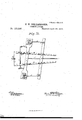
- Fig. 5 is a plan view of the rotary dropperdisk.
- Fig. 6 is a Vplan view of the tridentplateand attachments, which operate the -r0- tary disk S, (shown in Figs. 3 and 5.)
- Fig. 7 is a view of the upper* ⁇ end of; avdropper-tube or hollow post of the shoe, with the ianged plates by which it is pivoted to the cross-bar.
- Fig. 8 is a plan view ot' the T-shaped swivr eled coupling by which the sections are con nected.
- Fig. 9 is a rear view ofthe head of the foot-lever-U, its chains, andthe pivoted bar of the front section, showing the manner of their connection.
- Fig..10 is a sectionalv view of the track-clearer attachment, showing its connection with the tongue and the lever ⁇ for raising it.
- Fig. 11 is a ⁇ plan view of the under side of the front section of theplanter, showing the relative position of the parts in the zigzag or ⁇ oblique movement.
- A is the shoe of -the planter; A', its hollo post or dropper-tube.
- Fig. 1 shows the position of the *handlever l,with its latch-rod working over the circular toothed rack t' .on the side of one of the bars ,B of the tongue.
- the said lever l is rigidly attached to the ⁇ rock-shaft Z', which latter extends across the machine in rear of the main cross-bar, itsI rightend under the ⁇ right tongue-bar and its left end on the top of the ⁇ left tongue-bar. It is journaled in boxes ⁇ on said bars B.
- cross-bars c and c' are formed vby the ends of the two ⁇ draftrods c" and 0"', which extend, back, fromthe double-tree. 11"" and the block 12' at the intersection of the tongue-bars B, and are bent at right angles, and inserted down through their centers. c" also pivots the double-tree.
- Fig. 7 shows one form of pivoting the shoepost A'. It is made round at its top part, and has a flanged end and a collar below it, leaving a groove, g, between them. yThe flange-plates in Fig. 1l, which isless expensive ⁇ than the' other.
- r' is made circular, to allow it to pass easilyunder the ⁇ plate Q', which extends over it, and by which it is held in place, said plate being bolted to ⁇ the cross-bar C.
- the outside Hange r" is held to the bar by the pivot-bolt lo.
- the position of these parts in turning can be readily understood by the view given of thel under side of the frame in this ligure.
- the point of the shoe A which is attached to the forwarderossbar. o', is turned out'at right anglesin lthe same way ony either side, and is pivoted to the bar by the pivot-bolt 6".
- the distance can, of course, be varied withv the change in the position of the cross-furrows inpassing over the elevation.
- a a are the-dropper-boxes on leach end of the main cross-bar C.
- the dropping device consists of a rotary disk, S, with holes s through it for the passage of the grain, (see Figs-2, 3, and 5,) and angles 'i on the periphery of its under side, by which it is rotated.
- Figs. 3 and 4t the top. plate lo is also seen with its two vcut-offs rr. This plate extends over one-half of the disk S, and its depressed part p lits into a recess, p, inthe disk S, to retain it imposition while turning in the cavity formed for it in the bottom plate L ofthe boxa.
- the spring cut-offs r r are made of metal, and sloped off to a thin edge in front,
- b is a hand-lever forvoperatin g the droppers, of the ordinary kind, fulcrumed in a ring on the inner side of the box a.
- the pointed end of this hand-lever is inserted into the hole u in the end of the horizontal sliding lever b.
- the disk S In operating the droppers the disk S is rotated to the left by the operation of the pushpawls k la on the prongs Gr G.
- the middle prong Gr extends to the farther side of the disk S, is bent to one side, and has raised stops d' and d at opposite ends.
- the former operates in the thrust, and the latter in thedraw movement of theplate. F, alternately catching behind an angle, i, and holding the disk at each movement.
- the peculiar shape of prong G is such as to give certainty to the movements-ofthe disk S, and its arrestingstops d and d prevent any danger of registering incorrectly.
- the holes s are of even number, and the angles t' (of half the number) are odd.
- the prong G is bent down, so as not only to bring it away from the line of the' discharge-hole, but also to enable stop d to catch behind the proper angle.
- the couplingbar D is bolted to the centerv
- the foot-levers f' for raising each side of the front section, arefpivoted in Y-bolts on the top of the axle, and their front ends connected withthe rear ofthe tongue-bars by link-'rods m on each side, so that they can be operated independently of each other. (See Figs. l and 2.)
- an adjustable footlever,U is mounted in aY-bolt on the coupling-bar D, just forward of the axle. It ⁇ has a latch-lever, V, on the top, connected by la rod, V', with a slide, W, which Works inv a slot in the front end of lever U. This catches into the teeth of the uprightV rack X, also.
- lever U is formed with a cross-bar or- T-head, the ends-of which are turned up to form hooks, from which depend the chains k k each side of the coupling-bar. These are ⁇ connected at their lower ends with the ends of the vibratorybar Y, pivoted centrally on the rear side of the piece Y', which connects the rear ends of the tongue-bars B B.
- Fig. 1 shows their position when ready for operation. Extending downward and backward from midway of their pivoted points is an arm, a, with a ring in its end, which connects it (below block b"')'with a lifting-lever, b. In Fig. 10 a sectional view of the end of the left tongue-bar is shown, and a section of the track-clearer, with its lever attached.
- the vertical lifting-lever b passes up through a staple, 0, or a slot in the tongue-block b, as may be preferred. It is provided with' a stop, d", to hold it up when elevated or not in use.
- the hooks g are intended to rest on the ground, (when it is operated,) just inside of the line of the furrowing-shoes. (See Fig. 2.)
- a rotary dropper-disk, S constructed with an even number of holes, s', and an odd number of angles, z', in combination with a three-pronged or trident-shaped fork-plate, F, for operating the same, substantially as and for the purpose specified.
- Tridentplate F with its prongs G G G', and their accessory parts, consisting of pushpawl la, catch-paw'l k', and stops d and d, adapted to operate the rotary disk S, and arrest the motion of the same, as shown and described, for the purpose hereinbefore set forth.
- lever b In combination, lever b, slide-lever b', latch c, plate F, with its groove j, prongs G G- Gr', and their accessories, disk S, plate p, cut-offs r r, as described andset forth.
- Flange-plates ff in combination with groove g of a pivoted dropper-tube or shoepost, and the cross-bar G, as and for the purpose specified.
- the pivoted shoepost A' and shoe A in combination with the pivoted cross-bars C and c', operated substantially as set forth.
- Draft-rod c in combination with main cross-bar G, double-tree 11, tongue-block bf,
- Draft-rod c in combination with crossbar c', tongue-block b, draftsrod c, andtongue-bars B, as and for the purpose hereinbefore setforth.
- the T-shaped coupling-iron formed in one piece, with its central stem extending backward beneath and secured to the coupling-bar D, (by ring-bolts,) and with its 4lateral arms pivoted at the ends to the bars B B, connecting the bars B and D, all as and for the purpose specified.
Landscapes
- Life Sciences & Earth Sciences (AREA)
- Soil Sciences (AREA)
- Environmental Sciences (AREA)
- Soil Working Implements (AREA)
Description
, A 3 Sheets-Sheet. F. W. SHELLABARGER.
. conN-PLANMR.
No, 190,087, Patented Apr11z4,1a77.
N'PETERS, PHOTO-LH'HOGRAFHER. WASHINGTON, U. C,
rnhvionsw SHELLABARGER, OrMIAMi COUNTY, OHIO.
iMPRovfl-:MENT mcoRN-PLANTERS.
Specification 'forming part of Letters Patent N 0.190,087, dated April 24, 1877; applicationrled A Alwin 12, 1876,
To all whom it may concern: v'
BARGER, of the county of Miami, in the State of Ohio, have 4invented certain Improvements.
in Corn-Planters, oi' which the following-is a specification:
certainty, uniformity, and efficiency ofnperation, enable either dropper to be used vat pleas-` ure, regulate V.the depth of the furrows, and-` Fig. 5is a plan view of the rotary dropperdisk. Fig. 6 is a Vplan view of the tridentplateand attachments, which operate the -r0- tary disk S, (shown in Figs. 3 and 5.) Fig. 7 is a view of the upper*` end of; avdropper-tube or hollow post of the shoe, with the ianged plates by which it is pivoted to the cross-bar.
Fig. 8 is a plan view ot' the T-shaped swivr eled coupling by which the sections are con nected. Fig. 9 is a rear view ofthe head of the foot-lever-U, its chains, andthe pivoted bar of the front section, showing the manner of their connection. Fig..10 is a sectionalv view of the track-clearer attachment, showing its connection with the tongue and the lever` for raising it. Fig. 11 is a` plan view of the under side of the front section of theplanter, showing the relative position of the parts in the zigzag or` oblique movement. A is the shoe of -the planter; A', its hollo post or dropper-tube. The point of the shoe A and the upper endy of its post A' are both pivoted at their points of attachment to the ends of the two cross-bars O and c', so as to .allow of4 the movement of these cross-bars when operated 'by the lever Z` l' and rock- :shaft n n, whichV are connected to the main `cross-bar G. Y Y
Fig. 1 shows the position of the *handlever l,with its latch-rod working over the circular toothed rack t' .on the side of one of the bars ,B of the tongue. The said lever lis rigidly attached to the `rock-shaft Z', which latter extends across the machine in rear of the main cross-bar, itsI rightend under the` right tongue-bar and its left end on the top of the` left tongue-bar. It is journaled in boxes` on said bars B. Its endsare bentat reverse angles, upward and downward, and are flexiblyconnected with the cross-bar O by linkf Y v rods a n, which hook into them and into eye- My invention relateslto a double or two-horse corn-planter; and consists in constructing the same as fully describedv hereafter, to insure` bolts on the rear edge ofV said bars G. Lever l being thrown forward, the right arm of rock-` shaft l', by its Irod n, pushes the right end of cross bar C, with its dropper furroWing-shoe,
andv theright end of cross-bar` 0'., all forward,
while the armon the left end of said shaft L',
through its rod n on thatvside, pulls back the left ends of the `cross-bars with their dropper i and shoe. When the .handdever is thrown backward the positions are reversed. These oblique movements allow the `operator to drop the grain into the intersections of the furrows, whether they be straight or crooked, and
to turn the planter moreeasily by throwing the outside furrowing-shoe forward, of the other. The central pivots of cross-bars c and c' are formed vby the ends of the two` draftrods c" and 0"', which extend, back, fromthe double-tree. 11"" and the block 12' at the intersection of the tongue-bars B, and are bent at right angles, and inserted down through their centers. c" also pivots the double-tree. A
ring is turnedon the front end of 0"', whichv is slipped over the end of c" under block 11"', connecting both-rods together.` (See Fig. l.)
Fig. 7 shows one form of pivoting the shoepost A'. It is made round at its top part, and has a flanged end and a collar below it, leaving a groove, g, between them. yThe flange-plates in Fig. 1l, which isless expensive `than the' other.
' The top end of A' has iangesr' and r",
turned out on the two sides. r' is made circular, to allow it to pass easilyunder the `plate Q', which extends over it, and by which it is held in place, said plate being bolted to `the cross-bar C. The outside Hange r" is held to the bar by the pivot-bolt lo. The position of these parts in turning can be readily understood by the view given of thel under side of the frame in this ligure. The point of the shoe A, which is attached to the forwarderossbar. o', is turned out'at right anglesin lthe same way ony either side, and is pivoted to the bar by the pivot-bolt 6". In order to allow yof sufficient space for the movements of the In dropping the corn on the side of a hi'llL where one sideof the planter is considerably elevated above the-other, by throwingvthe shoe on the lower sideforward of the upper one the machine is kept more steady, as it lengthens the line of support on that side.
The distance can, of course, be varied withv the change in the position of the cross-furrows inpassing over the elevation.
a a are the-dropper-boxes on leach end of the main cross-bar C. The dropping device consists of a rotary disk, S, with holes s through it for the passage of the grain, (see Figs-2, 3, and 5,) and angles 'i on the periphery of its under side, by which it is rotated. In Figs. 3 and 4t the top. plate lo is also seen with its two vcut-offs rr. This plate extends over one-half of the disk S, and its depressed part p lits into a recess, p, inthe disk S, to retain it imposition while turning in the cavity formed for it in the bottom plate L ofthe boxa. The spring cut-offs r r are made of metal, and sloped off to a thin edge in front,
and pivoted with their inner ends in contact on the same rod. They are placed so that the line of division between them is coincident with the line of a circle on the plane of the disk, cutting` through the centers of the holes s. Should a kernel of corn become lodged under one of them the other will continue to operate, while in the single cut-ofi a lodgment of the kernel under it stops the operation of the cut-0E entirely.
b is a hand-lever forvoperatin g the droppers, of the ordinary kind, fulcrumed in a ring on the inner side of the box a. The pointed end of this hand-lever is inserted into the hole u in the end of the horizontal sliding lever b.
(See Fig. 6.) The endof' b' is lapped over on itself, to prevent the point of b from touching the bottom of the groove j in the trident-plate F, lwhen the two pieces are disconnected. c is a lock-latch, with holes e e', which allow the pins e e in d and b to project through them when it is shut down, as seen in Fig. 2. This latch is hinged to the edge of one of the sides d of the trident-plate F. The groove j allows the separate sliding bar b to move in it when the two pieces are notiu gear.
In operating the droppers the disk S is rotated to the left by the operation of the pushpawls k la on the prongs Gr G. The middle prong Gr extends to the farther side of the disk S, is bent to one side, and has raised stops d' and d at opposite ends. The former operates in the thrust, and the latter in thedraw movement of theplate. F, alternately catching behind an angle, i, and holding the disk at each movement. The peculiar shape of prong G is such as to give certainty to the movements-ofthe disk S, and its arrestingstops d and d prevent any danger of registering incorrectly. The holes s are of even number, and the angles t' (of half the number) are odd. The prong G is bent down, so as not only to bring it away from the line of the' discharge-hole, but also to enable stop d to catch behind the proper angle.
Between the two dropper-boxes a av is the attendant ldroppers seat E. This is' placed on the coupling-bar D, which extends forward over the cross-bar G, and is coupled to the tongue-bars B (between them) Yby the couplling-iron h. (Shownin detail, Fig. 8.) Thisiron, which is round and T-shaped, has its stem extending along under'4 the coupling-bar, to
which it is -swiveled by the eyebolts h. Its
head, extending acrossthe two tongue-bars,l
is'similarly pivotedvto them bythe eyebolts o. This coupling allows of the oscillation of the forward -section in any direction without affecting the droppers seat.
The couplingbar D is bolted to the centerv The foot-levers f', for raising each side of the front section, arefpivoted in Y-bolts on the top of the axle, and their front ends connected withthe rear ofthe tongue-bars by link-'rods m on each side, so that they can be operated independently of each other. (See Figs. l and 2.)
To regulate the depth for pressing the fun l rowing-shoes into the ground an adjustable footlever,U, is mounted in aY-bolt on the coupling-bar D, just forward of the axle. It `has a latch-lever, V, on the top, connected by la rod, V', with a slide, W, which Works inv a slot in the front end of lever U. This catches into the teeth of the uprightV rack X, also.
bolted on the top of said bar D. rThe front end of lever U is formed with a cross-bar or- T-head, the ends-of which are turned up to form hooks, from which depend the chains k k each side of the coupling-bar. These are `connected at their lower ends with the ends of the vibratorybar Y, pivoted centrally on the rear side of the piece Y', which connects the rear ends of the tongue-bars B B.
To operate this device the heel ot' the foot is placed on the end of foot-lever U, and the toe on the spring-latch or secondary lever V, to
withdraw the slide W, and adjust it to any desired height, while pressing down lever U. The undulatory motions of the front section and the relation of the parts are shown in Fig. 9, the dotted lines t t showing the up and-down movements of the piece Y', while the bar Y, pivoted to it by bolt Z, keeps its level position by the connections shown with the foot-lever U. The bolt Z and stem of coupling h form the pivots for the front section when subjected to up-and-down side movements. a is a round rod of iron, which forms the track-clearer attachment. It is pivoted at its middle part in eyebolts or staples at the front end of the tongue-bars B, and extends down on each side to the ground in front of the furrowng-shoes A. Its lower ends turn downward in the form of circular hooks, for the purpose of catching any stalks or other obstructions that may be in their way. Fig. 1 shows their position when ready for operation. Extending downward and backward from midway of their pivoted points is an arm, a, with a ring in its end, which connects it (below block b"')'with a lifting-lever, b. In Fig. 10 a sectional view of the end of the left tongue-bar is shown, and a section of the track-clearer, with its lever attached. vThe vertical lifting-lever b passes up through a staple, 0, or a slot in the tongue-block b, as may be preferred. It is provided with' a stop, d", to hold it up when elevated or not in use. The hooks g are intended to rest on the ground, (when it is operated,) just inside of the line of the furrowing-shoes. (See Fig. 2.)
I claim as my improvement- 1. The combination, in a planter, of a recessed dropper-plate and a cut-ott', consisting of two plates, r r, arranged to operate independently, but both simultaneously, in relation to the same hole, as and for the purpose set forth.
2. The combination of the plate p, the recessed dropper-plate S, and the two plates fr r, pivoted side by side to the plate p, and arranged to operate simultaneously in relation to the same hole, as set forth.
3. A rotary dropper-disk, S, constructed with an even number of holes, s', and an odd number of angles, z', in combination with a three-pronged or trident-shaped fork-plate, F, for operating the same, substantially as and for the purpose specified.
4. Tridentplate F, with its prongs G G G', and their accessory parts, consisting of pushpawl la, catch-paw'l k', and stops d and d, adapted to operate the rotary disk S, and arrest the motion of the same, as shown and described, for the purpose hereinbefore set forth.
5. The combination of the fork-plate, the disk S, operated thereby, the sliding plate b,
`and a latch, or its equivalent, whereby the two plates may be connected or disconnected, for the purpose set forth.
6. Latch c, with its holes e e', in combination with plate F and slide-lever b', with their pins e c, as and for the purpose speciiied.
7. The independent or detachable slide-1ever b', having its ends lapped over on itself, with a hole, u', in the overlapped part for the insertion of the end of the hand-lever b for operating it, and provided with a pin, or equivalent, for connecting it to the fork-plate ot' the dropper by latch c, substantially as shown and described, for the purpose set forth.
8. In combination, lever b, slide-lever b', latch c, plate F, with its groove j, prongs G G- Gr', and their accessories, disk S, plate p, cut-offs r r, as described andset forth.
9. Flange-plates ff, in combination with groove g of a pivoted dropper-tube or shoepost, and the cross-bar G, as and for the purpose specified.
10. In a two-horse corn-planter, withfurrowing-shoes attached to its front section, as
shown and specified, the pivoted shoepost A' and shoe A, in combination with the pivoted cross-bars C and c', operated substantially as set forth.
11. Draft-rod c, in combination with main cross-bar G, double-tree 11, tongue-block bf,
and tongue-bars B, as and for the purpose hereinbefore set forth.
12. Draft-rod c, in combination with crossbar c', tongue-block b, draftsrod c, andtongue-bars B, as and for the purpose hereinbefore setforth.
13. The long open stirrups u and n" and tongue-bars B, in combination with cross-bars C and c', with their pins n, for the purpose of allowing side motion to said cross-bars when operated, as shown and specied.
14.. The combination of the cross-bar O and the crank-lever l", turning in bearings on the bars B, connected ilexibly with the bar C by links a, and operating with said bar, substantially as and for the purpose specified.
15. In combination with the shoepost A', the retaining-plates q, anges r' and r", and cross-bar C, as shown and speciedl, for the purpose hereinbefore set forth.
16. The T-shaped coupling-iron formed in one piece, with its central stem extending backward beneath and secured to the coupling-bar D, (by ring-bolts,) and with its 4lateral arms pivoted at the ends to the bars B B, connecting the bars B and D, all as and for the purpose specified.
17. The forked coupling-bar D, bolted upon the top of the axle, and connected, by the braces m', with the rear of the same, as a means of strengthening this part, as hereinbefore set forth.
FLAVIOUS W. SHELLABARGER.
Attest:
B. C. CONVERSE,A J. O. BROWN.
Publications (1)
| Publication Number | Publication Date |
|---|---|
| US190087A true US190087A (en) | 1877-04-24 |
Family
ID=2259494
Family Applications (1)
| Application Number | Title | Priority Date | Filing Date |
|---|---|---|---|
| US190087D Expired - Lifetime US190087A (en) | Improvementm corn-planters |
Country Status (1)
| Country | Link |
|---|---|
| US (1) | US190087A (en) |
-
0
- US US190087D patent/US190087A/en not_active Expired - Lifetime
Similar Documents
| Publication | Publication Date | Title |
|---|---|---|
| US411470A (en) | Cotton chopping | |
| US242063A (en) | Signoe op one-half to william e | |
| US200415A (en) | Improvement in corn-planters | |
| US217083A (en) | Improvement in corn-planters | |
| US205020A (en) | Improvement in seed-planters | |
| US111826A (en) | Improvement in corn-planters | |
| US198254A (en) | Improvement in combined cotton cultivator and planter | |
| US363407A (en) | Corn-planter | |
| US265692A (en) | Corn-planter | |
| US185515A (en) | Improvement in corn-planters | |
| US323942A (en) | lucas | |
| US188502A (en) | Improvement in corn-row markers | |
| US219002A (en) | Improvement in combined drill and corn-planter | |
| US494926A (en) | Corn-planter | |
| US232689A (en) | Combined listing-plow and seed-planter | |
| US32792A (en) | Improvement in seed-drills | |
| US151600A (en) | Improvement in corn-planters | |
| US87885A (en) | Improvement in combined planter and cultivator | |
| US210214A (en) | Improvement in combined drill and corn-planter | |
| US111871A (en) | Improvement in combined agricultural implements | |
| US438058A (en) | Corn-planter | |
| US413311A (en) | Corn-planter | |
| US228068A (en) | Corn-planter | |
| US543530A (en) | Check-row planter and drill | |
| US353834A (en) | Corn-planter |