US1897874A - Optical system - Google Patents
Optical system Download PDFInfo
- Publication number
- US1897874A US1897874A US527780A US52778031A US1897874A US 1897874 A US1897874 A US 1897874A US 527780 A US527780 A US 527780A US 52778031 A US52778031 A US 52778031A US 1897874 A US1897874 A US 1897874A
- Authority
- US
- United States
- Prior art keywords
- images
- gauss
- lenses
- lens
- beam splitter
- Prior art date
- Legal status (The legal status is an assumption and is not a legal conclusion. Google has not performed a legal analysis and makes no representation as to the accuracy of the status listed.)
- Expired - Lifetime
Links
- 230000003287 optical effect Effects 0.000 title description 24
- 238000000926 separation method Methods 0.000 description 2
- 210000001691 amnion Anatomy 0.000 description 1
- 230000000295 complement effect Effects 0.000 description 1
- 230000007547 defect Effects 0.000 description 1
- 238000010586 diagram Methods 0.000 description 1
- 230000004048 modification Effects 0.000 description 1
- 238000012986 modification Methods 0.000 description 1
Images
Classifications
-
- G—PHYSICS
- G02—OPTICS
- G02B—OPTICAL ELEMENTS, SYSTEMS OR APPARATUS
- G02B27/00—Optical systems or apparatus not provided for by any of the groups G02B1/00 - G02B26/00, G02B30/00
- G02B27/10—Beam splitting or combining systems
- G02B27/1006—Beam splitting or combining systems for splitting or combining different wavelengths
- G02B27/1013—Beam splitting or combining systems for splitting or combining different wavelengths for colour or multispectral image sensors, e.g. splitting an image into monochromatic image components on respective sensors
-
- G—PHYSICS
- G02—OPTICS
- G02B—OPTICAL ELEMENTS, SYSTEMS OR APPARATUS
- G02B27/00—Optical systems or apparatus not provided for by any of the groups G02B1/00 - G02B26/00, G02B30/00
- G02B27/10—Beam splitting or combining systems
- G02B27/14—Beam splitting or combining systems operating by reflection only
- G02B27/144—Beam splitting or combining systems operating by reflection only using partially transparent surfaces without spectral selectivity
Definitions
- Another object of our invention is to provide an optical system for producing simul taneously two images of the same object field from the same viewpoint and in which the images are exactly registered on the film and are free from any defects caused by parallax or magnification differences.
- Our invention contemplates the provision of an optical system in which a beam splitter is used to divide the light from the object field and direct the divided beams through objective lenses, which are so constructed as to compensate for the difference in the opti cal paths through the beam splitter.
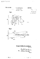
- FIG. 1 illustrates a combined lens and prism system embodying our invention.
- Figure 2 is a diagram illustrating how the path differences through the beam splitter are compensated for by properly positioning the Gauss planes of the objective lenses.
- the objective 1O hereinafter called the direct lens is positioned to receive light from an object at an infinite distance transmitted directly through the beam splitter 12 and to image this object in the plane
- the objective 11 hereinafter referred to as the side lens is positioned to receive light divided and reflected by the beam splitter 12, and to image the object in the plane of the film 13.
- the direct lens and the side lens are then rigidly secured to OF ROCHESTER, NEW YORK, ASSIGNORS TO A CORPORATION OF NEW OPTICAL SYSTEIVI 1931. Serial No. 527,780.
- the two images will be of the same object field and from the same point of view, and the two images will be in exact registration, by which we mean that the point of the object imaged on the axis of one lens will be imaged on the axis of the other lens.
- the two lenses l and 11 were identical, the images produced thereby would not be identical due to magnification differences caused by the dilference in the optical paths through the beam splitter.
- This difficulty 1S overcome by so constructing the two lenses that the difference in the optical paths through the beam splitter is exactly compensated for and the resulting images do not suffer because of magnification differences.
- FIG. 2 we have diagrammatically shown the path of a ray of light from an object 15 through the lenses to the plane of the film 13.
- a ray of light passing through the front Gauss point may be considered as entering the lens without diffraction, proceeding to the front Gauss point, and emerging in a parallel path from the back Gauss point, and it is because of this that the object distance used in lens formulae is measured from the front Gauss point and the image distance from the back Gauss point.
- the ray of light from the object 15 is shown as entering at the front Gauss point of the lens 11 and emerging from the back Gauss point to be imaged on the plane of the film 13.
- the front Gauss point lies in front of the back Gauss point.
- the lens has its front Gauss point behind its back Gauss point and consequently the object is imaged on the plane of the film l3, and the two images would have a magnification difference if the optical paths between the object 15 and the lenses were the same.
- the optical path of the light, which is directed to the lens 11 has an actual length greater than the light passing through the lens 10, and therefore, this difference in lengths of paths must be compensated for in order not to have magnification differences in their respective images.
- this compensation is accomplished by separating the front Gauss planes of the two lenses by a distance equal to the difference in the optical paths of the light reaching the respective lenses.
- an optical system constructed in accordance with our invention will give exact registration of images for all object distances, which images will be free from any magnification differences, as well as parallax, and the depth of focus of the system will be limited only by the black and white definition. This is true because the lenses are moved in assembly, their back Gauss planes are always the same distance from the plane of the film 13, and the optical distances of their front Gauss points from the face 14: of the beam splitter 12 are always equal.
- optical system of our invention may be used for projection purposes where it is desired to superimpose a plurality of images in a single projection beam.
- An optical system for producing on a film complemental images of an object field from the same point of view comprising a direct lens and a side lens, a beam splitter having a light dividing surface and reflecting surface in optical alinement with the direct and side lenses respectively, the said lenses having their back Gauss planes in the same plane and having their front Gauss planes separated by a distance equal to the difference of the light paths through the beam splitter.
- An optical system for producing simultaneously in asingle plane a plurality of images of the object field from accurately the same point of view comprising a beam splitter having a front face and a light dividing surface and reflecting surfaces, a plurality of lenses in optical alinement with the beams of divided light transmitted by said beam splitter, said lenses being mounted rigidly together and having their back Gauss points the same distance from the image plane and having their front Gauss points the same optical distance from the face of said beam splitter.
- An optical system for producing simultaneously in a single plane two images of an object field including two lenses of the same equivalent focal length positioned in optical paths of unequal length between the object field and the plane in which their respective images are formed, the algebraic difference of the separations of the Gauss planes of the two lenses being equal to the inequality of the two optical paths.
Landscapes
- Physics & Mathematics (AREA)
- Spectroscopy & Molecular Physics (AREA)
- General Physics & Mathematics (AREA)
- Optics & Photonics (AREA)
- Lenses (AREA)
Description
1933- F. E. TUTTLE ET AL 1,897,874
r OPTICAL SYSTEM x7? 1* Filed April 4, 1931 7/ I; X2; 70 17W x z 0%? F EWQMEAM,
amnion;
m lw Patented Feb. 14, 1933 UNITED STATES PATENT OFFICE FORDYCE E. TUTTLE AND FRED E. ALTMAN,
EASTMAN KODAK COMPANY, OF ROCHESTER, NEW YORK,
YORK
Application filed April 4,
it is desirable that the complementary images r of the film 13.
be taken simultaneously and from the same point of view, and that the images be of the same size and exactly positioned on the film.
It is an object of our invention to provide an optical system having an objective lens for each image which shall be focusable, and which shall have a depth of focus limited only by the black and white definition.
Another object of our invention is to provide an optical system for producing simul taneously two images of the same object field from the same viewpoint and in which the images are exactly registered on the film and are free from any defects caused by parallax or magnification differences.
Our invention contemplates the provision of an optical system in which a beam splitter is used to divide the light from the object field and direct the divided beams through objective lenses, which are so constructed as to compensate for the difference in the opti cal paths through the beam splitter.
Other objects and advantages of our invention will appear from the following description when read in connection with the accompanying drawing, and its scope will be pointed out in the appended claims.
Referring to the drawing-- Figure 1 illustrates a combined lens and prism system embodying our invention.
Figure 2 is a diagram illustrating how the path differences through the beam splitter are compensated for by properly positioning the Gauss planes of the objective lenses.
In Figure 1, the objective 1O hereinafter called the direct lens is positioned to receive light from an object at an infinite distance transmitted directly through the beam splitter 12 and to image this object in the plane The objective 11 hereinafter referred to as the side lens is positioned to receive light divided and reflected by the beam splitter 12, and to image the object in the plane of the film 13. The direct lens and the side lens are then rigidly secured to OF ROCHESTER, NEW YORK, ASSIGNORS TO A CORPORATION OF NEW OPTICAL SYSTEIVI 1931. Serial No. 527,780.
gether and are movably mounted for focusing. They have the same equivalent focal length and, therefore for equal object distances their focal planes will coincide throughout the range of focus of the lenses and the images formed will be exact duplicates. By using the beam splitter itwill be seen that the two images will be of the same object field and from the same point of view, and the two images will be in exact registration, by which we mean that the point of the object imaged on the axis of one lens will be imaged on the axis of the other lens. I If the two lenses l and 11 were identical, the images produced thereby would not be identical due to magnification differences caused by the dilference in the optical paths through the beam splitter. This difficulty 1S overcome by so constructing the two lenses that the difference in the optical paths through the beam splitter is exactly compensated for and the resulting images do not suffer because of magnification differences.
In Figure :2, we have diagrammatically shown the path of a ray of light from an object 15 through the lenses to the plane of the film 13. As is well known, a ray of light passing through the front Gauss point may be considered as entering the lens without diffraction, proceeding to the front Gauss point, and emerging in a parallel path from the back Gauss point, and it is because of this that the object distance used in lens formulae is measured from the front Gauss point and the image distance from the back Gauss point. In the drawing the ray of light from the object 15 is shown as entering at the front Gauss point of the lens 11 and emerging from the back Gauss point to be imaged on the plane of the film 13. In this case the front Gauss point lies in front of the back Gauss point. However, the lens has its front Gauss point behind its back Gauss point and consequently the object is imaged on the plane of the film l3, and the two images would have a magnification difference if the optical paths between the object 15 and the lenses were the same. In using the beam splitter 12 the optical path of the light, which is directed to the lens 11 has an actual length greater than the light passing through the lens 10, and therefore, this difference in lengths of paths must be compensated for in order not to have magnification differences in their respective images. In accordance with our invention, this compensation is accomplished by separating the front Gauss planes of the two lenses by a distance equal to the difference in the optical paths of the light reaching the respective lenses.
The types of objectives mentioned are well known and the particular formulae are immaterial. Other well known types of objective could be used. The adjustment of the position of the Gauss point by variation in the formula, particularly by changing the central separation, is well known to optical designers. Our invention consists in the choice of two objectives having the defined relative positions of their Gauss points and not in any particular formulae.
It will be seen that an optical system constructed in accordance with our invention will give exact registration of images for all object distances, which images will be free from any magnification differences, as well as parallax, and the depth of focus of the system will be limited only by the black and white definition. This is true because the lenses are moved in assembly, their back Gauss planes are always the same distance from the plane of the film 13, and the optical distances of their front Gauss points from the face 14: of the beam splitter 12 are always equal.
It will be obvious to those familiar with this art that the optical system of our invention may be used for projection purposes where it is desired to superimpose a plurality of images in a single projection beam.
l/Vhilewe have illustrated and described in detail one embodiment of our invention, in order to comply with the statutes, we do not wish to be limited to the exact arrangement described inasmuch as, in view of the disclosure, obvious modifications will suggest themselves to those familiar with this art without departing from the spirit of our invention, or the scope of the claims herein.
What we claim as new, and desire to secure by Letters Patent of the U. S. is:
1. An optical system for producing on a film complemental images of an object field from the same point of view comprising a direct lens and a side lens, a beam splitter having a light dividing surface and reflecting surface in optical alinement with the direct and side lenses respectively, the said lenses having their back Gauss planes in the same plane and having their front Gauss planes separated by a distance equal to the difference of the light paths through the beam splitter.
2. An optical system for producing simultaneously in asingle plane a plurality of images of the object field from accurately the same point of view, comprising a beam splitter having a front face and a light dividing surface and reflecting surfaces, a plurality of lenses in optical alinement with the beams of divided light transmitted by said beam splitter, said lenses being mounted rigidly together and having their back Gauss points the same distance from the image plane and having their front Gauss points the same optical distance from the face of said beam splitter.
3. An optical system for producing simultaneously in a single plane two images of an object field including two lenses of the same equivalent focal length positioned in optical paths of unequal length between the object field and the plane in which their respective images are formed, the algebraic difference of the separations of the Gauss planes of the two lenses being equal to the inequality of the two optical paths.
Signed at Rochester, New York, this 30th day of March, 1931.
FORDYCE E. TUTTLE. FRED E. ALTMAN.
Priority Applications (1)
| Application Number | Priority Date | Filing Date | Title |
|---|---|---|---|
| US527780A US1897874A (en) | 1931-04-04 | 1931-04-04 | Optical system |
Applications Claiming Priority (1)
| Application Number | Priority Date | Filing Date | Title |
|---|---|---|---|
| US527780A US1897874A (en) | 1931-04-04 | 1931-04-04 | Optical system |
Publications (1)
| Publication Number | Publication Date |
|---|---|
| US1897874A true US1897874A (en) | 1933-02-14 |
Family
ID=24102887
Family Applications (1)
| Application Number | Title | Priority Date | Filing Date |
|---|---|---|---|
| US527780A Expired - Lifetime US1897874A (en) | 1931-04-04 | 1931-04-04 | Optical system |
Country Status (1)
| Country | Link |
|---|---|
| US (1) | US1897874A (en) |
Cited By (2)
| Publication number | Priority date | Publication date | Assignee | Title |
|---|---|---|---|---|
| US3517327A (en) * | 1965-07-19 | 1970-06-23 | North American Rockwell | Laser output coupler |
| US5264951A (en) * | 1990-04-09 | 1993-11-23 | Victor Company Of Japan, Ltd. | Spatial light modulator system |
-
1931
- 1931-04-04 US US527780A patent/US1897874A/en not_active Expired - Lifetime
Cited By (2)
| Publication number | Priority date | Publication date | Assignee | Title |
|---|---|---|---|---|
| US3517327A (en) * | 1965-07-19 | 1970-06-23 | North American Rockwell | Laser output coupler |
| US5264951A (en) * | 1990-04-09 | 1993-11-23 | Victor Company Of Japan, Ltd. | Spatial light modulator system |
Similar Documents
| Publication | Publication Date | Title |
|---|---|---|
| US3388956A (en) | Photographic telephoto lenses of high telephoto power | |
| JPS5837523B2 (en) | Adjustable lens to focus | |
| US2284562A (en) | Mirror reflex camera with binocular eye level view finder | |
| US862354A (en) | Monocular camera. | |
| US3575082A (en) | Albada viewfinder having three lens components | |
| US1897874A (en) | Optical system | |
| US2983183A (en) | Beam combining prism | |
| US2950649A (en) | Interference microscope with transmitted illumination | |
| US2336330A (en) | Range finder | |
| US1114232A (en) | Stereoscope. | |
| US1490751A (en) | Lens system for taking and projecting pictures in natural colors | |
| US2862418A (en) | Inverted telephoto objective | |
| US3218908A (en) | Adjustable optical prism field splitter | |
| US2437032A (en) | Variable field range and view finder | |
| US1148222A (en) | Stereoscopic telemeter. | |
| US1497357A (en) | Method and system for producing a plurality of images | |
| US2384552A (en) | View and range finder | |
| US2313567A (en) | Range and depth of field finders for cameras | |
| US881127A (en) | Instrument for optically measuring distances. | |
| US1460706A (en) | Production of complemental images | |
| US2632357A (en) | Combined range and view finder | |
| US2478442A (en) | Orthopseudo range finder | |
| RU186634U1 (en) | Device for obtaining two stereoscopic images of small objects in one digital frame | |
| US1843007A (en) | Plural image optical system | |
| US886739A (en) | Device for focusing photographic cameras. |