US1897637A - Lift truck - Google Patents
Lift truck Download PDFInfo
- Publication number
- US1897637A US1897637A US556801A US55680131A US1897637A US 1897637 A US1897637 A US 1897637A US 556801 A US556801 A US 556801A US 55680131 A US55680131 A US 55680131A US 1897637 A US1897637 A US 1897637A
- Authority
- US
- United States
- Prior art keywords
- lifting
- frame
- lifting frame
- pins
- link
- Prior art date
- Legal status (The legal status is an assumption and is not a legal conclusion. Google has not performed a legal analysis and makes no representation as to the accuracy of the status listed.)
- Expired - Lifetime
Links
- 230000033001 locomotion Effects 0.000 description 18
- 230000007246 mechanism Effects 0.000 description 15
- 241000282472 Canis lupus familiaris Species 0.000 description 10
- 230000000994 depressogenic effect Effects 0.000 description 7
- 238000005266 casting Methods 0.000 description 5
- 210000005069 ears Anatomy 0.000 description 3
- 238000010276 construction Methods 0.000 description 2
- 230000005484 gravity Effects 0.000 description 2
- 230000010355 oscillation Effects 0.000 description 2
- 239000011435 rock Substances 0.000 description 2
- RYGMFSIKBFXOCR-UHFFFAOYSA-N Copper Chemical compound [Cu] RYGMFSIKBFXOCR-UHFFFAOYSA-N 0.000 description 1
- 102000012152 Securin Human genes 0.000 description 1
- 108010061477 Securin Proteins 0.000 description 1
- 208000027418 Wounds and injury Diseases 0.000 description 1
- 229940000425 combination drug Drugs 0.000 description 1
- 230000006378 damage Effects 0.000 description 1
- 230000000694 effects Effects 0.000 description 1
- 208000014674 injury Diseases 0.000 description 1
- 239000000463 material Substances 0.000 description 1
- 229920000136 polysorbate Polymers 0.000 description 1
Images


Classifications
-
- B—PERFORMING OPERATIONS; TRANSPORTING
- B62—LAND VEHICLES FOR TRAVELLING OTHERWISE THAN ON RAILS
- B62B—HAND-PROPELLED VEHICLES, e.g. HAND CARTS OR PERAMBULATORS; SLEDGES
- B62B3/00—Hand carts having more than one axis carrying transport wheels; Steering devices therefor; Equipment therefor
- B62B3/04—Hand carts having more than one axis carrying transport wheels; Steering devices therefor; Equipment therefor involving means for grappling or securing in place objects to be carried; Loading or unloading equipment
- B62B3/06—Hand carts having more than one axis carrying transport wheels; Steering devices therefor; Equipment therefor involving means for grappling or securing in place objects to be carried; Loading or unloading equipment for simply clearing the load from the ground
- B62B3/0625—Hand carts having more than one axis carrying transport wheels; Steering devices therefor; Equipment therefor involving means for grappling or securing in place objects to be carried; Loading or unloading equipment for simply clearing the load from the ground using rigid mechanical lifting mechanisms, e.g. levers, cams or gears
- B62B3/0631—Hand carts having more than one axis carrying transport wheels; Steering devices therefor; Equipment therefor involving means for grappling or securing in place objects to be carried; Loading or unloading equipment for simply clearing the load from the ground using rigid mechanical lifting mechanisms, e.g. levers, cams or gears with a parallelogram linkage
-
- B—PERFORMING OPERATIONS; TRANSPORTING
- B62—LAND VEHICLES FOR TRAVELLING OTHERWISE THAN ON RAILS
- B62B—HAND-PROPELLED VEHICLES, e.g. HAND CARTS OR PERAMBULATORS; SLEDGES
- B62B3/00—Hand carts having more than one axis carrying transport wheels; Steering devices therefor; Equipment therefor
- B62B3/04—Hand carts having more than one axis carrying transport wheels; Steering devices therefor; Equipment therefor involving means for grappling or securing in place objects to be carried; Loading or unloading equipment
- B62B3/06—Hand carts having more than one axis carrying transport wheels; Steering devices therefor; Equipment therefor involving means for grappling or securing in place objects to be carried; Loading or unloading equipment for simply clearing the load from the ground
- B62B3/0625—Hand carts having more than one axis carrying transport wheels; Steering devices therefor; Equipment therefor involving means for grappling or securing in place objects to be carried; Loading or unloading equipment for simply clearing the load from the ground using rigid mechanical lifting mechanisms, e.g. levers, cams or gears
Definitions
- Arar- O Arar- O, ILLINOIS, ASSIGNOR TO BARRETT-CRAVENS COM-.
- the present invention relates generally to lifttrucks of the type comprising a wheel supported main frame and a lifting frame or platform movably connected to the wheeled or mam frame.
- lifttrucks of the type comprising a wheel supported main frame and a lifting frame or platform movably connected to the wheeled or mam frame.
- frame or the truck When the lifting platform is in its lowered position frame or the truck is adapted to be backed under a platform or other support on which the load to ported has be transbeen placed, and then by operat ing suitable lifting mechanism the lifting platform can be raised to elevate from ported from one place to another.
- the present invention is concerned with such raising of the lifting in a plurality of lift trucks where the frame 1s accomplished steps, such trucks bem generally designated as multi-lift trucks.
- the present invention contemplates a vertically main frame hook which successively engages portions of rack means formed as nent part of the lifting frame ranged that the successively tions are brought substantially to position to at the beginnin.
- present invention swinging handle pivoted to the and operating a lifting link or different a permaand so arengaged porthe same be engaged by the lifting hook g of each llfting step.
- the present invention also con templates Serial No. ssasoi.
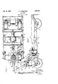
- Figure 1 is a vertical elevation of one form of my improved lift truck, certain parts be ing broken away in order to show the lifting and holding mechanism;
- Figure 2 is a top plan view of the lift truck shown in Figure 1;
- Figure 3 is a vertical elevation of a moditied form of lift truck embodying the principles of the present invention, certain parts of the truck being broken away in order to show more clearly certain details of the lifting mechanism;
- Figure 4 is a top plan view of the truck shown in Figure 3;
- FIG. 5 is an enlarged perspective view of one of the holding rack bars utilized in the truck shown in Figure 3 to hold the lifting frame in any one of its elevated positions;
- Figures 6 and and plan views modified form of ing the lifting mechanism out of engagementwith the lifting frame in order to allow the latter to lower;
- Figures 8 and 9 are also fragmentary elevation and plan views illustrating a still further modified form of releasing mechanism for the lifting means.
- the reference numeral 1 indicates in its entirety the main or wheeled supporting frame.
- the main frame 1 includes side bars 2 connected together at their rear ends by an angle bar 3 and at their forward ends by a cross head 6.
- the rearmost endportions of the side bar 2 are downturned, as best shown in Figure 1, and are apertured to receive an axle shaft 7 upon which the rear supporting wheels 8 are journaled.
- the forward ends of the side bars 2 are connected to the cross head 6 by bolts 10 and 11.
- the lifting frame is indicated in its entirety by the reference numeral 15 and, like the main frame 1, consists of a pair of side bars 16 connected together at their rear ends by an angle bar 18 and at their front ends by a T bar 19.
- the lifting frame 15 is pivotally connected with the main frame 1 so as to swing upwardly and forwardly with respect thereto.
- Connecting means between the main and lifting frames comprises swinging links preferably arranged in pairs.
- the forward pair of swinging links is designated by the reference numeral 21 and, as seen in Figures 1 and 2, each link 21 is pivotally mounted on the bolt 10 secured to the cross head 6 and is connected by a bolt 22 to the forward end of the side bars 16.
- the rear links are designated by the reference character 25, each of these links being journaled on the axle shaft 7 and connected together by transverse journal means 26 seated in the apex: of the angle bar 18, as clearly disclosed and claimed in Patent No. 1,773,935, issued August 26, 1930, to Arthur M. Barret
- the cross head 6 is provided with a portion 30 carrying a vertical bore in which a. king bolt (not shown) is jounaled.
- the king bolt carries a pair of supporting and steering wheels 31 at its lower end and at its upper end a king bolt cap 33 including a pair of apertured forwardly extending lugs 35 carrying a pivot bolt or pin 36.
- the lifting mechanism for raising the lifting frame 15 includes a lifting and steering handle 38 includin spaced bars 39 at its lower end pivoted On the pivot pin 36 for swinging movement in a vertical plane.
- the handle 38 is also operative to turn the king bolt and urge the wheels 31 to steer the truck.
- a curved lifting lever 40 is also pivoted on the pivot pin 36 and is formed with a loop portion 41 and a hook portion 42, the latter being adapted to be latched to the lifting handle 38 by means of a dog or detent ll.
- the present in"- vention provides a two-part lifting link 50, the upper end of which includes an eye 51 arranged to embrace the lifting lever H) and pivotally connected with the lower portion of the lifting link by a vertical pivot bolt 53.
- the function of the vertical bolt 53 is to provide for different lateral positions in which the lifting handle 38 may be when it is desired to raise the lifting frame.
- the lower end of the link is formed somewhat of a hook, as indicated by the reference numeral 55. The purpose of the hook portion 55 is to engage the lifting frame and elevate the same when the lifting handle 38 and the lifting link 50 are oscillated.
- the lifting frame 15 carries a pair of castings 57 and 58 riveted or bolted to the transverse T bar 19, the latter being welded or otherwise secured to the side bars 16 of the lifting frame 15.
- a pair of plates 60 and 61 are provided by the castings 57 and 58.
- the plates 60 and 61 are spaced apart an amount slightly in excess of the lifting link 50, as best shown in Figure 2, and of lower depending portions 60a and 61a which carry a plurality of pins 63 spaced apart in equal amounts and arranged in a generally downwardly and rearwardly extending curve.
- the lifting platform 15 is held in any one of its raised positions by means of a pair of rack bars 67 and 68 having rear journal bosses 69 and 70 pivotally supported by a transverse fined shaft 71 secured to the main frame 1.
- rack bars 67 and 68 extend forwardly and upwardly from their journal support on the fixed shaft 71 in a direction to bring them alongside the lifting link 50, both of which are positioned approximately in tangential relationship to the arc of movement of the lifting frame 15 about the forward pivotal support 10.
- the rack bars 67 and 68 are positioned outside the plates 60 and 61, as shown in Figure 2.
- a lug or plate portion is provided on each of the castings 57 and 58 and are arranged outside of the rack bars 67 and 68 and the plates 60 and 61, these lugs or plate portions being indicated by the reference numerals 73 and 74:-
- Each of the rack or holding bars have a pair of notches in its lower surface, these notches being staggered with respect to each other, as shown in Figure 1.
- the notches in the rack bar 67 are indicated by the reference characters a and b and the notches in the other rark bar 68 are designated by the reference characters 0 and cl.
- a pin is carried by the plate portions 73 and 60 formed on the casting member 57, and a similar pin is carried by the plate portions 61 and 74 formed on the other casting 58,
- the plate portions and the pins are so arpins, and for this purpose the T bar 19 may be formed with a notch 83 as indicated in Figure 1.
- the rack bar 67 overlies the pin 80 and the rack bar 68 overlies the pin 81.
- the operation of the lifting truck just described is substantially as follows.
- the lifting handle 38 When the lifting handle 38 is rocked rearwardly a sufiicient amount to cause the detent 44; to en gage the hooked end 12 of the lifting lever 40, a downward swinging movement of the lifting handle 38 will exert a direct forward and upward pull on the lifting link 50, the eye member 51 thereof moving substantially vertically in a line with the steering axis as defined by the king post.
- the resulting upward movement or oscillation of the lifting link 50, the lower hooked end 55 of which engages the first pin 63 carried by the plates 60 .nd 61 on the lifting frame, raises the lifting rame through the first is step at which time pin 81 on the right lianc side of the truck ngages the notch (Z formed on the lower surace of the right hand rack bar 68.
- This rack ar therefore holds the lifting frame in its rst elevated position.
- the upward movement of the lifting frame 15 causes the second pin 63 to occupy a position substantially the same as the position formerly occupied by the first pin 63 when the lifting frame was in its lowermost position. Therefore the lifting handle 38 can be raised to cause the lifting link 50 to lower, whereby the hook 55 will be engaged ver the second pin 63.
- the lifting link 50 will be pulled upwardly to raise the lifting platform 15 through the second step.
- the pin 81 will leave the notch (Z on the right hand rack bar 68 and will occupy a position substantially midway between the notch (Z and the notch 0.
- the pin 80 on the left hand side of the truck and with which the left hand rack bar 67 cooperates will be in a position to be engaged by the notch Z) on the rack bar 67.
- the left hand rack bar 67 and its cooperating pin 80 thus holes the lifting frame 15 in raised position.
- This second raising step brings the third pin 63 substanoccupied by the second pin which, as pointed out above, is substantially the same as the position occupied by the first pin before the lifting platform was raised.
- Tl e handle 38 is again raised to cause the lifting link to lower and to engage the third pin 63, whereupon the lifting handle 38 can be swung downwardly a third time to raise the lifting platform through its third lifting step.
- the pin 80 leaves the notch Z) on the rack bar 67 and takes a position substantially midway between the notch 6 and the notch a, but at this time the pin 81 on the other side of the truck will be moved from its half-way position between the notch (Z and the notch 0 into a position where the pin 81 will be engaged by the notch c on the right hand rack bar 88. This holds the lifting frame in its elevated position for the third lifting step.
- the fourth pin 63 is then brought to a position where it can be engaged by the hooked end 55 of the lifting link when the lifting handle 38 is swung upwardly.
- the lifting handle 38 may then be swung downwardly again to raise the lifting platform to its fourth lifting step, which 'iovement causes the pin 81 to leave the notch c on the rack bar 68 but at the same time causes the pin 80 on the left and side of the truck to be engaged by the notch a in the left hand rack bar 67.
- the lifting frame 15 is held in its uppermost raised position.
- the pins 80 and 81 act as pawls or fixed abutments on the lifting frame, which pawls or fixed abutments cooperate with the two rack or ratchet bars and 68 carried by the main frame to hold the lifting frame in any one of its raised positions.
- the staggered notch arrangement is that a number of steps can be provided for without necessitating rack or ratchet means havin too fine 'or too small teeth or notches, it b g understood that lift trucks of the present t, as are often subjected to quite heavy loads so that the means for holding the lifting plaform in raised position must be strong and sturdy and positive in its operation.
- the detent l4 can be swung upwardly to release the same from the li ting lever 10, whereupon the handle 38 can be swung freely and used as a tongue to pull and steer the truck from one place to another.
- each pin 63 occupies a position substantially the same as that occupied by the next preceding pin, this operation being desirable in order that the hooked end can readily engage the next pin to raise the lifting platform to the next lifting step.
- the pins 63 must be arranged substantially on a curve having the same radius as the radius of the are through which the lifting frame swings in its upward and forward raising movement, this radius being determined by the length of the links 21 and 25, but in order to bring the pins successively to the same point relative to the main frame the center of curvature of the arc of the pins 83 is above the pins whereas the center of arc movement of the lifting frame 15 is below the points of connection between the links and the lifting frame.
- the lifting link 50 should be raised slightly in advance of the rack bars 67 and 68 so that the hooked end thereof will not be caught on any of the pins 63 as the lifting frame 15 lowers after the rack bars 67 and 68 have been fully disengaged.
- the .neans l have provided to this end comprises a shaft 90 journaled on the main frame by means of suitable ears or lugs 91 formed on the head 6. Near one end of this shaft 90 a foot pedal 98 is provided.
- cams 95 and 96 are secured by set screws or the like to the shaft 90 and are positioned directly underneath the forwardmost ends of the An intermediate cain member 9! s also secured to the shaft 90, as by a set screw or the like, and this cam is positioned directly underneath the lifting link 50, see Figure 2, As best shown cam 9? which raises the lifting link 50 out.
- N f 0 only one of the rack bars 67 and 68 is operative at any one time to hold the lifting frame in raised position, it is necessary to hold both of hem a vay from the pins 80 and S1 order to permit the lifting frame to lower the entire distance.
- a spring 100 is biased between the top of the cross head 6 and the foot pedal 93 to hold the same normally in upper position, thereby holding the cams of operative engagement 9:", 96 and 9'? o with the lifting link 50 and the rack bars 67 and 68.
- the cross head 6 is also provit or with a detent 101 pivoted thereto by a pin 102 passing through the detent and carried by suitable lugs 10% carried by the cross head.
- a spring 106 serves to urge the detent 101 outwardly, the detent being provided with limit means in the form of an adjustable set screw 108 which restrains the detent 101 from moving too far away from the cross head 6.
- a laterally projecting abutment 110 is formed on the detent 101 and is positioned to be engaged behind a hook portion 111 formed on the foot pedal 93, as best shown in Figure 1.
- the hook pedal 93 is held in position to release the lifting link and the rack bars.
- the lifting frame has fully lowered and it is desired to allow the lifting link 50 and the rack bars 6? and 68 to move into operative engagement with the associated pins the operator steps on the detent 101 and presses the same inwardly to release the projecting abutment 110 from the hook 111 on the foot pedal 93, whereupon the spring swings the foot pedal 93 upwardly and lowers the cams 95, 96 and 97.
- the truck is provided with some form of check 115, such as ahydraulic cylinder and piston arrangement, for the purpose of controlling the descent of the lifting frame and preventing injury to the truck and to the load carried thereby as would result if the lifting frame 15 were allowed to descend too rapidly.
- the check 115 may be of any suitable construction.
- the check 115 is arranged for operation be tween the cross members 3 and 19, the former being carried by the main frame and the latter being carried by the lifting frame.
- FIGs 3 to 5 illustrate a truck embodying the same lifting mechanism shown in Figures 1 and 2 but which is provided with a somewhat dilferent arrangement for holding the lifting frame 15 in raised position at the end of each lifting step.
- a pair of rack or ratchet bars 120 and 121 are pivoted to the lifting frame by means of studs 123.
- the rack bars 120 and 121 are suitably connected to swing together by means of a connecting bar 124 suitably secured to each of the bars.
- [1 pin 126 is carried by each of the side bars 2 of the main frame 1 and these two pins serve as a pawl or abutment means with which suitably formed notches on the rack bars 120 and 121 cooperate to hold the lifting frame in raised position.
- the pins 126 serve the same purpose as the pins 80 and 81 shown in Figures 1 and 2.
- the left hand rack bar 120 is shown in-detail in Figure 5. At. its forward end the bar 120 is provided with a boss 130 which is suitably apertured,
- the rear portion of the bar 120 is suitably formed to provide a plurality of notches, three in the present instant, being indicated by the reference characters e, f and 9. These notches are preferably formed in the material of the bar itself, the bar being cut away or suitably cast to provide an intermediate portion 133 in which the notches e, f and g are formed.
- the bar 120 is also provided with a longitudinal passage or groove 134 which extends along the notches e, f and g and serves as a bypass along them.
- the top wall of the passage or groove 134 is given a downwarr; curvature, as indicated at 136, and the forward end of the groove 134 is closed by means of a pivoted dog 137 equipped with a spring 133 which urges the lower end of the dog 137 against the intermediate portion 133 of the bar 120.
- the pivoted detent or dog is mounted in a suitably formed transverse recess in the bar, the spring 138 being biased between one wall of the recess and the dog or detent 137.
- the latter is pivoted to the bar 120 by means of a pivot stud 140.
- the bar 120 is also provided with a depending lug 141 which is apertured to receive the connecting bar 124 leading to the other rack bar 121 see Figure 4.
- the lifting frame was held in its uppermost position by one of the rack bars, the lift truck shown in Figures 3 and is provided with a separate latch 145 pivoted to the cross head 6 by means of a s-..aft 146 carriedby pair of ears or lugs 147 for e l integral with the cross head e t 145 is provided with a hooked end 149 which is adapted to engage over a 1 0 carried by a suitable shaft 151 a air of lugs 153 formed on a riv ted or otherwise secured to ie latch 145 includes a lower pro ection 155 which receives a ct screw 156 which serves 1 g s '11 position to engage the if 'ng frame when the latb :evated to its upper position.
- the notches g engage the fixed pins 126 on the main frame and thus hold the lifting frame in its first position.
- the lifting handle is then raised and again lowered which causes the hooked end of the lifting link to engage the second of the pins 63 and raise the lifting platform another step to cause the second notch 7" formed on each of the holding bars to engage the fixed pin 126.
- this operation is repeat-ed, the notch s c then engaging the fixed pins 126 to hold the lifting frame up.
- the rack bars 120 and 121 are then moved forward an amount sufficient to cause the pins 126 on the main frame to clear the rear ends of the intermediate portions 133.
- the rack bars 120 and 121 then pivot downwardly about the pivot studs 123 until the upper edges 136 of the rack bars rest 011 the pins 126. When in this position, the pins 126 are then opposite the entrance to the groove or passage 134.
- the lifting platform is released by disengaging the latch 145 from the roller 150 on the lifting frame, the latter lowers under the action of gravity, being checked in its descent by the check 115, and as the lifting frame lowers the latch bars 120 and 121 move rearwardly, the pins 126 entering the grooves 134. Near the end of their rearward movement due to the lowering of the lifting frame the rack bars have moved rearwardly a sufficient amount to cause the dogs 137 to encounter the fixed ends or studs 126.
- FIGs 3 and 4 illustrate the means for releasing the latch 145 and raising the lifting link 50 which is somewhat different in some respects than the releasing means shown in Figures 1 and 2.
- a foot pedal 160 is shown as journaled upon the same shaft 1 16 upon which the latch 1-15 is mounted.
- the foot pedal 160 includes a pair of lateral extensions 163 and 16 1, the former extending underneath a small projection 165 on one side of the latch 14:5 and the latter extension 164 projecting to a point underneath the link 50.
- the projection 163 raises the latch 1 15 and the projection 1641 raises the lifting link 50.
- these projections are so arranged that the lifting link is raised slightly in advance of the latch 1 15.
- the foot pedal 160 is arranged to be held in depressed position by means of the detent 101 described in detail above.
- FIGs 6 and 7 illustrate a slightly different form of release mechanism for disengaging the lifting link 50 from the pins 63.
- the plates and 61 are shown as provided with rearward extension 170 which carries a pivot pin 171 upon which a forwardly extending curved lever 172 is pivoted.
- This lever has a plurality of notches 173 which are adapted to embrace the pins 63, and portions between the notches 173 are adapted to be projected between the pins 63 for the purpose of moving the end 55 of the lifting link 50 out of engagement with the pins 63 when the lever 172 is swung to its upper position.
- the lever 172 merely serving to fill the space between the pins 63 to prevent the link 50 from becoming engaged with any of them as the lifting platform is being lowered.
- Figure 6 illustrates one form of moving the lever 172 upwardly at the same time the holding means for the lifting platform is released.
- the cross head 6 in Figure 7 is shown as provided with a plurality of rearwardly extending ears or lugs 175 in which is carried a suitable shaft 17 6.
- a foot pedal 180 is rigidly secured to the shaft 17 6, the latter also carrying a cam 181 formed with an abutment portion 182.
- the lever 172 is adapted to be raised by means of a second lever 185 having a lower and laterally extending portion 186 arranged to engage underneath the lever 172 and raise the same and an upper projecting arm 187 cooperating with the cam 181.
- Figure 6 because the releasing mechanism shown in Figure 6 is applicable to either the lift truck shown in Figure 1 or the lift truck shown in Figure 3.
- the shaft 17 6 When used with the truck shown in Figure 1 the shaft 17 6 carries the cams 95 and 96 for lifting the rack bars 67 and 68 out of holding position, and when used with the truck shown in Figure 3, the shaft 176 carries the latch 1 15 loosely mounted thereon, the foot pedal 180 then.
- the cam 181 is so timed that the lever 185 is raised slightly in advance of the release of the other holding means, and the cam is so formed that further rotation of the shaft 176 is permitted without causing further movement of the lever 185.
- Figures 8 and 9 illustrate a further operat ing means for swinging the lever 172 upwardly to release the lifting link 50.
- the foot pedal 190 includes a depending arm 191 and is fixed to the shaft 176.
- a lever 193 is loosely journaled on the shaft 176 and includes a lateral projection 194: which extends to a point underneath the releasing lever 172, as in the case of the structure shown in Figure 6.
- the lever 193 includes a projection 196 arranged opposite the arm 191, and a spring 198 is biased between these two parts.
- the releasing mechanism shown in Figure 8 is adapted to be used in connection with either of the forms shown in Figures 1 and 3.
- the shaft 176 shown in Figure 8 may operate a latch 145, such as shown in Figure 3, or it may operate cams such as shown at 95 and 96 in Figure 2.
- the foot pedal 190 with its arm 191 is arranged to first compress the spring 198 to raise the lever 172, whereupon further movement of the foot pedal causes the disengagement of the hold ing means associated with the lifting truck, this further movement of the foot pedal having no effect upon the lever 193 or the lever 172 other than to further compress the spring 198.
- the foot pedal may be held in depressed position by the pivoted detent 101.
- a lift truck comprising, in combination, main and lifting frames, lifting means carried by the main frame and operable to raise the lifting frame relatively thereto, and means for holding the lifting frame in a plurality of elevated positions comprising a pair of notched rack bars, means pivoting said bars to the main frame, a pair of pins, one cooperating with one of said rack bars and the other cooperating with the other of said rack bars, and means securin the pins to the lifting frame.
- a lift truck comprising, in combination, a wheel supported main frame including a transverse head and its forward end, a lifting frame pivoted to the main frame to swing upwardly, means carried by said head and cooperating with the lifting frame to raise the same, means for holding the lifting frame in raised position comprising a rack bar pivoted to the main frame and extending forwardly and upwardly therefrom to a point near said head and a fixed abutment carried by the lifting frame and engaging the rack bar to hold the lifting frame in raised position, and means carried by said head for moving the rack bar out of engagement with said fixed abutment to permit the lifting frame to lower.
- a multi-lift truck comprising the combination with main and lifting frames of lifting means for raising the lifting frame relative to the main frame, said means comprising a vertically swin ing lever pivoted to the main frame, a lifting link connected at its forward end with said swinging lever and provided at its rear end with a hook portion, a pair of spaced plates fixedly secured to the lifting frame and positioned on either side of said lifting link, and a plurality of pins carried by said plates in spaced apart relationship, the hook portion of said lifting link cooperating with said pins to raise the lifting platform in a plurality of steps, means to hold the lifting platform in raised position, and means acting to release said holding means and also said lifting link from engagement with said pins;
- a lift truck comprising, in combina tion, main and lifting frames, lifting means for raising he lifting frame relative to the main frame, said means comprising a vertically swinging handle on the main frame, a lifting link pivotally connected therewith and adapted to be oscillated thereby from a lower position to an upper position, said lifting linl' having hook at'its lower end, and means carried by the lifting frame and adapted to be by the hooked end of said lifting link, said last nan ed means being arranged in such a line that the hooked end engages successive portions thereof from approximately the same lower position during the raising operation, and means arranged to hold the lifting frame in a plurality of elevated positions.
- a wheeled main frame in combination, a wheeled main frame, a lifting frame pivotally connected with the main frame to swing forwardly and upwardly pair of studs carried by said plates and 6X tending laterally therefrom in opposite directions, a shaft fixed to the main frame, a pair of rack bars journaled on said shaft and respectively positioned alongside of said plates, said rack bars being provided with notches to cooperate respectively with said two studs, the notches on one bar being staggered with respect to the notches on the other bar whereby each bar and its associated stud are alternately operable to retain the lifting frame in elevated position, including pins carried by the main frame and cooperating with the upper ends of said rack bars to release said b s from engagement with said studs, and means associated with said last mentioned means for releasing the lifting link from engagement with said pins, whereby the lifting frame is permitted to lower.
- a multi-lift truck comprising main and lifting frames, means connecting the lifting frame to the main frame to swing forwardly and upwardly, lifting means for raising the lifting frame relative to the main frame, said means comprising a lifting link positioned substantiall tangentially with respect to the arc of movement of the lifting frame and having hook lower end, and means serving as a rack fixed to the lifting frame and including portions substantially engageable with the hooked end of the lifting link, a rack bar journaled on the main frame and extending along said lifting link and also positioned approximately tangentially with respect to the arc of movement'of the lifting frame, a stud on the lifting frame and cooperating with the rack bar to hold the lifting frame in elevated position, and means including cooperating cams for raising both the rack bar and the lifting link to disengage the same to permit the lifting frame to lower.
- a lift truck comprising, in combination, main and lifting frames, means to raise the lifting frame relative to the main frame including a vertically swinging handle jonrnaled on the main frame, a llftlllg link pivotally connector extending downwardly and rearwardly therefrom, said lifting link being oscillatable by the lifting handle from a lower position to an upper position, said lifting link being formed with a hook portion adjacent its rear end, and a vertical plate secured to the lifting frame and having a number of pins projecting transversely thereof arranged to be successively'engaged by the hook end of said lifting link, said pins being arranged relative thereto, a
- ratchet means for holding the lifting frame in its various positions as it is being raised, said ratchet means comprising a rack bar pivoted to the main frame and extending forwardly and upwardly along said plate and a stud carried by said plate and engageable with the notches in said rock bar to hold the lifting frame in elevated position, means to release said lifting link from said pins and said rack bar from said stud to permit the lifting frame to lower, said means comprising a transverse shaft journaled on the main frame, means carried thereby for raising both the liftinglink and said rack bar, a pedal secured to said shaft, and releasable means for holding the foot pedal in lower osition, and means to check the
- a multi-lift truck comprising, in combination, a main frame, a lifting frame pivoted the to to swing forwardly and upwardly, a lifting means for raising the lifting frame relative to the main frame, said lifting means comprising a vertically oscillatable lifting link iaving a hook portion at its lower end, a pair of vertical plates secured to the lifting frame and spaced apart to receive the lifting link therebetween, and a plurality of pins carried by said plates and spaced apart and arranged in a curve so that the hook portion of the lifting link successively engages said pins to raise the lifting frame in a plurality of steps, means to hold the lifting frame in elevated position comprising a bar pivoted to one of the frames and engageable with the other of said frames, and means to release said holding means to permit the lifting frame to lower comprising a transverse shaft journaled on the main frame, a forwardly extending foot pedal fixed to said shaft, and a cam fixed to said shaft and co operating with said holding means, and a second cam fixed to said shaft and cooperating with said lifting link
- a lift truck comprising, in combination, main and lifting frames, lifting mechanism for raising the lifting frame relative to the main frame, said mechanism comprising a lifting link having a hooked portion at its rear end and means secured to the lifting frame and acting as a rack having portions successively engaged by the hooked end of the lifting link to raise the lifting frame in a plurality of steps, cooperating latch means on the main and lifting frames for holding the lifting frame in raised position, and means onthe main frame for releasing both said latch and said lifting link from engagement with the lifting frame to permit the latter to lower.
- a multi-lift truck comprising, in combination, main and lifting frames, a lifting handle pivoted to the main frame for vertical swinging a lifting link pivoted at one end to the lifting handle and having hook means at its other end, a pair of vertically positioned plates fixedly secured to the lifting frame and positioned on either side of the lifting link, a plurality of spaced apart pins carried by said plates and successively engageable by said hook means to raise the lifting frame, a'rack bar pivoted to the lifting frame and including a plurality of notches engageable with a fixed parton the main frame to hold the lifting frame in elevated position, said rack bar being provided with means cooperating with said fixed part on the main frame for by-passing the notches on the rack bar whereby the latter is released from holding engagement with the main frame, latch means for holding the lifting frame in position with said fixed part on the main frame disengaged from the notches on said rack bar, and means for releasing said latch and said lifting link to permit the lifting frame to lower.
- a multi-lift truck comprising main and lifting frames and means for raising the lifting frame relative to the main frame in a plurality of steps, the combination of holding means for retaining the lifting frame in raised position during the step by step elevation thereof, said last named means in cluding a pair of rack bars pivoted to one of said frames, a pair of fixed abutments on the other frame.
- each of said rack bars including a plurality of notches cooperating with one of said fixed abutments to hold the lifting frame in elevated position, there being a less number of notches than there are steps in the lifting operation to completely elevate the lifting frame, each of said rack bars also including a passage accommodating the associated fixed abutments and by-passing said notches, said passage being spaced relative .to said notches so that the associated fixed abutment enters the passage only when the platform has been raised its full amount whereby to permit the lifting frame to lower, and means for preventing said fixed abutments from entering said passages except after the lifting frame has been raised its full amount.
- a lift truck having main and lifting frames
- means including a pivoted lifting link engageable with the lifting frame to raise the same, latch means for holding the lift-ing frame in elevated position, and means for releasing both the latch and the lifting link from engagement with the lifting frame
- said means comprising a foot pedal pivoted on the main frame and including laterally directed portions, one portion engaging said lifting link and the other portion engaging said latch whereby said foot pedal may be depressed to raise both the lifting link and the latch.
- a lift truck comprising, in combination, main and lifting frames, a vertically swinging handle pivoted to the main frame, a lifting link pivoted at its forward end to said handle and having at its rear end hook means to engage the lifting platform to raise the same, a pair of vertical spaced apart plates carried by the lifting frame and posi tioned on either side of the lifting link, a plurality of pins carried by said plates and adapted to be successively engaged by said hooked means on the end of said lifting link, means to hold the lifting frame in raised position, and means to release said last named means and also to release the lifting link from said pins, said means including a lever pivoted to said plates and portions movable into position between said pins to prevent the hooked means from engaging therewith.
Landscapes
- Engineering & Computer Science (AREA)
- Chemical & Material Sciences (AREA)
- Combustion & Propulsion (AREA)
- Transportation (AREA)
- Mechanical Engineering (AREA)
- Forklifts And Lifting Vehicles (AREA)
Description
Feb. 14, 1933. J. o, FERNSTROM LIFT TRUCK Filed Aug. 13, 1931 3 Sheets-Sheet 1 Patented Feb. 14, 1933 PANY, OF CHICAGO,
Application filed August 13, 1931.
TBS
Arar- O, ILLINOIS, ASSIGNOR TO BARRETT-CRAVENS COM-.
ILLINOIS, A CORPORATION OE ILLINOIS LIFT TRUCK The present invention relates generally to lifttrucks of the type comprising a wheel supported main frame and a lifting frame or platform movably connected to the wheeled or mam frame. When the lifting platform is in its lowered position frame or the truck is adapted to be backed under a platform or other support on which the load to ported has be transbeen placed, and then by operat ing suitable lifting mechanism the lifting platform can be raised to elevate from ported from one place to another.
the load the floor whereby it can be easily trans- More specifically, the present invention is concerned with such raising of the lifting in a plurality of lift trucks where the frame 1s accomplished steps, such trucks bem generally designated as multi-lift trucks.
L 1.1 or this type h mg s ave the advantage of able to raise and transport somewhat hea 'er loads than trucks in which the lifting s elevated in one operation.
Generally, however, trucks of t he multilift type are somewhat more complicated,
particularly as regards the liftin g mechanism and the means for holding the lifting frame in raised single lift type.
position, than trucks of the principal object, therefore, of the present invention is to provide lifting means for trucks of the multi-lift type whlch 1s simple and sturdy and which is free f plications and which 18 inexpensive facture.
rom comto manu- Briefly, the present invention contemplates a vertically main frame hook which successively engages portions of rack means formed as nent part of the lifting frame ranged that the successively tions are brought substantially to position to at the beginnin. present invention swinging handle pivoted to the and operating a lifting link or different a permaand so arengaged porthe same be engaged by the lifting hook g of each llfting step. The
also contemplates a simple and inexpensive rack bar or ratchet mechanism cooperating directly with n -ncs to hold the lifting frame in the two its raised position bet een the successive lifting steps.
The present invention also con templates Serial No. ssasoi.
certain improvements in the means for releasing the lifting and holding mechanisms to permit the lifting frame to descend, such improvements which will be described later in detail, being directed toward securing a simple and sturdy lift truck.
Other objects and advantages of the present invention will be apparent to those skilled in the art after aconsideration of the following detailed description of the pre ferred structural embodiment, taken in conjunction with the accompanying drawings in which:
Figure 1 is a vertical elevation of one form of my improved lift truck, certain parts be ing broken away in order to show the lifting and holding mechanism;
Figure 2 is a top plan view of the lift truck shown in Figure 1;
Figure 3 is a vertical elevation of a moditied form of lift truck embodying the principles of the present invention, certain parts of the truck being broken away in order to show more clearly certain details of the lifting mechanism;
Figure 4 is a top plan view of the truck shown in Figure 3;
- Figure 5 is an enlarged perspective view of one of the holding rack bars utilized in the truck shown in Figure 3 to hold the lifting frame in any one of its elevated positions;
Figures 6 and and plan views modified form of ing the lifting mechanism out of engagementwith the lifting frame in order to allow the latter to lower; and
Figures 8 and 9 are also fragmentary elevation and plan views illustrating a still further modified form of releasing mechanism for the lifting means.
Referring now more particularly to Figure l, the reference numeral 1 indicates in its entirety the main or wheeled supporting frame. The main frame 1 includes side bars 2 connected together at their rear ends by an angle bar 3 and at their forward ends by a cross head 6. The rearmost endportions of the side bar 2 are downturned, as best shown in Figure 1, and are apertured to receive an axle shaft 7 upon which the rear supporting wheels 8 are journaled. The forward ends of the side bars 2 are connected to the cross head 6 by bolts 10 and 11.
The lifting frame is indicated in its entirety by the reference numeral 15 and, like the main frame 1, consists of a pair of side bars 16 connected together at their rear ends by an angle bar 18 and at their front ends by a T bar 19. The lifting frame 15 is pivotally connected with the main frame 1 so as to swing upwardly and forwardly with respect thereto. Connecting means between the main and lifting frames comprises swinging links preferably arranged in pairs. The forward pair of swinging links is designated by the reference numeral 21 and, as seen in Figures 1 and 2, each link 21 is pivotally mounted on the bolt 10 secured to the cross head 6 and is connected by a bolt 22 to the forward end of the side bars 16. The rear links are designated by the reference character 25, each of these links being journaled on the axle shaft 7 and connected together by transverse journal means 26 seated in the apex: of the angle bar 18, as clearly disclosed and claimed in Patent No. 1,773,935, issued August 26, 1930, to Arthur M. Barret The cross head 6 is provided with a portion 30 carrying a vertical bore in which a. king bolt (not shown) is jounaled. The king bolt carries a pair of supporting and steering wheels 31 at its lower end and at its upper end a king bolt cap 33 including a pair of apertured forwardly extending lugs 35 carrying a pivot bolt or pin 36.
The lifting mechanism for raising the lifting frame 15 includes a lifting and steering handle 38 includin spaced bars 39 at its lower end pivoted On the pivot pin 36 for swinging movement in a vertical plane. The handle 38 is also operative to turn the king bolt and urge the wheels 31 to steer the truck. A curved lifting lever 40 is also pivoted on the pivot pin 36 and is formed with a loop portion 41 and a hook portion 42, the latter being adapted to be latched to the lifting handle 38 by means of a dog or detent ll. By virtue of the curvature of the loop portion 41 when the handle 38 is swung vertically it serves to raise and lower the loop portion substantially vertically in the axis of the king bolt as more fully disclosed in the copending application of Arthur M. Barrett, Serial No. 454,26l, filed May 21, 1930. The details of this lifting head per se form no part of the present inven tiOn, it being sufiicient to note here that when the lifting handle 38 is swung rearwardly to permit the detent 4a to engage the hook portion l2 of the lifting lever 40, the latter is then latched to the lifting handle and forms a part thereof.
As a means for transmitting the vertical oscillations of the lifting handle 38 to the lifting frame to raise the same, the present in"- vention provides a two-part lifting link 50, the upper end of which includes an eye 51 arranged to embrace the lifting lever H) and pivotally connected with the lower portion of the lifting link by a vertical pivot bolt 53. The function of the vertical bolt 53 is to provide for different lateral positions in which the lifting handle 38 may be when it is desired to raise the lifting frame. The lower end of the link is formed somewhat of a hook, as indicated by the reference numeral 55. The purpose of the hook portion 55 is to engage the lifting frame and elevate the same when the lifting handle 38 and the lifting link 50 are oscillated.
The lifting frame 15 carries a pair of castings 57 and 58 riveted or bolted to the transverse T bar 19, the latter being welded or otherwise secured to the side bars 16 of the lifting frame 15. A pair of plates 60 and 61 are provided by the castings 57 and 58.
The plates 60 and 61 are spaced apart an amount slightly in excess of the lifting link 50, as best shown in Figure 2, and of lower depending portions 60a and 61a which carry a plurality of pins 63 spaced apart in equal amounts and arranged in a generally downwardly and rearwardly extending curve.
These pins carried by the plates 60 and 61 serve as a rack or ratchet with which the hook 55 successively engages to raise the lifting frame, as will be described later.
The lifting platform 15 is held in any one of its raised positions by means of a pair of rack bars 67 and 68 having rear journal bosses 69 and 70 pivotally supported by a transverse fined shaft 71 secured to the main frame 1. These rack bars 67 and 68 extend forwardly and upwardly from their journal support on the fixed shaft 71 in a direction to bring them alongside the lifting link 50, both of which are positioned approximately in tangential relationship to the arc of movement of the lifting frame 15 about the forward pivotal support 10. The rack bars 67 and 68 are positioned outside the plates 60 and 61, as shown in Figure 2. A lug or plate portion is provided on each of the castings 57 and 58 and are arranged outside of the rack bars 67 and 68 and the plates 60 and 61, these lugs or plate portions being indicated by the reference numerals 73 and 74:- Each of the rack or holding bars have a pair of notches in its lower surface, these notches being staggered with respect to each other, as shown in Figure 1. The notches in the rack bar 67 are indicated by the reference characters a and b and the notches in the other rark bar 68 are designated by the reference characters 0 and cl.
A pin is carried by the plate portions 73 and 60 formed on the casting member 57, and a similar pin is carried by the plate portions 61 and 74 formed on the other casting 58,
to lie in a position ranged that the rack bars lie above the tially to the same position just these pins 80 and 81 being preferably arranged in alignment, as indicated in Figure 2. The plate portions and the pins are so arpins, and for this purpose the T bar 19 may be formed with a notch 83 as indicated in Figure 1. The rack bar 67 overlies the pin 80 and the rack bar 68 overlies the pin 81.
The operation of the lifting truck just described is substantially as follows. When the lifting handle 38 is rocked rearwardly a sufiicient amount to cause the detent 44; to en gage the hooked end 12 of the lifting lever 40, a downward swinging movement of the lifting handle 38 will exert a direct forward and upward pull on the lifting link 50, the eye member 51 thereof moving substantially vertically in a line with the steering axis as defined by the king post. The resulting upward movement or oscillation of the lifting link 50, the lower hooked end 55 of which engages the first pin 63 carried by the plates 60 .nd 61 on the lifting frame, raises the lifting rame through the first is step at which time pin 81 on the right lianc side of the truck ngages the notch (Z formed on the lower surace of the right hand rack bar 68. This rack ar therefore holds the lifting frame in its rst elevated position. The upward movement of the lifting frame 15 causes the second pin 63 to occupy a position substantially the same as the position formerly occupied by the first pin 63 when the lifting frame was in its lowermost position. Therefore the lifting handle 38 can be raised to cause the lifting link 50 to lower, whereby the hook 55 will be engaged ver the second pin 63. If the lift ing handle 38 is now given a second downv ward movement the lifting link 50 will be pulled upwardly to raise the lifting platform 15 through the second step. At this time the pin 81 will leave the notch (Z on the right hand rack bar 68 and will occupy a position substantially midway between the notch (Z and the notch 0. However, the pin 80 on the left hand side of the truck and with which the left hand rack bar 67 cooperates will be in a position to be engaged by the notch Z) on the rack bar 67. At the end, therefore, of the second lifting step the left hand rack bar 67 and its cooperating pin 80 thus holes the lifting frame 15 in raised position. This second raising step brings the third pin 63 substanoccupied by the second pin which, as pointed out above, is substantially the same as the position occupied by the first pin before the lifting platform was raised. Tl e handle 38 is again raised to cause the lifting link to lower and to engage the third pin 63, whereupon the lifting handle 38 can be swung downwardly a third time to raise the lifting platform through its third lifting step. The pin 80 leaves the notch Z) on the rack bar 67 and takes a position substantially midway between the notch 6 and the notch a, but at this time the pin 81 on the other side of the truck will be moved from its half-way position between the notch (Z and the notch 0 into a position where the pin 81 will be engaged by the notch c on the right hand rack bar 88. This holds the lifting frame in its elevated position for the third lifting step. The fourth pin 63 is then brought to a position where it can be engaged by the hooked end 55 of the lifting link when the lifting handle 38 is swung upwardly. The lifting handle 38 may then be swung downwardly again to raise the lifting platform to its fourth lifting step, which 'iovement causes the pin 81 to leave the notch c on the rack bar 68 but at the same time causes the pin 80 on the left and side of the truck to be engaged by the notch a in the left hand rack bar 67. Thus the lifting frame 15 is held in its uppermost raised position.
In this manner, the pins 80 and 81 act as pawls or fixed abutments on the lifting frame, which pawls or fixed abutments cooperate with the two rack or ratchet bars and 68 carried by the main frame to hold the lifting frame in any one of its raised positions. @ne advantage flowing from the use of the two rack bars and. the staggered notch arrangement is that a number of steps can be provided for without necessitating rack or ratchet means havin too fine 'or too small teeth or notches, it b g understood that lift trucks of the present t, as are often subjected to quite heavy loads so that the means for holding the lifting plaform in raised position must be strong and sturdy and positive in its operation.
After the lifting frame has been raised to its upper position, the detent l4 can be swung upwardly to release the same from the li ting lever 10, whereupon the handle 38 can be swung freely and used as a tongue to pull and steer the truck from one place to another.
Mention has been made of the fact that during the lif' ing operation each pin 63 occupies a position substantially the same as that occupied by the next preceding pin, this operation being desirable in order that the hooked end can readily engage the next pin to raise the lifting platform to the next lifting step. This means that the pins 63 must be arranged substantially on a curve having the same radius as the radius of the are through which the lifting frame swings in its upward and forward raising movement, this radius being determined by the length of the links 21 and 25, but in order to bring the pins successively to the same point relative to the main frame the center of curvature of the arc of the pins 83 is above the pins whereas the center of arc movement of the lifting frame 15 is below the points of connection between the links and the lifting frame.
Since both the lifting link 50 and the pair rack bars 6? and 68, respectively.
in id igure 1, the
ofrack bars 67 and 68 always tend to move into engagement with the associated pins un der the action of gravity, it necessary to raise these parts out of engagement with the associated pins 63, S0 81 in order to permit the lifting frame 15 to lower. Actually, as a practical proposition, the lifting link 50 should be raised slightly in advance of the rack bars 67 and 68 so that the hooked end thereof will not be caught on any of the pins 63 as the lifting frame 15 lowers after the rack bars 67 and 68 have been fully disengaged. As shown in figures 1 and 2 the .neans l have provided to this end comprises a shaft 90 journaled on the main frame by means of suitable ears or lugs 91 formed on the head 6. Near one end of this shaft 90 a foot pedal 98 is provided. and is arranged to enteno forwardly to a point where it can be conveniently ooerated. The foot pedal 93 is fixed to the shaft 90 as by set screw or equivalent means. The shaft 90 carries t n'ee cams, t V0 for the two rack bars 6? and 68 and a third cam for the lifting link 50 which occupies internied te position between the two rack bars. shown, cams 95 and 96 are secured by set screws or the like to the shaft 90 and are positioned directly underneath the forwardmost ends of the An intermediate cain member 9! s also secured to the shaft 90, as by a set screw or the like, and this cam is positioned directly underneath the lifting link 50, see Figure 2, As best shown cam 9? which raises the lifting link 50 out. of engagement with the pins 63 is positioned on the shaft 90 slightly in ac vance of the other cams 95 and 96, the result of this arrangement being that when the foot pedal 93 is pressed downwardly the first thing that occurs is that the lifting link 50 is raised, then continued downward movement of the foot pedal 3 swings the cams 95 and 96 upwardly ag inst the uppermost ends of the rack bars 67 nd 66 and rocks them out of engagement with the pins or pav 1 means 80 and 81 on the lifting frame. N f 0 only one of the rack bars 67 and 68 is operative at any one time to hold the lifting frame in raised position, it is necessary to hold both of hem a vay from the pins 80 and S1 order to permit the lifting frame to lower the entire distance. Preferably, a spring 100 is biased between the top of the cross head 6 and the foot pedal 93 to hold the same normally in upper position, thereby holding the cams of operative engagement 9:", 96 and 9'? o with the lifting link 50 and the rack bars 67 and 68. The cross head 6 is also provit or with a detent 101 pivoted thereto by a pin 102 passing through the detent and carried by suitable lugs 10% carried by the cross head. A spring 106 serves to urge the detent 101 outwardly, the detent being provided with limit means in the form of an adjustable set screw 108 which restrains the detent 101 from moving too far away from the cross head 6. A laterally projecting abutment 110 is formed on the detent 101 and is positioned to be engaged behind a hook portion 111 formed on the foot pedal 93, as best shown in Figure 1. Thus, when the foot pedal 93 is fully depressed to raise the liftin link and the rack bars 67 and 68 out 'of engagement with the lifting frame, the detent 101 will be cammed inwardly until the projection 110 rides behind the hook portion 111, whereupon the spring 106 urges the projecting abutment 110 to the bottom of the notch provided by the hook portion 111. In this way the hook pedal 93 is held in position to release the lifting link and the rack bars. When the lifting frame has fully lowered and it is desired to allow the lifting link 50 and the rack bars 6? and 68 to move into operative engagement with the associated pins the operator steps on the detent 101 and presses the same inwardly to release the projecting abutment 110 from the hook 111 on the foot pedal 93, whereupon the spring swings the foot pedal 93 upwardly and lowers the cams 95, 96 and 97.
Preferably, the truck is provided with some form of check 115, such as ahydraulic cylinder and piston arrangement, for the purpose of controlling the descent of the lifting frame and preventing injury to the truck and to the load carried thereby as would result if the lifting frame 15 were allowed to descend too rapidly. The check 115 may be of any suitable construction. Preferably, the check 115 is arranged for operation be tween the cross members 3 and 19, the former being carried by the main frame and the latter being carried by the lifting frame.
Figures 3 to 5 illustrate a truck embodying the same lifting mechanism shown in Figures 1 and 2 but which is provided with a somewhat dilferent arrangement for holding the lifting frame 15 in raised position at the end of each lifting step. Certain generic features are present, however, in both forms, as will be apparent from the following detailed description. A pair of rack or ratchet bars 120 and 121 are pivoted to the lifting frame by means of studs 123. The rack bars 120 and 121 are suitably connected to swing together by means of a connecting bar 124 suitably secured to each of the bars. [1 pin 126 is carried by each of the side bars 2 of the main frame 1 and these two pins serve as a pawl or abutment means with which suitably formed notches on the rack bars 120 and 121 cooperate to hold the lifting frame in raised position. In this connection, the pins 126 serve the same purpose as the pins 80 and 81 shown in Figures 1 and 2. The left hand rack bar 120 is shown in-detail in Figure 5. At. its forward end the bar 120 is provided with a boss 130 which is suitably apertured,
' reoted for the moment to the fact that as at 131, to receive the pivot stud 123 by which the .bar is pivoted to the main frame. The rear portion of the bar 120 is suitably formed to provide a plurality of notches, three in the present instant, being indicated by the reference characters e, f and 9. These notches are preferably formed in the material of the bar itself, the bar being cut away or suitably cast to provide an intermediate portion 133 in which the notches e, f and g are formed. The bar 120 is also provided with a longitudinal passage or groove 134 which extends along the notches e, f and g and serves as a bypass along them. The top wall of the passage or groove 134 is given a downwarr; curvature, as indicated at 136, and the forward end of the groove 134 is closed by means of a pivoted dog 137 equipped with a spring 133 which urges the lower end of the dog 137 against the intermediate portion 133 of the bar 120. Preferably, the pivoted detent or dog is mounted in a suitably formed transverse recess in the bar, the spring 138 being biased between one wall of the recess and the dog or detent 137. The latter is pivoted to the bar 120 by means of a pivot stud 140. The bar 120 is also provided with a depending lug 141 which is apertured to receive the connecting bar 124 leading to the other rack bar 121 see Figure 4.
The operation of the rack bars 120 and 121 in holding the lifting frame in raised position during the lifting operation will be described in detail later, attention being dionly three notches are provided by the holding bars 120 and 121 whereas the lifting frame is elevated in four steps or stages, as de scribed above in connection with Figures 1 and 2. here in Figures 1 and 2 the lifting frame was held in its uppermost position by one of the rack bars, the lift truck shown in Figures 3 and is provided with a separate latch 145 pivoted to the cross head 6 by means of a s-..aft 146 carriedby pair of ears or lugs 147 for e l integral with the cross head e t 145 is provided with a hooked end 149 which is adapted to engage over a 1 0 carried by a suitable shaft 151 a air of lugs 153 formed on a riv ted or otherwise secured to ie latch 145 includes a lower pro ection 155 which receives a ct screw 156 which serves 1 g s '11 position to engage the if 'ng frame when the latb :evated to its upper position.
holding ack bars 120 and 121 are o retain the lifting frame in the positions, the latch 145 holding in its fourth or highest posidescribed. Referring now to k 3 5, it will be seen that when -e n-fting fra no is in its lowest position, the fixed pawl or pin 126 occupies a position directly underneath the pivoted dog 137. When the lifting handle 38 is swung downwardly to raise the lifting platform through the first-lifting stage the rack bars 120 and 121 will be moved forwardly by the forward and outward movement of the lifting frame, this movement causing the intermediate portion 133 on each of the rack bars to lie over the fixed pins 126. Once the pins clear the first or forward portion of the intermediate sections 133 the notches g engage the fixed pins 126 on the main frame and thus hold the lifting frame in its first position. The lifting handle is then raised and again lowered which causes the hooked end of the lifting link to engage the second of the pins 63 and raise the lifting platform another step to cause the second notch 7" formed on each of the holding bars to engage the fixed pin 126. For the third step, this operation is repeat-ed, the notch s c then engaging the fixed pins 126 to hold the lifting frame up. When the platform is again raised the rack bars 120 and 121 are then moved forward an amount sufficient to cause the pins 126 on the main frame to clear the rear ends of the intermediate portions 133. The rack bars 120 and 121 then pivot downwardly about the pivot studs 123 until the upper edges 136 of the rack bars rest 011 the pins 126. When in this position, the pins 126 are then opposite the entrance to the groove or passage 134. When, therefore, the lifting platform is released by disengaging the latch 145 from the roller 150 on the lifting frame, the latter lowers under the action of gravity, being checked in its descent by the check 115, and as the lifting frame lowers the latch bars 120 and 121 move rearwardly, the pins 126 entering the grooves 134. Near the end of their rearward movement due to the lowering of the lifting frame the rack bars have moved rearwardly a sufficient amount to cause the dogs 137 to encounter the fixed ends or studs 126. he last portion of the rearward move ment of the two rack bars causes the dogs 137 to be swung outwardly away from the end of the groove 134 and against the action of the retaining springs 138. As soon as the dogs 137 are swung outwardly a sufiicient amount the pins 126 emergefrom the grooves 134, whereupon the pivoted dogs 137 swing back to the position shown in Figure 5 so that the pins are prevented'from entering the grooves 134 until they pass over the notches e, f and g in a manner to hold the lifting frame in elevated position during the first of the lifting steps. 7
For the reasons pointed out above in connection with Figures 1 and 2 it is necessary to raise the lifting link 50 out of engagement with the pins 63 when it is desired to lower the lifting frame 15. Figures 3 and 4 illustrate the means for releasing the latch 145 and raising the lifting link 50 which is somewhat different in some respects than the releasing means shown in Figures 1 and 2. In Figures 3 and 4, a foot pedal 160 is shown as journaled upon the same shaft 1 16 upon which the latch 1-15 is mounted. The foot pedal 160 includes a pair of lateral extensions 163 and 16 1, the former extending underneath a small projection 165 on one side of the latch 14:5 and the latter extension 164 projecting to a point underneath the link 50. Thus, when the foot pedal 160 is depressed the projection 163 raises the latch 1 15 and the projection 1641 raises the lifting link 50. Preferably, these projections are so arranged that the lifting link is raised slightly in advance of the latch 1 15. The foot pedal 160 is arranged to be held in depressed position by means of the detent 101 described in detail above.
Figures 6 and 7 illustrate a slightly different form of release mechanism for disengaging the lifting link 50 from the pins 63. In Figure 6 the plates and 61 are shown as provided with rearward extension 170 which carries a pivot pin 171 upon which a forwardly extending curved lever 172 is pivoted. This lever has a plurality of notches 173 which are adapted to embrace the pins 63, and portions between the notches 173 are adapted to be projected between the pins 63 for the purpose of moving the end 55 of the lifting link 50 out of engagement with the pins 63 when the lever 172 is swung to its upper position. By virtue of this construction no means for bodily lifting the lifting link 50 is necessary, the lever 172 merely serving to fill the space between the pins 63 to prevent the link 50 from becoming engaged with any of them as the lifting platform is being lowered.
In accordance with the generic feature of releasing the lifting link 50 and the holding means from engagement with the lifting platform at the same operation, Figure 6 illustrates one form of moving the lever 172 upwardly at the same time the holding means for the lifting platform is released. The cross head 6 in Figure 7 is shown as provided with a plurality of rearwardly extending ears or lugs 175 in which is carried a suitable shaft 17 6. A foot pedal 180 is rigidly secured to the shaft 17 6, the latter also carrying a cam 181 formed with an abutment portion 182. The lever 172 is adapted to be raised by means of a second lever 185 having a lower and laterally extending portion 186 arranged to engage underneath the lever 172 and raise the same and an upper projecting arm 187 cooperating with the cam 181. .Vh en the foot pedal 189 is depressed the cam projection 182 abuts against the arm 187 and swings the lower end of the lever 185 upwardly against the lever 172, thereby causing the same to move the lifting link out of engagement with the pins 63 and preventing the link 50 from reengaging therewith as long as the lever 172 is held in that position,
The holding means for retaining the platform in elevated posltion 1s not shown in,
Figure 6 because the releasing mechanism shown in Figure 6 is applicable to either the lift truck shown in Figure 1 or the lift truck shown in Figure 3. When used with the truck shown in Figure 1 the shaft 17 6 carries the cams 95 and 96 for lifting the rack bars 67 and 68 out of holding position, and when used with the truck shown in Figure 3, the shaft 176 carries the latch 1 15 loosely mounted thereon, the foot pedal 180 then.
including a projection similar to the one shown in Figure 4 at 163 for the purpose of operating the latch. The cam 181 is so timed that the lever 185 is raised slightly in advance of the release of the other holding means, and the cam is so formed that further rotation of the shaft 176 is permitted without causing further movement of the lever 185.
Figures 8 and 9 illustrate a further operat ing means for swinging the lever 172 upwardly to release the lifting link 50. As shown in Figure 8, the foot pedal 190 includes a depending arm 191 and is fixed to the shaft 176. A lever 193 is loosely journaled on the shaft 176 and includes a lateral projection 194: which extends to a point underneath the releasing lever 172, as in the case of the structure shown in Figure 6. The lever 193 includes a projection 196 arranged opposite the arm 191, and a spring 198 is biased between these two parts. As in the case of Figure 6, the releasing mechanism shown in Figure 8 is adapted to be used in connection with either of the forms shown in Figures 1 and 3. The shaft 176 shown in Figure 8 may operate a latch 145, such as shown in Figure 3, or it may operate cams such as shown at 95 and 96 in Figure 2. The foot pedal 190 with its arm 191 is arranged to first compress the spring 198 to raise the lever 172, whereupon further movement of the foot pedal causes the disengagement of the hold ing means associated with the lifting truck, this further movement of the foot pedal having no effect upon the lever 193 or the lever 172 other than to further compress the spring 198.
In both Figures 6 and 8, the foot pedal may be held in depressed position by the pivoted detent 101.
While I have shown and described in detail the preferred structural embodiment of the present invention, it will be understood that my invention is not to be limited to the specific means shown and described but that, in fact, widely different means may be employed in the practice of the broader aspects of my invention as defined by the appended claims.
What I claim, therefore, and desire to secure by Letters Patent is:
1. A lift truck comprising, in combination, main and lifting frames, lifting means carried by the main frame and operable to raise the lifting frame relatively thereto, and means for holding the lifting frame in a plurality of elevated positions comprising a pair of notched rack bars, means pivoting said bars to the main frame, a pair of pins, one cooperating with one of said rack bars and the other cooperating with the other of said rack bars, and means securin the pins to the lifting frame.
2. A lift truck comprising, in combination, a wheel supported main frame including a transverse head and its forward end, a lifting frame pivoted to the main frame to swing upwardly, means carried by said head and cooperating with the lifting frame to raise the same, means for holding the lifting frame in raised position comprising a rack bar pivoted to the main frame and extending forwardly and upwardly therefrom to a point near said head and a fixed abutment carried by the lifting frame and engaging the rack bar to hold the lifting frame in raised position, and means carried by said head for moving the rack bar out of engagement with said fixed abutment to permit the lifting frame to lower.
3. A multi-lift truck comprising the combination with main and lifting frames of lifting means for raising the lifting frame relative to the main frame, said means comprising a vertically swin ing lever pivoted to the main frame, a lifting link connected at its forward end with said swinging lever and provided at its rear end with a hook portion, a pair of spaced plates fixedly secured to the lifting frame and positioned on either side of said lifting link, and a plurality of pins carried by said plates in spaced apart relationship, the hook portion of said lifting link cooperating with said pins to raise the lifting platform in a plurality of steps, means to hold the lifting platform in raised position, and means acting to release said holding means and also said lifting link from engagement with said pins;
i. A lift truck comprising, in combina tion, main and lifting frames, lifting means for raising he lifting frame relative to the main frame, said means comprising a vertically swinging handle on the main frame, a lifting link pivotally connected therewith and adapted to be oscillated thereby from a lower position to an upper position, said lifting linl' having hook at'its lower end, and means carried by the lifting frame and adapted to be by the hooked end of said lifting link, said last nan ed means being arranged in such a line that the hooked end engages successive portions thereof from approximately the same lower position during the raising operation, and means arranged to hold the lifting frame in a plurality of elevated positions.
5. In a multi-lift truck, in combination, a wheeled main frame, a lifting frame pivotally connected with the main frame to swing forwardly and upwardly pair of studs carried by said plates and 6X tending laterally therefrom in opposite directions, a shaft fixed to the main frame, a pair of rack bars journaled on said shaft and respectively positioned alongside of said plates, said rack bars being provided with notches to cooperate respectively with said two studs, the notches on one bar being staggered with respect to the notches on the other bar whereby each bar and its associated stud are alternately operable to retain the lifting frame in elevated position, including pins carried by the main frame and cooperating with the upper ends of said rack bars to release said b s from engagement with said studs, and means associated with said last mentioned means for releasing the lifting link from engagement with said pins, whereby the lifting frame is permitted to lower.
6. A multi-lift truck comprising main and lifting frames, means connecting the lifting frame to the main frame to swing forwardly and upwardly, lifting means for raising the lifting frame relative to the main frame, said means comprising a lifting link positioned substantiall tangentially with respect to the arc of movement of the lifting frame and having hook lower end, and means serving as a rack fixed to the lifting frame and including portions substantially engageable with the hooked end of the lifting link, a rack bar journaled on the main frame and extending along said lifting link and also positioned approximately tangentially with respect to the arc of movement'of the lifting frame, a stud on the lifting frame and cooperating with the rack bar to hold the lifting frame in elevated position, and means including cooperating cams for raising both the rack bar and the lifting link to disengage the same to permit the lifting frame to lower.
7. A lift truck comprising, in combination, main and lifting frames, means to raise the lifting frame relative to the main frame including a vertically swinging handle jonrnaled on the main frame, a llftlllg link pivotally connector extending downwardly and rearwardly therefrom, said lifting link being oscillatable by the lifting handle from a lower position to an upper position, said lifting link being formed with a hook portion adjacent its rear end, and a vertical plate secured to the lifting frame and having a number of pins projecting transversely thereof arranged to be successively'engaged by the hook end of said lifting link, said pins being arranged relative thereto, a
with the lifting handle and ill) on a curve so that as the lifting frame is raised said pins successively occupy a position to be engaged by said lifting link in its lower position, vertical swinging of the lifting handle being operative to exert a pull on the lifting link whereby the platform is raised and the next pin is brought to approximately the same position occupied by the preceding pin, ratchet means for holding the lifting frame in its various positions as it is being raised, said ratchet means comprising a rack bar pivoted to the main frame and extending forwardly and upwardly along said plate and a stud carried by said plate and engageable with the notches in said rock bar to hold the lifting frame in elevated position, means to release said lifting link from said pins and said rack bar from said stud to permit the lifting frame to lower, said means comprising a transverse shaft journaled on the main frame, means carried thereby for raising both the liftinglink and said rack bar, a pedal secured to said shaft, and releasable means for holding the foot pedal in lower osition, and means to check the descent of the lifting frame when released.
8. A multi-lift truck comprising, in combination, a main frame, a lifting frame pivoted the to to swing forwardly and upwardly, a lifting means for raising the lifting frame relative to the main frame, said lifting means comprising a vertically oscillatable lifting link iaving a hook portion at its lower end, a pair of vertical plates secured to the lifting frame and spaced apart to receive the lifting link therebetween, and a plurality of pins carried by said plates and spaced apart and arranged in a curve so that the hook portion of the lifting link successively engages said pins to raise the lifting frame in a plurality of steps, means to hold the lifting frame in elevated position comprising a bar pivoted to one of the frames and engageable with the other of said frames, and means to release said holding means to permit the lifting frame to lower comprising a transverse shaft journaled on the main frame, a forwardly extending foot pedal fixed to said shaft, and a cam fixed to said shaft and co operating with said holding means, and a second cam fixed to said shaft and cooperating with said lifting link, said foot pedal being operable when depressed to swing the cams to raise both the lifting link and the holding bar out of engagement with the lifting frame.
9. A lift truck comprising, in combination, main and lifting frames, lifting mechanism for raising the lifting frame relative to the main frame, said mechanism comprising a lifting link having a hooked portion at its rear end and means secured to the lifting frame and acting as a rack having portions successively engaged by the hooked end of the lifting link to raise the lifting frame in a plurality of steps, cooperating latch means on the main and lifting frames for holding the lifting frame in raised position, and means onthe main frame for releasing both said latch and said lifting link from engagement with the lifting frame to permit the latter to lower.
10. A multi-lift truck comprising, in combination, main and lifting frames, a lifting handle pivoted to the main frame for vertical swinging a lifting link pivoted at one end to the lifting handle and having hook means at its other end, a pair of vertically positioned plates fixedly secured to the lifting frame and positioned on either side of the lifting link, a plurality of spaced apart pins carried by said plates and successively engageable by said hook means to raise the lifting frame, a'rack bar pivoted to the lifting frame and including a plurality of notches engageable with a fixed parton the main frame to hold the lifting frame in elevated position, said rack bar being provided with means cooperating with said fixed part on the main frame for by-passing the notches on the rack bar whereby the latter is released from holding engagement with the main frame, latch means for holding the lifting frame in position with said fixed part on the main frame disengaged from the notches on said rack bar, and means for releasing said latch and said lifting link to permit the lifting frame to lower.
11. In a multi-lift truck comprising main and lifting frames and means for raising the lifting frame relative to the main frame in a plurality of steps, the combination of holding means for retaining the lifting frame in raised position during the step by step elevation thereof, said last named means in cluding a pair of rack bars pivoted to one of said frames, a pair of fixed abutments on the other frame. each of said rack bars including a plurality of notches cooperating with one of said fixed abutments to hold the lifting frame in elevated position, there being a less number of notches than there are steps in the lifting operation to completely elevate the lifting frame, each of said rack bars also including a passage accommodating the associated fixed abutments and by-passing said notches, said passage being spaced relative .to said notches so that the associated fixed abutment enters the passage only when the platform has been raised its full amount whereby to permit the lifting frame to lower, and means for preventing said fixed abutments from entering said passages except after the lifting frame has been raised its full amount.
12. In a lift truck having main and lifting frames, the combination of means including a pivoted lifting link engageable with the lifting frame to raise the same, latch means for holding the lift-ing frame in elevated position, and means for releasing both the latch and the lifting link from engagement with the lifting frame, said means comprising a foot pedal pivoted on the main frame and including laterally directed portions, one portion engaging said lifting link and the other portion engaging said latch whereby said foot pedal may be depressed to raise both the lifting link and the latch.
13. A lift truck comprising, in combination, main and lifting frames, a vertically swinging handle pivoted to the main frame, a lifting link pivoted at its forward end to said handle and having at its rear end hook means to engage the lifting platform to raise the same, a pair of vertical spaced apart plates carried by the lifting frame and posi tioned on either side of the lifting link, a plurality of pins carried by said plates and adapted to be successively engaged by said hooked means on the end of said lifting link, means to hold the lifting frame in raised position, and means to release said last named means and also to release the lifting link from said pins, said means including a lever pivoted to said plates and portions movable into position between said pins to prevent the hooked means from engaging therewith.
In witness whereof, I hereunto subscribe my name this 81st day of July, 1931.
JOHN O. FERN STROM.
Priority Applications (1)
| Application Number | Priority Date | Filing Date | Title |
|---|---|---|---|
| US556801A US1897637A (en) | 1931-08-13 | 1931-08-13 | Lift truck |
Applications Claiming Priority (1)
| Application Number | Priority Date | Filing Date | Title |
|---|---|---|---|
| US556801A US1897637A (en) | 1931-08-13 | 1931-08-13 | Lift truck |
Publications (1)
| Publication Number | Publication Date |
|---|---|
| US1897637A true US1897637A (en) | 1933-02-14 |
Family
ID=24222913
Family Applications (1)
| Application Number | Title | Priority Date | Filing Date |
|---|---|---|---|
| US556801A Expired - Lifetime US1897637A (en) | 1931-08-13 | 1931-08-13 | Lift truck |
Country Status (1)
| Country | Link |
|---|---|
| US (1) | US1897637A (en) |
Cited By (1)
| Publication number | Priority date | Publication date | Assignee | Title |
|---|---|---|---|---|
| US3876221A (en) * | 1972-09-27 | 1975-04-08 | Bygg Och Transportekonomie Ab | Lifting vehicles having a load carrying member |
-
1931
- 1931-08-13 US US556801A patent/US1897637A/en not_active Expired - Lifetime
Cited By (1)
| Publication number | Priority date | Publication date | Assignee | Title |
|---|---|---|---|---|
| US3876221A (en) * | 1972-09-27 | 1975-04-08 | Bygg Och Transportekonomie Ab | Lifting vehicles having a load carrying member |
Similar Documents
| Publication | Publication Date | Title |
|---|---|---|
| SE438475B (en) | LOADING DEVICE FOR LOADING PLANT | |
| US2121764A (en) | Hand lift truck | |
| US1897637A (en) | Lift truck | |
| US2077265A (en) | Lift-truck | |
| US2266398A (en) | Wheeled jack | |
| US2130939A (en) | Lift truck | |
| US2066430A (en) | Motor vehicle | |
| US3014698A (en) | Lift jack | |
| US1534346A (en) | Truck | |
| US1958292A (en) | Lift truck | |
| US2786649A (en) | Adjustable jack head | |
| US2440325A (en) | Safety device for dumping vehicles | |
| US1906403A (en) | Lift truck | |
| US1741712A (en) | Elevating truck | |
| US1136726A (en) | Vehicle-elevator. | |
| US1660517A (en) | Truck | |
| US1590615A (en) | Semitrailer | |
| US1243035A (en) | Elevating-truck. | |
| US1908139A (en) | Double-lift elevating truck | |
| US1738622A (en) | Jack | |
| US1381515A (en) | Lifting-truck | |
| US2152850A (en) | Multiple lift elevating truck | |
| US1434016A (en) | Single-lift elevating truck | |
| JP2574100B2 (en) | Vehicle transport device | |
| US1832917A (en) | Lifting truck |