US1890005A - Single-trigger mechanism for multiple-barrel firearms - Google Patents
Single-trigger mechanism for multiple-barrel firearms Download PDFInfo
- Publication number
- US1890005A US1890005A US565535A US56553531A US1890005A US 1890005 A US1890005 A US 1890005A US 565535 A US565535 A US 565535A US 56553531 A US56553531 A US 56553531A US 1890005 A US1890005 A US 1890005A
- Authority
- US
- United States
- Prior art keywords
- trigger
- sear
- movement
- firing
- hand
- Prior art date
- Legal status (The legal status is an assumption and is not a legal conclusion. Google has not performed a legal analysis and makes no representation as to the accuracy of the status listed.)
- Expired - Lifetime
Links
Images


Classifications
-
- F—MECHANICAL ENGINEERING; LIGHTING; HEATING; WEAPONS; BLASTING
- F41—WEAPONS
- F41A—FUNCTIONAL FEATURES OR DETAILS COMMON TO BOTH SMALLARMS AND ORDNANCE, e.g. CANNONS; MOUNTINGS FOR SMALLARMS OR ORDNANCE
- F41A19/00—Firing or trigger mechanisms; Cocking mechanisms
- F41A19/06—Mechanical firing mechanisms, e.g. counterrecoil firing, recoil actuated firing mechanisms
- F41A19/18—Mechanical firing mechanisms, e.g. counterrecoil firing, recoil actuated firing mechanisms for multibarrel guns or multiple guns
- F41A19/19—Mechanical firing mechanisms, e.g. counterrecoil firing, recoil actuated firing mechanisms for multibarrel guns or multiple guns with single-trigger firing possibility
- F41A19/21—Mechanical firing mechanisms, e.g. counterrecoil firing, recoil actuated firing mechanisms for multibarrel guns or multiple guns with single-trigger firing possibility having only one trigger
Definitions
- This invention relates to an improvement in trigger-mechanisms for multiple-barrel firearms and relates in particular to an improvement in that class of trigger-mechanisms in which a single trigger serves to release two or morefiring-mechanismsin selective sequence.
- the main'object of this invention is to provide a simple, strong and compact triggermechanism of the type referred to, constructed with particular reference to safety and reliability and convenience of operation.
- ilnotherobject of this invention is to provide a single-trigger mechanism of the type referred to, with simple, reliable and conveniently-located means for selecting the firin se .uence of the barrels so. that the user of the firearm can readily understand the op-' eration thereof.
- a further and important object of my invention is to provide a singletrigger mechanism havinga-manual controlor selector-means with the advantages due to being mounted'upon the trigger itself, such convenience of operation, unmistakability of purpose and ease of ascertainment ofposi- -tion by sight or feeling, yet so located that it may be. operated Without endangeringthe premature discharge of the arm due to pressure in a direction normal to the firing movement of the trigger, or interfere with the free insertion of the finger for firing.
- my invention consists in a single-trigger mechanism for multiple-barrel firearms, having certain features of construction and arrangements of parts'as will be hereinafter described and particularly recited in the claims.
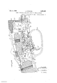
- Fig. 1 is a broken View partly in side elevation and partly in vertical longitudinal sec tion of the frame-portion ofa double-"barrel shotgun embodying my invention, together with the parts associated therewith and showing the parts in the positions due to them when both the firing-mechanisms are intheir cocked positions;
- Fig.2 is a view corresponding to Fig. 1,
- Fig. 3 is a corresponding View, but showing the parts in the positions due to them after the initial rearward draft upon the 5 trigger has been relaxed, and with the parts in the positions in readiness to release the left-hand firin -mechanism;
- Fig. is a broken view in horizontal section taken on the line -5 of Fig.1;
- Fig. 6 is a broken detail view looking downward upon the sear-actuator andthe rear ends of the respective sears;
- Fig. 7 is an enlarged-scale detachedmperspective View of the selective seareactuator
- Fig. 8 is a similar view of. the trigger. and the'trigger-blade organized therewith;
- Fig. 9 is a corresponding view of the man ually-operable selector-button.
- The.said-ha1n ners 28 and .-29:a1 e alsoformed at their lower .ends, adjacent. their searmotches,respectiverly; Wltl1.,(l21l1'lr1lk6,hl$ .32 and .38
- Thehaminers28.and.29,,jnstabovereferred ..to,.are.n1onnted upon a transverse pivotpm 34 mounted in-the frame 20, and are respectively formed with notches and 36 receiving pins 37 and 38 of hammeroperating" links '39 an d 40, in, the usual man nor of .fir'earm. construction; it being under stood'that the links '39 and 40 exert aconstant eifort upon their respective hammers 28' and 29 to swing the upper ends of the same "forward into their firingpositions.
- mer 28 coacts with the forward endof a v horizontally-arranged sear 41, mounted about midway of its length for oscillation upon a transverse pin 42 in the :frame 20.
- the 'blade' 'fi is located in an upwardly-opening longitudinal V W groove- 51 for-med in -a trigger52,ywhile the -selector button 49 is mounted? foraxial move ment 5 in a. direction transverse to theqna-j or be axis of'theguirin a bore 53-formed in the" f said trigger withinthe profile of the fingep-s piece thereof and intersectingtheygroovefill aforesaid.
- I -1 o x It will be seen from the foregoing that the -sear aetuator l 5 is-inountedupon the reduced.
- selectors-button 49 with capacity for swinging movement/"tier -ward-and back and that by virtue of the; F fact that 'its'rnotched lower :end'; is entered 0 into the annular groove 48 in the said, i: selector-button 49, "it :will. participate in :any inovementof the latter: in a direction cross- -w ise of thegun,as:will hereinafter appear,
- the arm 5'5 of the spring 5'6 plays-up and down in a vertical guide-slotGO extending between the bore 59 and the upwardly-opening longitudinal groove 51. of the said trigger, w; in which the'lower endof the blade lfi of't he A sear-actuatoris located.
- first-stage sear actuating ledge 44 of the sear-actuator which is curved, as shown, to conform to an arc swung about the center of the selectorebutton 49, as is also a right-hand second-stage searactuating ledge 62 which is located to the rear and to one side of the aforesaid firststage ledge 44, as clearly shown in Fig. 7 of the drawings, and forms the upper surface of a horizontal rib 62- laterally offsetting from the right-hand side of the searactuator 45.
- the opposite side of the sear-actuator is also formed with a left-hand second-stage sear-actuating ledge 63 forming the upper surface of a complementary rib 63e and is adapted to coact with the under-face of the inwardly-turned sear finger 64 forming a feature of the left-hand sear 65 which, like the right-hand sear 41 already referred to, is mountedfor oscillating movement upon the transverse pin 42 and has its forwardend .coacting with the sear-notch 33 of the left- I trigger-blade 69 through which the pivotlocated in the said bore 77 thereof.
- pin 66 already referred to passes, so that the said blade, to all intents and purposes, forms an integral part of the trigger 52.
- a plunger 71 To yieldingly hold the finger-piece'YO of the trigger 52 in its normal forward position, as shown in Fig. 1, 1 employa plunger 71, the rear end of which engages with the forward edge of the trigger-blade 69 under the urge of a helical spring 7 2 mounted in a rearwardly-opening pocket 7 3 formed in the iump 26 and in which the said plunger 71 is adapted to reciprocate.
- the rearand under-face of the rear end of the trigger-blade 69 is adapted to coact with a pivotal inertia-weight 7 4 as will hereinafter appear, which is mounted upon a transverse pivot- 7 5 in the trigger-plate 22 and is normally held in its rearward or retired position by a plunger 7 6 engaging the upper surface of the said trigger-plate adjacent the pivot-pin 75 and reciprocating in an inclined bore 7 7' in the said inertia-weight and urged outward by a helical spring 78 also
- the upper edge of the rear portion of the trigger-blade 69 is adapted to coact on occasion with the under-face of a reciprocating safety-rod 79 and also to enter a vertical longitudinal clearance-slot 80 formed therein, as will hereinafter appear.
- Thexforward end 81 of the said safety-rod is of cylindrical form and reciprocates in a longitudinal passage 82 formed in the lump 26.
- the safety-rod 7 9 abovereferred to is formed with a bifurcated dependingresetting finger 83 adapted to coact with a re-setting lug 84 upwardly-extending from the sear-actuator 45 and is pivotally secured at its rear end by means of a pivotpin 85 to a substantially-vertical safety-lever 86 mounted for oscillation forward and back upon a pin 87 extending transversely through the trigger-plate 22, near the rear end there of.
- the rear end of the inertia-weight74 is formed with a clearance-notch. 88 for the clearance of the lever 86, the upper end of which latter is entered into a downwardlyopening notch -89 formed in a safety-slide 90 sliding longitudinally upon the upper face of the tang 21 of the frame 20 in the usual manner of safety mechanisms.
- a detentspring 91 is carried bythe said slide and formed at its forward end with an upwardlyextending hump 92 adapted to enter either one of two detent-notches 93 or 94 to retain thesaid slide in either one of its-two positions.
- the finger-piece 70 of the trigger 5 2 is guarded in the usual manner by atriggerbow 100 mount-ed upon the under-face of the trigger-plate 22, as clearly shown in Figs. 1, 2 and 3 inclusive.
- a single trigger serve's'to successively fire both barrels, either in the order right-left or left-right and that the location of the manually-operable selector-member or button in the trigger itself not only makes for convenience but simplifies the construction and arrangement of the parts and secures a unique certainty of action.
- the selector-button 49 is mounted in the trigger 52 above the finger-contact portion thereof, so as not to be 3 afiected by nor interfere with the users finger when the trigger is being pulled, or when the finger is being inserted preparatory to firing the arm. Furthermore, the said selector-button, owing to its novel location above the finger-contact surfaces ofthe trigger, is operable for selecting the firing sequence solely by pressure exerted crosswise of the trigger and does not require any coincidental upward pressure which might inadvertently fire the arm. V
- a single-trigger mechanism for multiple-barrel firearms the combination with a pair of firing-mechanisms; of a trigger; and a manually-shiftable actuator-member carried by the said trigger with capacity for bodily movement crosswise with respect thereto and oscillatory movement forward and back in the plane thereof and engageable with portions of'the said firing-mechanisms for releasing the same in a selective sequence when the said trigger is actuated.
- a single-trigger mechanism for multiple-barrel firearms the combination with a pair of firing-mechanisms including the respective sears thereof; of a trigger; and a manually-shiftable sear-actuator carried by the said trigger with capacity for movement both crosswise and longitudinally with respect thereto and engageable with the said sears for moving the same to release the said firing-mechanisms in a selective sequence when the said trigger is actuated.
- a single-trigger mechanism for multiple-barrel firearms the combination with a pair offiring-mechanisms including the respective sears thereof; of a trigger; and a manually-shiftable sear-actuator carried by the said trigger with capacity for bodily movement crosswise with respect thereto and oscillatory movement forward and back in the plane thereof and engageable with said sears for moving the same to release the said firing-mechanisms in a selective sequence when the said trigger is actuated.
- a single-trigger mechanism for multiple-barrel firearms the combination with a pair of firing-mechanisms including the respective sears thereof; of a trigger; a manually-shiftable sear-actuator carried by the said trigger with capacity for movement both crosswise and longitudinally with respect thereto and engageable with the said sears for moving the same torelease the said firingmechanisms in a selective sequence when the said trigger is actuated; and a manually-operable reciprocating selector-button mounted in the said trigger with capacity for movement transversely'with respect thereto and operatively connected to the said sear-actuator for shifting the same.
- a'single-trigger mechanism for multiple-barrel firearms the combination with a pair of firing-mechanisms including the respective sears thereof; of a trigger; a man ually-shiftable sear-actuator carried by the said trigger with capacity for bodily movement crosswise with respect thereto. and oscillatory movement forward and back in the plane thereof and engageable with said sears for moving the same to release the said firingmechanisms in a selective sequence when the said trigger is actuated; and a manually operable reciprocating selector-button mounted in the said trigger with capacity for movement transversely with respect thereto and operatively connected to the said searactuator for shifting the same.
- a single-trigger mechanism for multiple-barrel firearms the, combination with a pair of firing-mechanisms including the re. spective sears thereof; of a trigger; a manually-shijftable sear-actuator carried by the said trigger with capacity for movement both transversely and longitudinallythereof, and provided with a first-stage sear-actuating portion located thereon in position to be brought into registration with either of the said sea-rs and out of registration with the complementary sear by a transverse movement, and provided also with a second-stage sear-a0tuating portion located thereon in position to be.
- a single-trigger mechanism for muh tiple-barrel firearms as defined in claim 7 and having in combination a recoil-operated member coacting with a portion of the said trigger to temporarily hold the same in its retracted position; whereby the seareactuator carried by the said trigger is prevented from moving under the urge ofthe said spring-means into position for operating the second sear until the recoil and counter-recoil of the firearm have expended their forces.
- a single-trigger mechanism for multiple-barrel firearms including the respective sears thereof; of a trigger; a manually-shiftable sear-actuator carried by the said trigger with capacityfor bodily movement transversely thereof and swinging movement longitudinally thereof and provided with a first-stage sear-actuating portion located thereon in position to be brought into registration witheither of the said sears and out of registration with the complementary sear by a transverse movement and provided also with a second-stage sear-aotuating portion located thereon in position to be brought into registration with the said complementary sear by a rocking movement in a; plane'longitudinal out the said trigger; and
- a single-trigger mechanism for-multiple-barrel firearms the combination with a pair of firing-mechanisms, including the respective sears thereof; of a trigger; a manually-operable selector-button mounted within the exposed profile of the trigger for transverse reciprocating movement therein; and a manually-shiftable sear-actuator member pivotally mounted for longitudinal rocking movement upon the said selector-button.
- a single-trigger mechanism for multiple-barrel firearms the combination with a pair of firing-mechanisms including the respective sears thereof; of a trigger; a manually-operable selector-button mounted within the exposed profile of the trigger for transverse reciprocating movement therein; and a manually-shiftable sear-actuator member pivotally mounted for longitudinal rocking movement upon the said selector-button and bodily movable transversely therewith.
- a single-trigger mechanism for multiple-barrel firearms the combination with a pair of firing-mechanisms including the respective sears thereof; of a trigger; a searactuator mounted in the firearm-structure with capacity for both transverse and longitudinal movement with respect thereto; and a spring operatively connected to the said sear-actuator for yieldingly maintaining the same at either limit of its transverse movement and for moving the same longitudinally with respect to the firearm-structure.
- a single-trigger mechanism for multiple-barrel firearms the combination with a pair of firing-mechanisms including the re spective sears thereof; of a trigger; a substitute-ctuator carried by the said trigger with capacity for both transverse and longitudinal movement with respect thereto; and a spring operatively connected to the said searactuator for yieldingly maintaining the same at either limit of its transverse movement and for moving the same longitudinally with respect to the said trigger.
- a single-trigger mechanism for multiple-barrel firearms the combination with a pair of firing-mechanisms including the respective sears thereof; of a trigger; a sear- V actuator mounted in the firearm-structure with capacity for both transverse and longitudinal movement with respect thereto; and torsion-spring operatively connected to the said sear-actuator for yieldingly maintaining the same at either limit ofrits transverse movement and for moving the same longitudinally with respect to the firearmstructure.
- a singletrigger mechanism for multiple-barrel firearms the combination with a pair of firing-mechanisms including the respective sears thereof; of a trigger; a manually-operable selector-button mounted in the said trigger with capacity for transverse reci arocating movement therein; a transversely-shiftable and longitudinally-movable searactuator carried by the said trigger and operatively connected to the said selector-button; and a spring operatively connected to the said sear-actuator for yieldingly maintaining the same at either limit of its transverse movement and for moving the same longitudinally with respect to the said trigger.
- a single-trigger mechanism for multiple-barrel firearms the combination with a pair of firing-mechanisms including the respective sears thereof; of a trigger; a searactuator carried by the said trigger with capacity for both transverse bodily movement and longitudinal oscillating movement with respect thereto; and a spring operatively connected to the said sear-actuator for yieldingly holding the same at either limit of its transverse movement and for rocking the same longitudinally with respect to the said trigger.
- a single-trigger mechanism for multiple-barrel firearms the combination with a pair of firing-mechanisms including the respective sears thereof; of a trigger; a searactuator carried by the said trigger with capacity for both transverse bodily movement and longitudinal oscillating movement with respect thereto; and a spring carried by the said trigger and operatively connected to the said sear-actuator for yieldingly holding the same at either limit of its transverse movement and for rocking the same longitudinally with respect to the said trigger,
Description
Dec. 6,1932, s N 1,890,005
SINGLE TRIGGER MECHANISM FOR MULTIPLE BARREL FIREARMS Original Filed July 24, 1930 4 Sheets-Sheet 1 AfTTO/PAAS'YJ 6, f- L. STIENNON 1,890,005
SINGLE TRIGGER MECHANISM FOR MULTIPLE BARREL FIREARMS Original Filed July 24, 1930 4 Sheets-Sheet 2 Dec. 0, 1032. T N 1,800,005
SINGLE TRIGGER MECHANISM FOR MULTIPLE BARREL FIREARMS Original Filed July 24, 1950 4 Sheets-Sheet s L. STZENNQN Dec. 0, 1932.
SINGLE TRIGGER MECHANISM FOR MULTIPLE BARREL FIREARMS 4 Sheets-Sheet 4 Original Filed July 24, 1930 LOUIS s'rzsn'non, or new equipped with uufailing attention of the Fatented Dec. 6, 1932 YET i Vii-N, serra ions-or, assienoa, BY truer-in asszeniannrs,
TO WINCHESTER REPEATING- ARIES CGItiPAHY, OF HAVEN, CONNECTICUT, A
CORPORATION OF IJIAEYLAK SINGLE-TREGGEB, MECHAIZESM FOR MULTIPLE-BARREL FIREARMS Continuation of-application Serial No. 470,412, filed 1931. Serial This application constitutes a continuation of application Serial No. l? 0,412, filed July 24, 1930, allowed August 3, 1981, and abandoned for the sole purpose of permitting the present application to be substituted therefor.
This invention relates to an improvement in trigger-mechanisms for multiple-barrel firearms and relates in particular to an improvement in that class of trigger-mechanisms in which a single trigger serves to release two or morefiring-mechanismsin selective sequence.
The main'object of this invention is to provide a simple, strong and compact triggermechanism of the type referred to, constructed with particular reference to safety and reliability and convenience of operation.
ilnotherobject of this invention is to provide a single-trigger mechanism of the type referred to, with simple, reliable and conveniently-located means for selecting the firin se .uence of the barrels so. that the user of the firearm can readily understand the op-' eration thereof. y
I am aware that it has heretofore beenproposed to mount a selector or control-member .for a single-trigger mechanismin the trigger of a firearm, but such previousimechanism, while theoretically advantageous, has been open to the serious objection that its manual operation required the exertion of pressure of such character upon the trigger itself as would cause the accidental discharge of the arm unless the user took the exceptional precaution of first throwin on the safety mech anism (if such were part of the gun mechanism), and subsequently, after having made the selection of firing order, remembering to throw the safety mechanism off. The result has been that a single-tigger firearm, such a selector mechanism, would have been very dangerous and could be rendered reasonably safe only by the user and the religious performance of the ritual of throwmg the safety mechanism into engagement before attemptingto reverse the firing seouence and then retiring the safety mechanism before the arm. Could become ava11- July 24, 1930. This application filed September 23,
ablefoir firing. Usually, a choice of firing order must be made at the instant of sightmg the'game and it goes without saying that if the user must first go through the complicated steps above outlined, the game would usually escape. r v
A further and important object of my invention, therefore, is to provide a singletrigger mechanism havinga-manual controlor selector-means with the advantages due to being mounted'upon the trigger itself, such convenience of operation, unmistakability of purpose and ease of ascertainment ofposi- -tion by sight or feeling, yet so located that it may be. operated Without endangeringthe premature discharge of the arm due to pressure in a direction normal to the firing movement of the trigger, or interfere with the free insertion of the finger for firing.
With the above and other objects in view as will appear fromthe following, my invention consists in a single-trigger mechanism for multiple-barrel firearms, having certain features of construction and arrangements of parts'as will be hereinafter described and particularly recited in the claims.
In the accompanying drawings:
Fig; 1 is a broken View partly in side elevation and partly in vertical longitudinal sec tion of the frame-portion ofa double-"barrel shotgun embodying my invention, together with the parts associated therewith and showing the parts in the positions due to them when both the firing-mechanisms are intheir cocked positions; Fig.2 is a view corresponding to Fig. 1,
but showing the parts in the positions due to them after the trigger hasbeen pulled and the right-hand firing-mechanism has been released, but before the rearward draft upon the trigger has been relaxed;
Fig. 3 is a corresponding View, but showing the parts in the positions due to them after the initial rearward draft upon the 5 trigger has been relaxed, and with the parts in the positions in readiness to release the left-hand firin -mechanism;
Fig. 4 is a transverse sectional View taken on the line :4= of Fig. 1;v
Fig. is a broken view in horizontal section taken on the line -5 of Fig.1;
Fig. 6 is a broken detail view looking downward upon the sear-actuator andthe rear ends of the respective sears;
Fig. 7 is an enlarged-scale detachedmperspective View of the selective seareactuator;
1 Fig. 8 is a similar view of. the trigger. and the'trigger-blade organized therewith; and
Fig. 9 is a corresponding view of the man ually-operable selector-button.
In the main figures of the accompanying dra-wings,l have illustrated: the firing meolr anisms and associated parts of a double barrel break-down'shotgun, though it will be :understood that my invention is applicable to "various types'o'f :multiple barrel firearms.
5 In the embodimentof my invention herein chosen for illustratiom- I employ ai'frame 2O 'formed at its upper' rear rend -:with :a a rearwardly-extending tang 21 andha-vingseoured -to its under ":face a trigger-191M922 between the-upper face of the rearend of which latter and the under face oft-he 'tang- 21, is se- 'cured theifenrward'endof butt stock 23. "A
relatively-dong screw 2sextends: upward 'between the "rear -end:o'f the trigger+plate 22 --aforesaid a-n'd thez-rear end ofst-he tang 21 I 0f the frame 20, and serves-to'ancho-r the buttstock 23 in place inrconjunction with a screw "25 extending downward throughthe forward end ofthe' tang 21- and. into: theupper end-of-a zso'called lum"'-26, "formed integral -with and upstandingi from the: trigger-plate 22 .alr-ready' referred? to. i
J .The butt-stock 23.:abovere-ferred to is cut iawayrto: clear: the mechanism about to be de- .iSCilliledlanClls provided near itsforward end -enTd of-.the-'fra1ne.2() are a; pair ofecorrespon'dvingham mere; 28. and, 2-9 respectively provided sat their forwardmpperaends .with firing-pins and 3.1, and in their lower; rear .walls with sear-notches 32 and 33. The.said-ha1n ners 28 and .-29:a1=e alsoformed at their lower .ends, adjacent. their searmotches,respectiverly; Wltl1.,(l21l1'lr1lk6,hl$ .32 and .38
Thehaminers28.and.29,,jnstabovereferred ..to,.are.n1onnted upon a transverse pivotpm 34, mounted in-the frame 20, and are respectively formed with notches and 36 receiving pins 37 and 38 of hammeroperating" links '39 an d 40, in, the usual man nor of .fir'earm. construction; it being under stood'that the links '39 and 40 exert aconstant eifort upon their respective hammers 28' and 29 to swing the upper ends of the same "forward into their firingpositions.
=The sear-notch: 32.01: the right-hand hamsaid annular groove 48.
mer 28.coacts with the forward endof a v horizontally-arranged sear 41, mounted about midway of its length for oscillation upon a transverse pin 42 in the :frame 20.
The rear end of' the right-hand sear 41 is .provided with an inwardly-projecting finger A3 adaptedto be liftedby what I shall, for
-,;4;6,II12.ITOW81 than the body-portion proper thereof, and formed in its lower end with age" downwardly-opening notch =47,- entering an 'LIII1 11l&l= g1-OOV6 =48 "formed -mi'dway -i-n--,a re- -ci=procating selector-button -4e9 -and embrae, -in-g:the reduced central porti0n50 of thevsaid V "butt-om're-sulting' from the i formation: of the? 35 The 'blade' 'fi is located in an upwardly-opening longitudinal V W groove- 51 for-med in -a trigger52,ywhile the -selector button 49 is mounted? foraxial move ment 5 in a. direction transverse to theqna-j or be axis of'theguirin a bore 53-formed in the" f said trigger withinthe profile of the fingep-s piece thereof and intersectingtheygroovefill aforesaid. I -1 o x It will be seen from the foregoing that the -sear aetuator l 5 is-inountedupon the reduced. c central; portion of the selectors-button 49 with capacity for swinging movement/"tier -ward-and back and that by virtue of the; F fact that 'its'rnotched lower :end'; is entered 0 into the annular groove 48 in the said, i: selector-button 49, "it :will. participate in :any inovementof the latter: in a direction cross- -w ise of thegun,as:will hereinafter appear,
To provide for normally exertingalcon-giob' -stant effort-toswing-theupper end ofthe sear-actuator-45#forward and to fyieldingly; hold thesame, together with thebutton 4 9, ,in-eitherofitstwo positions of lateral ad- 2 fjustment, as will hereinafter appear, I pro-'f i l0};: vide the'forwardedge of'the blade tfiithere-f of "with an upwardly-'facin lwedge-sha g p detent-nose '5-i-,:the opposite sloping faces which are alternately engaged by-thei-real -wardly-extending arm; of a. torsion-spring 35 -56,-which latter is: also=provided with a for -wardly extending arm 5? located in a .hori-, zontal groove 58 formed'in the trigger52 and intersecting a transverse bore 59' also a 7 --formed in thesaid trigger and inwhich the i coil-portion of the spring 561 is located. The arm 5'5 of the spring 5'6-plays-up and down in a vertical guide-slotGO extending between the bore 59 and the upwardly-opening longitudinal groove 51. of the said trigger, w; in which the'lower endof the blade lfi of't he A sear-actuatoris located. 1 I I As before pointed out,tl1e sear-finger 43., of the right-hand searel is adapted-to coact' with the upwardly-facing."first-stage sear actuating ledge 44 of the sear-actuator, which is curved, as shown, to conform to an arc swung about the center of the selectorebutton 49, as isalso a right-hand second-stage searactuating ledge 62 which is located to the rear and to one side of the aforesaid firststage ledge 44, as clearly shown in Fig. 7 of the drawings, and forms the upper surface of a horizontal rib 62- laterally offsetting from the right-hand side of the searactuator 45.
The opposite side of the sear-actuator is also formed with a left-hand second-stage sear-actuating ledge 63 forming the upper surface of a complementary rib 63e and is adapted to coact with the under-face of the inwardly-turned sear finger 64 forming a feature of the left-hand sear 65 which, like the right-hand sear 41 already referred to, is mountedfor oscillating movement upon the transverse pin 42 and has its forwardend .coacting with the sear-notch 33 of the left- I trigger-blade 69 through which the pivotlocated in the said bore 77 thereof.
To yieldingly hold the finger-piece'YO of the trigger 52 in its normal forward position, as shown in Fig. 1, 1 employa plunger 71, the rear end of which engages with the forward edge of the trigger-blade 69 under the urge of a helical spring 7 2 mounted in a rearwardly-opening pocket 7 3 formed in the iump 26 and in which the said plunger 71 is adapted to reciprocate.
The rearand under-face of the rear end of the trigger-blade 69 is adapted to coact with a pivotal inertia-weight 7 4 as will hereinafter appear, which is mounted upon a transverse pivot- 7 5 in the trigger-plate 22 and is normally held in its rearward or retired position by a plunger 7 6 engaging the upper surface of the said trigger-plate adjacent the pivot-pin 75 and reciprocating in an inclined bore 7 7' in the said inertia-weight and urged outward by a helical spring 78 also The upper edge of the rear portion of the trigger-blade 69 is adapted to coact on occasion with the under-face of a reciprocating safety-rod 79 and also to enter a vertical longitudinal clearance-slot 80 formed therein, as will hereinafter appear. Thexforward end 81 of the said safety-rod is of cylindrical form and reciprocates in a longitudinal passage 82 formed in the lump 26.
Intermediate its ends, the safety-rod 7 9 abovereferred to is formed with a bifurcated dependingresetting finger 83 adapted to coact with a re-setting lug 84 upwardly-extending from the sear-actuator 45 and is pivotally secured at its rear end by means of a pivotpin 85 to a substantially-vertical safety-lever 86 mounted for oscillation forward and back upon a pin 87 extending transversely through the trigger-plate 22, near the rear end there of.
The rear end of the inertia-weight74 is formed with a clearance-notch. 88 for the clearance of the lever 86, the upper end of which latter is entered into a downwardlyopening notch -89 formed in a safety-slide 90 sliding longitudinally upon the upper face of the tang 21 of the frame 20 in the usual manner of safety mechanisms. A detentspring 91 is carried bythe said slide and formed at its forward end with an upwardlyextending hump 92 adapted to enter either one of two detent-notches 93 or 94 to retain thesaid slide in either one of its-two positions. V g
V The forward end of the cylindrical portion 81 of the safety-rod 7 9 is adapted tobe engaged by the rear face of a locking-bolt 95 in the usual manner of breakdown-firearms. The operationand construction of lockingmechanisms is so Well understood in the art that it is believed that no further description is required other than to say that the said locking-bolt 95 is retracted in'the usual manner by a finger 96 depending from a head 97 mounted upon the lower end ofthe shank 98 of a laterally-swinging top-lever 99 which effects the unlocking of the piece for breakdown action in the usual manner of breakdown firearms. I
The finger-piece 70 of the trigger 5 2 is guarded in the usual manner by atriggerbow 100 mount-ed upon the under-face of the trigger-plate 22, as clearly shown in Figs. 1, 2 and 3 inclusive.
Let it be supposed that the user desires to fire the right barrel of the gun first, in which case the gun will be cocked and the parts will occupy the'positions in which they are shown in Figs. 1, 4, 5 and 6. r
By reference to the figures just abovereferred to, it will be seen that both hammersare in their cocked positions and that the selector-button 49 has been manually forced from left to right, and held in such righthand position by the engagement of the arm 55 of .the spring 56 with the left-hand slope of the detent-nose 54. This action brings the first-stage sear-actuating ledge 44 beneath the sear-finger 43 of the right-hand sear 41 and hence removes the said ledge from beneath the sear-finger 64 of the left-hand sear no I 65, though {it will be noted by reference-Ito -6 in'pa rticular that the left-hand secondstage sear-operating ledge 63 is in line with and -slightly below the left-hand sear fi nger Q thoi'igh to'the rear thereof, in readiness to be swung forwa'id hy-the arm of the spring 56, beneath the said linger after the right-hand sea-'rha's been actuated, as will be presently described. 1 a
"VVith the parts in the positions asjust described, af'r'e'arward draft upon the finger- 'p'iece 70 of thetrigg'er will cause the latter toswing upon its 'p'in66 and lift the searactuator 45, with the effect of engaging the with the'u'nc'ler faceof the sear-finger 43 of the right-hand sear iL-and thus swing the latter soas'to disengage' i'tsforward end from the sear-notch in the right hand hammer -28. Thefrighthand hai'nme'nwillthus be permitt-ed to swing forvvard inthe usual manner of fi'rearms to fire'the cartridge in' the-right hand barrel (not shown"). v
In 's-wingi'ng into "position to fire a car- 'tridge, the right-hand hammer 28 will act through its eam like heel 32 't'o clepressthe forwardend of the right-hand sear 41, thus lifting the finger thereof above the right- 'hand "rib 62 -so that thesear-actuator is tempora'rily prevented froin swinging forward farm will ca-use the pivotal inertia-weight 7 4 to-assume the position in which it is shown by broken lines in Fig.2, in which position its periphery is interposed beneath the rear end of the trigger-blade 69, 'th'us te1nporaril-y blocking the return of the trigger to itsnor- 5 'mal position until the rebound or counter-recoil of the gun takes place, at which time the 'said inertia-weight will be returned "by-'tl1e combined action of the co'unter-recoiland its spring 78 to the position indicated "by full lines.
g The action ofthe inertiaew'eig'ht just above described serves at this time 'to p'reven't'the forward-movement of the'trigger 52'into'position for actuating the 1eft-hand sear as an incident to the recoil of the armand 'the'refore 'forestalls an involuntary second rearwardinovement of the trigger and the consequent unintentlonal firing of the second barrel as a result of the counter-recoil.
' The -right hand ba'rrel'having been fired -manner of breakdown-firearms. r When the locking-bolt 95' is-retracted as theguln. V
When the user is ready to fire the gunfhe 1 is manualIy moves the safety-slide '90 forward,
thereby bringing the clearance-slot 80 of'the as .j'ust' a bove :described and the recoilfiaind counter-recoil having expended :th'eir :force, V
the user deliberately relaxes rearwardrdraft upon the finger-piece of the trigger 52 to permit the said finger-piece toswing for-ward under the urge offthe'trigger spring 72. This f forward or return movementof the trigger lowe'rs the sear-actuator 45sufliciently'to disi i engage the forward wall of. its left-hand rib 63from *the rear end of thel left-hand sear- I finger 64 and thus permit the said-searactua'tor to swing forward minder the urge of the arm '55 of the spring 56 to interp'ose the left hand second-stage sear-actuating led'ge '6'31 beneath the sear-finger fi l of the'left hand sear 65. v The parts will now occup .th
sitions in which they are shown :in Figh3-in1 readiness to release the left-hand hammer2 9 forfiring the-'Ieft-hand ba'rreI notshown);
The parts having assumed therpositionsinwhich they are shown in Fig. 3, a subsequent rearward draft uponthe finger-.piece 70of the trigger 52 will lift 'thesea r actuator 45 and cause its left-hand second-stage sear-actuating ledge to engage the underside of the left-handsear-finger flt and thus lift the same, with theeifect of rocking'theHeft-hand sear '65rto disengage its forward end from the'sear-notch 83 of the left-hand hammer '29, thereby effecting the firing of the ileft-hand barrel (not shown). The inertia-weight 7 1;
will operate in the same'manner under the action of the recoil and counter-recoil of the firearm, as previously described. When the user wishes to 're-load"the arm,
he will swing the top-lever 99 'laterally'ito're-- tract the locking-bolt 95, and break the piece, thus effecting the cockingof both of the hammers 38a nd 29,allin the just above described,-it will force the safetywe'll-known I rod 7 9 rearward, with the effect of causing] the re-setting-finger 63 thereof to" engagethe -re-setting:lug 84 of the sea-reactuatonthus:res
turning it to the positionin =Which;it. isshown in Fig. 1, and with the furthereifectof m0v'-'- 7 ing the safety-slide' rearward and:moving, the clearance slot 80 of the said safety-rod'out of registration with the that "the trigger safety-rod 79. into registration with therear endof thetrigger blade 69,s0 that the t rigit Q 'ger maybe'operated when-desired. r I
In the foregoing clescriptionof operation, I have described my improved trigger mechanism as set to release the hammers 28 and 29 in theorder right-left, butit will be seen that if the user of the arm chooses to reverse the-firing-order,'namely, to left- -,right, he has but to apply a lateral pressure trigger-bladeGQ, so cannot be swung for firing" upon the selector-button 49 to move the same, together with the sear-actuator 45, to the limit of its left-hand movement, in which position the first-stage sear-actuating ledge $4: of the said sear-actuator will be interposed beneath the left-hand sear-fin ger 64 and removed from beneath the right-hand searfinger 43. I Vith the parts thus set, when the first pull is exerted upon the finger-piece of the trigger 52, the left-hand hammer 29 will be released in the samemanner as that already described in connection with the release of the right-hand hammer, and upon the release of rearward draft upon the finger piece 70, the parts will automatically adjust themselves so that the right-hand secondstage sear-actuating ledge 62 will be beneath the right-hand sear-finger 4:3, preparatory to rocking the same for releasing the right-ban d hammer 28 when the second rearward draft is imposed upon the finger-piece 70 of the trigger.
From the foregoing it will be seen that a single trigger serve's'to successively fire both barrels, either in the order right-left or left-right and that the location of the manually-operable selector-member or button in the trigger itself not only makes for convenience but simplifies the construction and arrangement of the parts and secures a unique certainty of action.
t will be noted that the selector-button 49 is mounted in the trigger 52 above the finger-contact portion thereof, so as not to be 3 afiected by nor interfere with the users finger when the trigger is being pulled, or when the finger is being inserted preparatory to firing the arm. Furthermore, the said selector-button, owing to its novel location above the finger-contact surfaces ofthe trigger, is operable for selecting the firing sequence solely by pressure exerted crosswise of the trigger and does not require any coincidental upward pressure which might inadvertently fire the arm. V
This advantage of being operable solely by lateralpressure is due also in part to the fact that my improved selector-member 1s sufficiently longer than the width of the 1mmediately adjacent portions of the trigger in which it is mounted to be capable of being thrown fully into either its rightor lefthand position by lateral pressure applied to the appropriate normally proj ectmg endand that, as the said selector-member pro ects only on the side corresponding'with the bar.-
, rel which will be fired by the first pull of the trigger, it thus provides a convenient visual or tactual indicator ofthe firing order of the arm. 7
It will be understood by those skilled in the art that my invention may assume varied physical forms without departing from my inventive concept, and I, therefore, do not limit myself to the specific embodiment herein chosen for illustratiom-but only as indileasing the same in a selective sequence when the said trigger is actuated.
2. In a single-trigger mechanism for multiple-barrel firearms, the combination with a pair of firing-mechanisms; of a trigger; and a manually-shiftable actuator-member carried by the said trigger with capacity for bodily movement crosswise with respect thereto and oscillatory movement forward and back in the plane thereof and engageable with portions of'the said firing-mechanisms for releasing the same in a selective sequence when the said trigger is actuated. l
3. In a single-trigger mechanism for multiple-barrel firearms, the combination with a pair of firing-mechanisms including the respective sears thereof; of a trigger; and a manually-shiftable sear-actuator carried by the said trigger with capacity for movement both crosswise and longitudinally with respect thereto and engageable with the said sears for moving the same to release the said firing-mechanisms in a selective sequence when the said trigger is actuated. 4. In a single-trigger mechanism for multiple-barrel firearms, the combination with a pair offiring-mechanisms including the respective sears thereof; of a trigger; and a manually-shiftable sear-actuator carried by the said trigger with capacity for bodily movement crosswise with respect thereto and oscillatory movement forward and back in the plane thereof and engageable with said sears for moving the same to release the said firing-mechanisms in a selective sequence when the said trigger is actuated.
5. In a single-trigger mechanism for multiple-barrel firearms, the combination with a pair of firing-mechanisms including the respective sears thereof; of a trigger; a manually-shiftable sear-actuator carried by the said trigger with capacity for movement both crosswise and longitudinally with respect thereto and engageable with the said sears for moving the same torelease the said firingmechanisms in a selective sequence when the said trigger is actuated; and a manually-operable reciprocating selector-button mounted in the said trigger with capacity for movement transversely'with respect thereto and operatively connected to the said sear-actuator for shifting the same.
6. In a'single-trigger mechanism for multiple-barrel firearms, the combination with a pair of firing-mechanisms including the respective sears thereof; of a trigger; a man ually-shiftable sear-actuator carried by the said trigger with capacity for bodily movement crosswise with respect thereto. and oscillatory movement forward and back in the plane thereof and engageable with said sears for moving the same to release the said firingmechanisms in a selective sequence when the said trigger is actuated; and a manually operable reciprocating selector-button mounted in the said trigger with capacity for movement transversely with respect thereto and operatively connected to the said searactuator for shifting the same.
' 7. In a single-trigger mechanism for multiple-barrel firearms, the, combination with a pair of firing-mechanisms including the re. spective sears thereof; of a trigger; a manually-shijftable sear-actuator carried by the said trigger with capacity for movement both transversely and longitudinallythereof, and provided with a first-stage sear-actuating portion located thereon in position to be brought into registration with either of the said sea-rs and out of registration with the complementary sear by a transverse movement, and provided also with a second-stage sear-a0tuating portion located thereon in position to be. brought into registration with the said complementary sear by a movement in a plane longitudinal of the said trigger when the initial pull thereupon is relaxed; and spring-means normally urging the said sear-actuator longitudinally of the said trigger and in a direction to bring the said second-stage sear-actuating portion into registration with .the said complementary sear. 8. In a single-trigger mechanism for muh tiple-barrel firearms as defined in claim 7 and having in combination a recoil-operated member coacting with a portion of the said trigger to temporarily hold the same in its retracted position; whereby the seareactuator carried by the said trigger is prevented from moving under the urge ofthe said spring-means into position for operating the second sear until the recoil and counter-recoil of the firearm have expended their forces.
9. In a single-trigger mechanism for multiple-barrel firearms, the combination with a pair of firing-mechanisms including the respective sears thereof; of a trigger; a manually-shiftable sear-actuator carried by the said trigger with capacityfor bodily movement transversely thereof and swinging movement longitudinally thereof and provided with a first-stage sear-actuating portion located thereon in position to be brought into registration witheither of the said sears and out of registration with the complementary sear by a transverse movement and provided also with a second-stage sear-aotuating portion located thereon in position to be brought into registration with the said complementary sear by a rocking movement in a; plane'longitudinal out the said trigger; and
spring-means normally tending to swing the said sear-actuator longitudinally of the said trigger and in a direction to bring its second-' stage sear-actuating portion intoregistrationj with the said complementary sear. i I
10.,In a single trigger mechanism for I multiple-barrel firearms the combination with a pair of firing-mechanisms including the respective sears thereof; of a trigger; a manually-slnftable sea-nactuator carried by the said trigger with capacity for-movement both transversely and longitudinally there of, and provided with a first-stage sear-actue ating portion located thereon in position to? be brought into registration witliv 'either ofthesaid sears andoutof registration with the complementary sear by a transverse movement, and provided also with a second-stage sear-actuating portion located'thereon in position to be brought into registration with the said complementary sear by a movement in a plane longitudinal of the said trigger when the initial pull thereupon is relaxed; spring means normally urging the said sear-actuator longitudinally of the said trigger and in p a a direction to bring the said second-stage sear-actuating portion into registration with the said complementary sear; and a manually-operable selector mounted in the said trigger with capacity for movement transversely said trigger with capacity for bodily movemelnt transversely thereof and provided with a first-stage sear-actuating portion located thereon in'position to be brought into regis-T tration with either of the said sears and-out of registration with the complernentarysear by a transverse movement, and provided also with a second-stage sear-actuating portion 10- cated thereon in position to be brought into registration with the said complementary sear by a rocking movement in a plane lOngitudi nal of the said trigger; spring-means normal ly tending to swingthe said'sear actuator longitudinally ofthe said trigger and'in a direction to bring its second-stage sear-acti ab' i119; portion into registration with the'said complementary-sear; and a manually-open able reciprocating selector-button mounted;
in the said trigger with capacityfor movev, ment transversely with respect thereto and operatively connected to the saidsear-actua-a tor for shifting the'sametransversel-y of said trigger. V
12. In a single-trigger mechanism for-multiple-barrel firearms; the combination witha pair of firing-mechanisms, including the respective sears thereof; of a trigger; a manually-operable selector-button mounted within the exposed profile of the trigger for transverse reciprocating movement therein; and a manually-shiftable sear-actuator member pivotally mounted for longitudinal rocking movement upon the said selector-button.
13. In a single-trigger mechanism for multiple-barrel firearms, the combination with a pair of firing-mechanisms including the respective sears thereof; of a trigger; a manually-operable selector-button mounted within the exposed profile of the trigger for transverse reciprocating movement therein; and a manually-shiftable sear-actuator member pivotally mounted for longitudinal rocking movement upon the said selector-button and bodily movable transversely therewith.
l l. In a single-trigger mechanism for multiple-barrel firearms, the combination with a pair of firing-mechanisms including the respective sears thereof; of a trigger; a searactuator mounted in the firearm-structure with capacity for both transverse and longitudinal movement with respect thereto; and a spring operatively connected to the said sear-actuator for yieldingly maintaining the same at either limit of its transverse movement and for moving the same longitudinally with respect to the firearm-structure.
15. In a single-trigger mechanism for multiple-barrel firearms, the combination with a pair of firing-mechanisms including the re spective sears thereof; of a trigger; a seara-ctuator carried by the said trigger with capacity for both transverse and longitudinal movement with respect thereto; and a spring operatively connected to the said searactuator for yieldingly maintaining the same at either limit of its transverse movement and for moving the same longitudinally with respect to the said trigger.
16. In a single-trigger mechanism for multiple-barrel firearms, the combination with a pair of firing-mechanisms including the respective sears thereof; of a trigger; a sear- V actuator mounted in the firearm-structure with capacity for both transverse and longitudinal movement with respect thereto; and torsion-spring operatively connected to the said sear-actuator for yieldingly maintaining the same at either limit ofrits transverse movement and for moving the same longitudinally with respect to the firearmstructure.
1'4' In a singletrigger mechanism for multiple-barrel firearms the combination with a pair of firing-mechanisms including the respective sears thereof; of a trigger; a manually-operable selector-button mounted in the said trigger with capacity for transverse reci arocating movement therein; a transversely-shiftable and longitudinally-movable searactuator carried by the said trigger and operatively connected to the said selector-button; and a spring operatively connected to the said sear-actuator for yieldingly maintaining the same at either limit of its transverse movement and for moving the same longitudinally with respect to the said trigger.
18. In a single-trigger mechanism for multiple-barrel firearms, the combination with a pair of firing-mechanisms including the respective sears thereof; of a trigger; a searactuator carried by the said trigger with capacity for both transverse bodily movement and longitudinal oscillating movement with respect thereto; and a spring operatively connected to the said sear-actuator for yieldingly holding the same at either limit of its transverse movement and for rocking the same longitudinally with respect to the said trigger.
19. In a single-trigger mechanism for multiple-barrel firearms, the combination with a pair of firing-mechanisms including the respective sears thereof; of a trigger; a searactuator carried by the said trigger with capacity for both transverse bodily movement and longitudinal oscillating movement with respect thereto; and a spring carried by the said trigger and operatively connected to the said sear-actuator for yieldingly holding the same at either limit of its transverse movement and for rocking the same longitudinally with respect to the said trigger,
In testimony whereof, I have signed this specification.
LOUIS STIENNON.
Priority Applications (1)
| Application Number | Priority Date | Filing Date | Title |
|---|---|---|---|
| US565535A US1890005A (en) | 1931-09-23 | 1931-09-23 | Single-trigger mechanism for multiple-barrel firearms |
Applications Claiming Priority (1)
| Application Number | Priority Date | Filing Date | Title |
|---|---|---|---|
| US565535A US1890005A (en) | 1931-09-23 | 1931-09-23 | Single-trigger mechanism for multiple-barrel firearms |
Publications (1)
| Publication Number | Publication Date |
|---|---|
| US1890005A true US1890005A (en) | 1932-12-06 |
Family
ID=24259049
Family Applications (1)
| Application Number | Title | Priority Date | Filing Date |
|---|---|---|---|
| US565535A Expired - Lifetime US1890005A (en) | 1931-09-23 | 1931-09-23 | Single-trigger mechanism for multiple-barrel firearms |
Country Status (1)
| Country | Link |
|---|---|
| US (1) | US1890005A (en) |
Cited By (7)
| Publication number | Priority date | Publication date | Assignee | Title |
|---|---|---|---|---|
| US3786588A (en) * | 1971-08-13 | 1974-01-22 | Franchi Spa Luigi | Arrangement for pre-selecting the sequence of firing of a double-barrelled gun having a single trigger |
| US20040128897A1 (en) * | 2001-04-11 | 2004-07-08 | Sergej Popikow | Lock system for multibarrel guns |
| US8671605B2 (en) | 2012-08-17 | 2014-03-18 | Bruce K. Siddle | Off-trigger locator |
| US8782937B2 (en) | 2012-08-17 | 2014-07-22 | David A. Grossman | Safety index for a firearm |
| USD755326S1 (en) | 2014-09-02 | 2016-05-03 | Bruce K. Siddle | Firearm with off-trigger locator |
| USD755327S1 (en) | 2014-09-02 | 2016-05-03 | Bruce K. Siddle | Off-trigger locator attachment |
| USD767075S1 (en) | 2015-02-19 | 2016-09-20 | David A. Grossman | Ergonomic grip for a slide of semiautomatic firearm |
-
1931
- 1931-09-23 US US565535A patent/US1890005A/en not_active Expired - Lifetime
Cited By (8)
| Publication number | Priority date | Publication date | Assignee | Title |
|---|---|---|---|---|
| US3786588A (en) * | 1971-08-13 | 1974-01-22 | Franchi Spa Luigi | Arrangement for pre-selecting the sequence of firing of a double-barrelled gun having a single trigger |
| US20040128897A1 (en) * | 2001-04-11 | 2004-07-08 | Sergej Popikow | Lock system for multibarrel guns |
| US6796067B2 (en) * | 2001-04-11 | 2004-09-28 | S.A.T. Swiss Arms Technology Ag | Lock system for multibarrel guns |
| US8671605B2 (en) | 2012-08-17 | 2014-03-18 | Bruce K. Siddle | Off-trigger locator |
| US8782937B2 (en) | 2012-08-17 | 2014-07-22 | David A. Grossman | Safety index for a firearm |
| USD755326S1 (en) | 2014-09-02 | 2016-05-03 | Bruce K. Siddle | Firearm with off-trigger locator |
| USD755327S1 (en) | 2014-09-02 | 2016-05-03 | Bruce K. Siddle | Off-trigger locator attachment |
| USD767075S1 (en) | 2015-02-19 | 2016-09-20 | David A. Grossman | Ergonomic grip for a slide of semiautomatic firearm |
Similar Documents
| Publication | Publication Date | Title |
|---|---|---|
| US1391499A (en) | Firearm | |
| US2675638A (en) | Fire control for firearms | |
| US2383487A (en) | Automatic gun | |
| US1890005A (en) | Single-trigger mechanism for multiple-barrel firearms | |
| US3996686A (en) | Gear-driven double-action firing mechanism for firearms | |
| US3029708A (en) | Trigger mechanism for automatic firearms | |
| US1661949A (en) | Interchangeable rifle and shotgun barrel | |
| US2711042A (en) | Single trigger mechanism for double barrel guns | |
| US361100A (en) | Lock device for fire-arms | |
| US2533283A (en) | Trigger mechanism | |
| US2052957A (en) | Single trigger mechanism | |
| US2341033A (en) | Firearm | |
| US2388149A (en) | Sear for firearms | |
| US3616725A (en) | Repeating firearm actions | |
| US1459108A (en) | Firearm | |
| US756039A (en) | Breech-loading firearm. | |
| US2230372A (en) | Trigger and sear mechanism for firearms | |
| US1902702A (en) | Shotgun | |
| US2251174A (en) | Sear mechanism | |
| US2336188A (en) | Single trigger mechanism for double barrel guns | |
| US1578639A (en) | Firearm | |
| US753414A (en) | Mldvoi | |
| US2268349A (en) | Selective single trigger | |
| US2142000A (en) | Single trigger mechanism for double-barreled guns | |
| US1898000A (en) | Trigger mechanism |