US1859972A - Safety pipe fitting - Google Patents
Safety pipe fitting Download PDFInfo
- Publication number
- US1859972A US1859972A US510417A US51041731A US1859972A US 1859972 A US1859972 A US 1859972A US 510417 A US510417 A US 510417A US 51041731 A US51041731 A US 51041731A US 1859972 A US1859972 A US 1859972A
- Authority
- US
- United States
- Prior art keywords
- pipe
- members
- cap
- opening
- fitting
- Prior art date
- Legal status (The legal status is an assumption and is not a legal conclusion. Google has not performed a legal analysis and makes no representation as to the accuracy of the status listed.)
- Expired - Lifetime
Links
Images

Classifications
-
- F—MECHANICAL ENGINEERING; LIGHTING; HEATING; WEAPONS; BLASTING
- F16—ENGINEERING ELEMENTS AND UNITS; GENERAL MEASURES FOR PRODUCING AND MAINTAINING EFFECTIVE FUNCTIONING OF MACHINES OR INSTALLATIONS; THERMAL INSULATION IN GENERAL
- F16L—PIPES; JOINTS OR FITTINGS FOR PIPES; SUPPORTS FOR PIPES, CABLES OR PROTECTIVE TUBING; MEANS FOR THERMAL INSULATION IN GENERAL
- F16L45/00—Pipe units with cleaning aperture and closure therefor
-
- F—MECHANICAL ENGINEERING; LIGHTING; HEATING; WEAPONS; BLASTING
- F16—ENGINEERING ELEMENTS AND UNITS; GENERAL MEASURES FOR PRODUCING AND MAINTAINING EFFECTIVE FUNCTIONING OF MACHINES OR INSTALLATIONS; THERMAL INSULATION IN GENERAL
- F16L—PIPES; JOINTS OR FITTINGS FOR PIPES; SUPPORTS FOR PIPES, CABLES OR PROTECTIVE TUBING; MEANS FOR THERMAL INSULATION IN GENERAL
- F16L41/00—Branching pipes; Joining pipes to walls
- F16L41/02—Branch units, e.g. made in one piece, welded, riveted
Description
May 24, v -F, E KEY 1,859,972
SAFETY PIPE FITTING FledJan. 22, 1931 2 Sheets-Sheet l rrx 24, 1932. F, E, KEY 1,859,972
' SAFETY PIPE FITTING Filed Jan. '22, 1951- z sneefs-sheet 2 fa. 7 y f7@ 5 /fw/f/w'o/P /ZJfcw/a/r /ffy Patented May 24, 1932 UNITED STATES PATENT OF F ICE l FREDERICK E. KEY, OF ST. LOUIS, MISSOURI, .ASSIGN'OB TO KEY BOILER QUIPVIIEN'T COMPANY, OF EAST ST. LOUIS, ILLINOIS, A. CORPORATION F MISSOURI SAFETY PIPE FITTING Application mea Januaryaa, 1931. serial No. 510,417.
My invention relates to improvements in safety pipe fittings, and has for its primary object pipe fittings which are designed to be used on high pressure lines of any type.
A further object is to construct a pipe fitting which is provided` with an additional pipe retaining means so that there will be no danger of the pipe when becoming loosened in the fitting through any cause whatsoever from blowing out of the fitting and causing considerable damage.
Heretofore in the use of pipe fittings for oil stills and similar pipe lines used to convey highly heated gases ,or liquids, it frequently happened'that the pipe fitting and self as to leave an opening or tell-tale at the end of the fitting. By this construction any loosening of the pipe in the fitting can be readily discovered and remedied before any serious damage occurs. i
In the drawings,
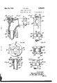
Fig. 1 is a side elevation of an L with parts broken away and in section, showing my improved construction;
Fig. 2 is an and View of the same;
Fig. 3 is a section taken on the of Fig. 1;
Fig. 4 is a top plan View of my improvement as attached to a flange coupling;
Fig. 5 is a vertical section taken on the line 5 5 of Fig. 4;
Fig'. 6 is a side elevation of Fig. 4; g
Fig. 7 is a horizontal section of my improvement when applied to a pipe coupling;
Fig. 8 is an end view of the same;
Fig. 9 is a longitudinal section of my device as applied to a T;
Fig. 10 is a section taken on the line 10-10 of Fig. 9;
Fig. 11 is a top plan view of the cap employed; and
line 3-3 Fig. 12 is a topplan view ofthe nut 'made use of in securing the cap in position.
In the construction of my device I employ a body portion 13 which vis made of any desired shape, in Fig. l, this shape being 'an L or one-fourth of a circle, so that thedevice can be used as an elbow or a corner fitting.
The ends 14ofthe fitting are bored'so as to provide a shoulder 15, adjacent which'is a tapered portion 17 which terminates infan annular groove 18, and adjacent the annular groove 18 is a taperedfportion 19. This style of boring or arranging the openings in the ends 14 is to permit the end of a pipe to be rolled and tightly seated in the fitting-by means of a tube expander. This tube expander is inserted through 'a cap opening 20 formed in the L, theopeningb'eing so varranged that access can-behadto either of the ends 14. g
The opening 20 'is'taperedand `is designed to yreceive a cap 21, which cap is securedin position by meansofl a set screw "or similar fastening Vmeans 22. The set screw 22 Vpasses through a nut 23 which nutis provided with extensions or arms-'24, these arms passing through slots 25 (see Figs. 7 to 10, inclusive) which are formed in the lugs-26. These lugs are located to either side of the opening 20 and are diametrically vopposite each other.
Located at a distance from each of the ends 14 is the auxiliary securing means which consists of a pair of spaced apart members 27 and 28. These members -are united to the body portion -13 by flexible ribs 29. These ribs extend only partially around the pipe, thus leaving an open space 30 which may be termed a telltale. The members 27 and 28 are provided 'with openings 31 through which bolts 32 pass. These'bolts are for the purpose ot'` drawing the sections 28 and 27 together so-as to tightly encircle the pipe.
It will be noted from Fig. 1 that when the pipe is rolled in its seat a 'bulge 38 is formed inthe pipe betweenthe members 27 and 28 andthe end 14 of the body-portion 13. This bulging or swelling prevents the pi e from being-blown outof lthefitting'in't e tol receive a cap similar to the cap 21.
event the end of the pipe 34 becomes looscned.
In Fig. 4 I have shown a modified form of construction in which a flange 35 is provided. This fiange has bolt openings 36 formed therein by means of which it can be attached to a similar flange. The flange 35 is provided with a boss 37, which boss may either be screw threaded as at 38 for the reception of the screw threaded end of a pipe 39, or it may be 'arranged similar to the opening or seat in the ends 14 of the body portion 13.
A pair of clamping members 40 and 41 are located at some distance beyond the end of the boss 37 and are connected to the boss by ribs 42. lThese ribs arc spaced apart so as to leave the telltale 43. The members 40 and 41 are provided with openings 44 for the reception of bolts 45. these bolts being for the same purpose as the bolts32. The pipe 39 is also provided withl a bulged portion 46 which extends around the pipe and is located within the space between the members 40 and 41 and the end of the boss 37.
In Figs. 7 and 8 I have shown another form of construction commonly called a coupling. This coupling consists of a pair of members 47 and 48 which are joined together by meansof a. web 49. The members 47 and 48 are hollow, as indicated by the numeral 50, and these hollow portions are joined together by a cross-passage 51. One end of the member 47 is provided with a screw threaded opening or pipe seat 52, adjacent which are the clamping members 53 and 54. These members are spaced apart and are designed to be drawn together' by means of bolts 55. l
Opposite the screw threaded opening 52 is a tapered opening 56 which is designed to The cap so used is not illustrated in this Figure, as it is fully shown in Fig. 1.
A pair of lugs 57 are located on oppoiste l sides of the opening 56 and are provided with slots 58 to receive the arms 24 of the nuts 23. The member 48 is provided with a screw threaded opening 59 and with split clamp members (i0 and 61. These members are connected to the member 48 by a web 62 so arranged as to leave a tell-tale G3.
Opposite the opening 59 is a tapered open ing 64 which also receives a cap. The member 48 is also provided with oppositely disposed lugs 65, which have the openings 25 therethrough' to receive the arms 24 of the nut 23.
The clamp members and 61 are drawn Y together b vmeans ot bolts 6G. In Figs. 9
and l() I have illustrated a T which is composed of members 67 and (38. These members have passages 69 formed therethrough, one end of which passage 69 is screw threaded as at 70. Opposite the screw threaded openings 70 are. the tapered openings 71, which receive caps 23. Lugs 72 are provided on opposite sides of the openings 7l for receiving the set screws which secure the caps in position. Adjacent the screw threaded ends 70 are split clamping members 73 and 74, which clamping members are drawn together by means of bolts, as previously described. The passages G9 are connected together by means of a web 75 through'which a passage 76 is formed so that communication may oe had between the adjacent passages G9. The web 75 has formed on one side a boss 77, through which a screw threaded opening 78 ext-ends. This opening communicates with the passage 76.
Adjacent the screw threaded opening 78 are formed clamping members 79 and 80. These members are. also split and are connected by the boss 77 by means of spacedapart ribs 8l, these ribs being arranged to form the tell-tale 82. The clamping members 79 and 80 are drawn together by means olf bolts 83. Directly opposite the opening 78 is a tapered opening 84which is also designed to receive a cap. This opening 84 is formed through the web 77 and boss 85. The boss 85 is `)rovided with slotted exten` sions 86 for hol ing the nut through which the set screw to secure the cap in position passes. It will be noted from my construetion that I have provided a pipe fitting which may be made in any desired form, which contains a safety collar or clamp so that in the event of the end of a pipe secured in the titting becoming loosened it will be impossible for the pipe to blow out. I have' discovered that when hot gases or fluids are handled by a pipe line, the pipe due to its thinner walls becomes heated more rapidly than the fitting. This causes the pipe to expand in the fitting, thus having a tendency to compress the molecules contained in the structure of the pipe. Then upon the cooling, the pipe being of thinneraconstruction, cools more readily and becomes loosened. Then when the pipe line is aga-in placed in operation, a certain amount lVhere the 'pipe line is used for conveying super-heated gases instead of solids lodged around th(` outside of the pipe where it is secured in the itting. these gases will lodge, and especially in the case ot super-heated steam, will have a tendency to cori-ode and lill? rust, thus again having a tendency to loosen the pipe within the fitting. I
While I have illustrated Fig. 1 as having i what may be termed a smooth bore fitting and the remainder of the fittings disclosing screw tlreads, it is to beunderstood that either kind around a pipe whose end is secured in said seat.
2. A safety pipe fitting comprising a hollow body fportion having aligned openings therein, a cap for closing one of said openings, means for securing said cap in said opening, a pipe seat formed in the opposing opening, clamping members integral with said body portion in alignment with and spaced' longitudinally from said pipe seat, and means for drawing said clamping members into close Contact with a pipe secured in said seat.
3. A safety pipe iitting comprising a hollow body portion, a pipe seat formed in said body portion and communicating with said hollow portion, integral flexible diametrically opposite ribs extending outwardly from said body portion, clamping members carried by said ribs in longitudinally spaced axial alignment to said tube seat so as to provide tell-tale openings, and means for drawing said clamping members toward each other and clamping the same around a pipe secured in and projecting from said seat.
4. A safety pipe fitting comprising a hollow body portion having aligned openings therein. a cap for closing one of said openings, means for securing said cap in said opening, a pipe seat formed in the opposing opening and adapted to have a pipe secured therein, clamp ing members carried by said body portion in alignment with and spaced away from said pipe seat, means for drawing said clamping members into close Contact with said pipe, slotted lugs projecting from said body portion adjacent said cap opening, and removable means carried by said lugs for securing said cap in position.
. 5. A pipe fitting comprising a pair of hollow members, a web connecting said members,
a passageway formed in said web and commufnicating with the interior of said members,
a pipe seat formed in each of said members, clamping members carried by and spaced longitudinally of said iirst mentioned members adjacent and concentric with said pipe seats, said members being so positioned as to leave tell-tale openings adjacent said pipe seats and adapted to be clamped about a pipe secured in each of said seats, a cap seat formed in each of said hollow members, and a cap removably secured in each of said cap seats.
6. A pipe ttin comprising a pair of hollow members, a we connecting said members, a passageway formed in said web and communicating with the interior of said members, a pipe seat formed in each of said members and adapted to have a pipe secured therein, clamping members carried b said rst mentioned members adjacent sai pipe seats, said members being so positioned as to leave telltale openings adjacent said pipe seats whereby leakage between said pipes and seats can be discovered/1lJ cap seat formed in each of said hollow members, a cap removably secured in each of said cap seats, and means for removably securing said caps in said cap seats.
In testimony whereof, I have hereunto afyfixed my hand this 19th da of January, A. D.
1931, in the' city of East t. Louis, county of St. Clair and State of Illinois.
FREDERICK E. KEY.
Priority Applications (1)
| Application Number | Priority Date | Filing Date | Title |
|---|---|---|---|
| US510417A US1859972A (en) | 1931-01-22 | 1931-01-22 | Safety pipe fitting |
Applications Claiming Priority (1)
| Application Number | Priority Date | Filing Date | Title |
|---|---|---|---|
| US510417A US1859972A (en) | 1931-01-22 | 1931-01-22 | Safety pipe fitting |
Publications (1)
| Publication Number | Publication Date |
|---|---|
| US1859972A true US1859972A (en) | 1932-05-24 |
Family
ID=24030650
Family Applications (1)
| Application Number | Title | Priority Date | Filing Date |
|---|---|---|---|
| US510417A Expired - Lifetime US1859972A (en) | 1931-01-22 | 1931-01-22 | Safety pipe fitting |
Country Status (1)
| Country | Link |
|---|---|
| US (1) | US1859972A (en) |
Cited By (4)
| Publication number | Priority date | Publication date | Assignee | Title |
|---|---|---|---|---|
| US4089101A (en) * | 1973-11-14 | 1978-05-16 | Balon Albert J | Method of forming a fluid seal between a tube and fitting |
| US6247869B1 (en) * | 1997-11-05 | 2001-06-19 | Ultra Lite Products, Inc. | Tubing connector |
| US9638365B1 (en) * | 2013-07-05 | 2017-05-02 | Marc Reviel | Multipurpose connector system |
| EP4058215A4 (en) * | 2019-11-15 | 2023-12-13 | Quest Integrity Group, LLC | Liquid intake with removable cover |
-
1931
- 1931-01-22 US US510417A patent/US1859972A/en not_active Expired - Lifetime
Cited By (4)
| Publication number | Priority date | Publication date | Assignee | Title |
|---|---|---|---|---|
| US4089101A (en) * | 1973-11-14 | 1978-05-16 | Balon Albert J | Method of forming a fluid seal between a tube and fitting |
| US6247869B1 (en) * | 1997-11-05 | 2001-06-19 | Ultra Lite Products, Inc. | Tubing connector |
| US9638365B1 (en) * | 2013-07-05 | 2017-05-02 | Marc Reviel | Multipurpose connector system |
| EP4058215A4 (en) * | 2019-11-15 | 2023-12-13 | Quest Integrity Group, LLC | Liquid intake with removable cover |
Similar Documents
| Publication | Publication Date | Title |
|---|---|---|
| US2021745A (en) | Threaded follower pipe joint or fitting | |
| US1802766A (en) | Pipe or tube joint | |
| US1890011A (en) | Coupling device | |
| US2399275A (en) | Fitting for flared tubing | |
| US3079992A (en) | Heat exchanger closure construction | |
| US1859972A (en) | Safety pipe fitting | |
| US2545789A (en) | Insertable strainer | |
| US1825034A (en) | Sectional pipe coupling | |
| US1935425A (en) | Pipe fitting | |
| US1797636A (en) | Pipe-coil header | |
| US1803577A (en) | Sectional pipe coupling | |
| US2125972A (en) | Heat exchanger | |
| US2358814A (en) | Tube connecting device | |
| US1852279A (en) | Means for securing tubes to headers | |
| US2117111A (en) | Tank flanged pipe coupling | |
| US1805321A (en) | Pipe coupling or connection | |
| US2555262A (en) | Plug valve | |
| US2269092A (en) | Container | |
| US1871810A (en) | Faucet connecter for fire hose | |
| US2148863A (en) | Return bend | |
| US2677557A (en) | Repair fitting for soft metal threaded connections | |
| US1675173A (en) | Header or coupling | |
| US2046029A (en) | Return bend for oil stills and the like | |
| US2182749A (en) | Liquid level gauge | |
| US1767677A (en) | Return bend fitting |