US1859968A - Art of refining hydrocarbons - Google Patents
Art of refining hydrocarbons Download PDFInfo
- Publication number
- US1859968A US1859968A US359451A US35945129A US1859968A US 1859968 A US1859968 A US 1859968A US 359451 A US359451 A US 359451A US 35945129 A US35945129 A US 35945129A US 1859968 A US1859968 A US 1859968A
- Authority
- US
- United States
- Prior art keywords
- oil
- heating
- heating element
- connection
- cracking
- Prior art date
- Legal status (The legal status is an assumption and is not a legal conclusion. Google has not performed a legal analysis and makes no representation as to the accuracy of the status listed.)
- Expired - Lifetime
Links
Images
Classifications
-
- C—CHEMISTRY; METALLURGY
- C10—PETROLEUM, GAS OR COKE INDUSTRIES; TECHNICAL GASES CONTAINING CARBON MONOXIDE; FUELS; LUBRICANTS; PEAT
- C10G—CRACKING HYDROCARBON OILS; PRODUCTION OF LIQUID HYDROCARBON MIXTURES, e.g. BY DESTRUCTIVE HYDROGENATION, OLIGOMERISATION, POLYMERISATION; RECOVERY OF HYDROCARBON OILS FROM OIL-SHALE, OIL-SAND, OR GASES; REFINING MIXTURES MAINLY CONSISTING OF HYDROCARBONS; REFORMING OF NAPHTHA; MINERAL WAXES
- C10G9/00—Thermal non-catalytic cracking, in the absence of hydrogen, of hydrocarbon oils
- C10G9/06—Thermal non-catalytic cracking, in the absence of hydrogen, of hydrocarbon oils by pressure distillation
-
- C—CHEMISTRY; METALLURGY
- C10—PETROLEUM, GAS OR COKE INDUSTRIES; TECHNICAL GASES CONTAINING CARBON MONOXIDE; FUELS; LUBRICANTS; PEAT
- C10G—CRACKING HYDROCARBON OILS; PRODUCTION OF LIQUID HYDROCARBON MIXTURES, e.g. BY DESTRUCTIVE HYDROGENATION, OLIGOMERISATION, POLYMERISATION; RECOVERY OF HYDROCARBON OILS FROM OIL-SHALE, OIL-SAND, OR GASES; REFINING MIXTURES MAINLY CONSISTING OF HYDROCARBONS; REFORMING OF NAPHTHA; MINERAL WAXES
- C10G7/00—Distillation of hydrocarbon oils
Definitions
- Thiszinvention provides avsimplilied oper,-
- an'A auxiliary Asupply of reflux condensate roInthe-refluxing operation is advantageously pefrvmfittd.
- A are;illportantadvanL ⁇ tageslof the invention.
- f j p The inventi n Will befurtherf described 1n l,connection yWith the accompanying
- a drawings which illustrate, ldiagrammatically and ⁇ :tormofla'pparatus for this purpose@V i 0 f. conventionally, c Velevation 4and partlyin section Aand with parts brokenfaway, neforin 4of,apparatus,adapted,forusein carryingif'out” v the processof the invention.
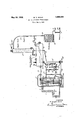
- the heating furnaceil comprises a fire-boxv 8 communicatingthrough a heating'lue'), 1 :'Withja stack'flue 10.
- the heating element'gQt ' is' arranged between .the upper" endo-fthe t heatingflue V9 and the freboxA 8so that 'the l,2 j QV heating gases pass first over it vvhile atjinaX- imum temperature.V
- the heating element@ i iS arranged ill fhefhetirls 111169750 that the lheating gases passover itatter ,passing ⁇ over y the heating'-V element 2 while atlovver'temf perature-.f 'lhey heating element Qmay com- 1 prise, for example,fforty 2f.
- Reflux' con-den- V satc'aor an oil mixture including reflux condensate issupp'lied from leg 15 through connections 21,22 and 23k by means of pump 24 tothe heating', element 2.
- connectionVv 29 is provided for discharging residu-al lunv'apor'- ized oil from the .drumvr 4V during n' operation.
- a series of level gauges 30 are rovided for determining the liquid iev-e1', i any@ the.
- the systemV may be' operatedV under a. pressure infthe ⁇ 'neiglfifborho'odr of ;150 pounds per square*infch,a:-orvv higher or lower pressures may bei1sed.
- higher pressures are advantageousin running lower boili'n-gcharging stocksfand lower pres sures may bey used-.in running higher boiling
- Raw oil maybezsupplied throughv connection V27' or through connection 28 or through both of these connections.:
- Raw oil may vlte'gsupe- 100 plied through connection 27" ⁇ for example,- at
- vapors inthereiux-toweri) ⁇ may/be v otherwise cooled tor condensatiouofhigher 3,15
- the retluxtowerjbe/iiig the same during' normal operation, Yexcept S5125 required toA maintain'circulation through cnn- VvI'iec'tiions 26,V 135,114, and 16,: the .actionfot :the "jet pipesf12 is alequaI tornaintainicircula- Y tion ⁇ 'thr-"ojugh4 the ⁇ heating element-3.
- Relatively high velocity of flow is main- ⁇ tained through the heating element 2 as -compared to the relatively low velocity of iiow ⁇ :maintained thro-ugh the heating element 3.
Description
May 24, 1932. w. v. lscHlE ART OF REFINING HYDROCARBONS Filed May 1, 1929 Y Lumh xxuk.
R 0.a E Tm m ma o v] H. mM A m, .W mmf. W
Patented May 24, v 419132 COMPANY, OFZNEWYORLNJLA OORPORATIONQF MAINE Y 1 'Anton REFINING nynnooARBons Application ledMay 1, 1923.. Serial NOQI35V9-,451J I l i This invention relates to 'improvements in cracking higher. boiling hydrocarbon poils,
ation, and a more easllycontrolled. operasuch as gas oil, forhtheproduction V ot lower boiling hydrocarbon Oils, suchfas gasoline,
by pressure distillation. In certai'naspectsf, f
this invention relates to improvements in the operation describedy in an application filed by Eugene C. Herthel, September 24, 1923, Serial No. 664;,5021V .f I
. Thiszinvention provides avsimplilied oper,-
tion, in which .oil freefro'm tar'constituents produced by cracking is subjectedtolfmore severe cracking conditions i While oil"i includiing accumulating tar constituents produced4 by cracking-is subjected to less severe cracking conditions or, conversely, in` Which heat ing gases for supplyingheatV tothe cracking ,Y
operation are rst brought. in heat-exchanging relation Withfoil freefrom tar' constitu! ents produced by cracking and `then in heat exchanging relation with Oil.=including. ac-Y cumulating v tar 'constituents `produced by According Vto the present invention, vapors are taken off under superatmospheric pressure from.- a body of Oil maintained ata crackingtemperature in avapor separating receptacle and subjected to al refluxingfoperation, the reflux "condensate so producedis g l i. 4 .y j j y :prisesja heating furnace l'havingt'wo heating Y Velements2l and-3.arrangedthereim adrumffaj c reflui; tower 5,'a'conden'ser 6, al receiver 7 and forced flrst through a lon'gheatingelement ofsmall cross section and" thenzthrougha shorteri heating4v element of larger cross Asection, the oilis subjected to moresevere crackf.
ing conditions in the Ylong heating. element of small cross sectiontand toless severe crackintol theY vapor separating `receptacle and: a
distillate product Yis condensed from lthe vai pors escapingfrom the retluxing operation.V Thetwo heatingelementsare advantageous? ly arranged in acommon heating furnace so that the heating gases pass first over the -long heating :element of small lcrossfs'ection and then` over the shorter heating element of larger cross section`sothat the oil is subjected tomore severe cracking conditions in the/firstY .mentioned heating element and to lessjsevere asy previously noted,
cracking .conditions .the second mentioned heating element and so that the heating gases are tempered by thej iirst heat vexchange Abefore the-second heat 'eXchange. To ,promote a stableV condition of, circulation an'A auxiliary Asupply of reflux condensate roInthe-refluxing operation is advantageously pefrvmfittd.
to flowA throughl the shorter heating element" j of larger cross sectionfivvith the hot oil prod-fV ucts from the long heating `elellilt ofsmall 1 cross Section.Unvaporized'eil is not `pefvmitted` to loW from the vapor-separating receptacle through the yheating elements,` .j
A'number ot" advantage/sare thusjsecureol-.,A`
Simplicity of'operaton and ease of control, A are;illportantadvanL `tageslof the invention. f j p The inventi n Will befurtherf described 1n l,connection yWith the accompanying A drawings which illustrate, ldiagrammatically and `:tormofla'pparatus for this purpose@V i 0 f. conventionally, c Velevation 4and partlyin section Aand with parts brokenfaway, neforin 4of,apparatus,adapted,forusein carryingif'out" v the processof the invention. Itvvillbeunv derstoodgthat the process' o ffcthe inventionf tvveen'the: several parts of the apparatus, and' j fon'supplying raysT stock thereto and for discharging the products 'of the operation. The heating furnaceil comprises a fire-boxv 8 communicatingthrough a heating'lue'), 1 :'Withja stack'flue 10. The heating element'gQt 'is' arranged between .the upper" endo-fthe t heatingflue V9 and the freboxA 8so that 'the l,2 j QV heating gases pass first over it vvhile atjinaX- imum temperature.V The heating element@ i iS arranged ill fhefhetirls 111169750 that the lheating gases passover itatter ,passing` over y the heating'-V element 2 while atlovver'temf perature-.f 'lhey heating element Qmay com- 1 prise, for example,fforty 2f. JClubes'connectefd in Series andfhelhetagleme#ma@ -c solj . 75* `V ,may libel? carried ,out 1n .t other` and different l v forms-'ot apparatus ,7. the apparatus -illus Vtrated 1n th"v drawings fis', one advantageous prise, for example, fifty 4 tubes connected in parallel. vHot oil products Vfrom the heating element 2 are discharged through connection 11 into the lower ends of the tubes of v the heating element 3. through a corresponding series offjet pipes 12 projectingfor a short'distanceinto' the lower endsv of these tubes. Hot oil products .from the heating.Y
. element 3 are discharged through connection 113 into the drum 4, this z'dimm constituting in normal operation a vaporseparating receptacle Vapors escape romwthe drum 4 throughconnection 14 to the lower end of the reflux tower 5.k Higher boiling` components. of these vapors arey condensed in the refluxl tower' and the-'condensate is suppliedto the legl through-connection 16". x Vapors es- "cape 'from the upperend of the reflux towerh 5 throughV connection 17 toV condenser {Sfarranged todischarge into receiver 7. L The conreceiver 7 *through connection 18,'.uncondensed vapors and; gases' being discharged.
through connectionv 19.` -Pressure in the sysiis' Vm'aintainedV and regulatedV by means oilvalve 20 inthe connection 17 between the rflux tower '.5' andthe condenserV 6 or by means'of suitable valves arranged beyond the vcondonser ory the' receiver. Reflux' con-den- V satc'aor an oil mixture including reflux condensate, issupp'lied from leg 15 through connections 21,22 and 23k by means of pump 24 tothe heating', element 2. *This oil `is also ,'ingthe heating element through connection 26.1,Tlf1ef j et-pipes 12 Avare so arranged Awithin `theloys'fe'rl ends of the tubes of vthe .heating element v3 asl toV operatejto tend to maintain circulation of` anauxiliary supplyV off loil `frior'n the lleg llthrough the heatingfel'ement `fito." the drum 4. Connection`s`27 and 28=are "provided for supplying. raw oil` to the' Asys- ,l
'tem during operation and connectionVv 29 is provided for discharging residu-al lunv'apor'- ized oil from the .drumvr 4V during n' operation. A series of level gauges 30 are rovided for determining the liquid iev-e1', i any@ the.
le'g15j.V Ci'n'inectionV31 ijs providedv for sup- '5' plyingfoilto and' thr'ough'the bearings' of' the 0 pumps 24 and At tlie-beginning'ofa run the system is initially charged through convI'Ie'ction32 and at the end of 'a runlthe system "is, pumped out through Aconnections y32v and 33j. kValve 34, normally. closed, isprovided for use'. in vbringing the system to koperating conditions.
."25, are described'in more' detail in Letters 'Patent'No 1,7 01,198 issued llebrua'ryl 51, 1929, to the Sinclairj Refining f Company: on an application ofv Thomas de Colon Tiifit. Y The 'valve 34 ,maybe or the Construction and ai iangenient "described fin more detail in an applicati'onof Eugene Cj. Herthel, filed January .viaria 192s, serinnasicgee;
fchargin stocks...
.operationfis continued with the supply of 15 supplied to' the lower ends of the tubesufo'rm'- additional oil required vnay be "supplied `'Ilief pumps illustrated, designated-.24 and vfor the relativelyA small. pressureadi Ee'rentials yLisbonneY Y In bringing the s stem illustrated to op- Y erating conditions, or example, the system is initially charged with oil through connection 32, gas oil for example, the lvalve 34: being open and the pump 24 beingV in operation, thefires are thenstrted inf the irebox 8, drips aretalren oit', pressure* is luillt up to the desired value by closing the valve 20, the valveZQ is. thengradually Opened. t0 Innintain this' valu'e'an'd thej supply of raw oil and ydischarge of residual oil are"begun, andthe valve 34 is'y closed. While the vvalve 34 yis open,'during the initial period of operation, circulation of, the-still charge from the drum 4 through lthe heating element 3 back to the drum `lis maintained Vby thermal@V action aided by the-jets ofroiilfrom' the heating elgement 2 discharged into. the lower'fendsf ol"v the tubes forming the .hea-ting. element 3:
Fortlie productioniof gasolinetrom gas oil, for example, the systemV may be' operatedV under a. pressure infthe`'neiglfifborho'odr of ;150 pounds per square*infch,a:-orvv higher or lower pressures may bei1sed. In generali, higher pressuresare advantageousin running lower boili'n-gcharging stocksfand lower pres sures may bey used-.in running higher boiling Once rought to operatingjconditionaatlre raw `stock and the discharg'eiot residualstock as the desired-distiltatexproductzis@ taken-ed. Raw oil maybezsupplied throughv connection V27' or through connection 28 or through both of these connections.: Raw oil may vlte'gsupe- 100 plied through connection 27"` for example,- at
-arate regulated tocondenseiinthe'. reflux tower 5% those constituentshigher boilinglthan l suitable as components of the desiredxfcist'rllate product in' Vwhich case the oil flowing from the reflux tower 5 toy theY leg.y vltln'ouglfi 05 connection. 16 comprises a mixture-.of reiiux condensate' and unvaporized raw? oilzf AnyV through. connection 28; for,exam-ple,y if vthe 3310 oillevel in leg-15 drops too low" Yfor the'insin-V ten'anceof adequate circulationaddi-tional Vraw oil is supplied througlrconnection 28;
Or the vapors inthereiux-toweri)` may/be v otherwise cooled tor condensatiouofhigher 3,15
boiling constituents and all? of theraw oil supplied tothe koperatiori supplied through connection 28.f f v f In operation, ycirculation of oil/through the heating element2 ismai-ntainedfby ythe 32a positive action ofthe pump124; ','I-he'pressure throughV the leg 15, the heating. element Y3., the drum 4 and. the retluxtowerjbe/iiig the same during' normal operation, Yexcept S5125 required toA maintain'circulation through cnn- VvI'iec'tiions 26,V 135,114, and 16,: the .actionfot :the "jet pipesf12 is alequaI tornaintainicircula- Y tion` 'thr-"ojugh4 the` heating element-3. .Initiale system illust-rated,- Yrnoreover, the' l'oigreration -LISG of these jet pipes is largely self-governing; an increase in pressure in the heating" element 3 tends Ito decrease circulation through connection 26 and a decrease in the pressure in the heating element 3 tends to increase circulation through connection 26. In the -pass over `the heating element 3 through furnace 1, the heating gases first, and whiley at highest temperature, pass over the heating element 2 through which oil free from tar constituents produced by cracking, reflux condensate or a mixture of reflux condensate and raw oil, is circulating and then, having been tempered by this lirst heat exchange,
which oil including any tar'constituents pro-v Y duced in the heating element 2 is circulating.
Relatively high velocity of flow is main-` tained through the heating element 2 as -compared to the relatively low velocity of iiow `:maintained thro-ugh the heating element 3.
The oil circulating through the heating elementsis thus subjected to vsevere cracking vleg 15, the reliux tower 5, and the connections 26, 13, 21, 22, 23, 14, 16 and 11 are with advantage lagged or thermally insulated.
1. In cracking higher boiling hydrocarbon oils for the production of lower boiling hydrocarbon oils by pressure distillation the' improvement which comprisestaking o va pors under superatmospheric pressure from a body of oil maintained at a cracking temperature in a vapor separating receptacle and subjecting these vapors to a Vreluxing y operation, forcing reflux condensate from element intou said vapor separating receptacle and condensing avdistillate product from va#- pors vescapingfrom'said refluxing operation,l
2. In cracking higher boiling hydrocarbonV oils forthe production oflower boiling'hy-v drocarbon oils by pressure distillation, the
pors under superatmospheric pressure from'a Vbody of oil maintained at a cracking temperature in a vapor separating receptacle and subjecting these vapors to a refluxing operation, forcing reflux condensate from sald reimprovement which comprises taking off vad iiuxing operation" first through a longheatj ing element of small cross section andthen Ythrough a shorter heating'element of larger go cross section without permitting unvaporized oil toV flow from said vapor `separatlng receptaclethrough said heatingelements, perf mitting an auxiliary supply of reflux ,con-1 densate from said refluxing operationfto flow Athrough the second mentioned heating elementwith the hot oil productsfrom the'lirst mentioned` heating element, subjecting the oil to more severe cracking conditions inthe iirstmentioned heating element and toless severe cracking conditions in the second mentioned heating'element, discharging the hot oil products from the second mentioned heat# ing element into said vapor separating receptacle andcondensing a distillate product from vapors escaping from said refluxing opera-v tion.
In testimony -whereofI aixmy signature.-
Y WILLIAM-VAUGHN ISCHIE.-y I p i, j f j V""1oo said reiiuxing operation rst through a long l Y heating element of small cross section and then through a shorter heating elementvof larger cross section without permitting unvaporized oil to flow from said vapor separating receptacle through said heating elements, permitting an auxiliary supply ofreiiux condensate from said reiuxing operation to low through the second mentioned v heating element with the Lhot oil products from the first mentioned heating element, l
passing heating gasesirst over the iirst mentioned heating element and then'over the second mentioned heating element whereby the oil is subjected to more severe and to less severe cracking conditions in said heating elements respectively, discharging the hot oil products from the second mentioned heating .L JA.
Priority Applications (1)
| Application Number | Priority Date | Filing Date | Title |
|---|---|---|---|
| US359451A US1859968A (en) | 1929-05-01 | 1929-05-01 | Art of refining hydrocarbons |
Applications Claiming Priority (1)
| Application Number | Priority Date | Filing Date | Title |
|---|---|---|---|
| US359451A US1859968A (en) | 1929-05-01 | 1929-05-01 | Art of refining hydrocarbons |
Publications (1)
| Publication Number | Publication Date |
|---|---|
| US1859968A true US1859968A (en) | 1932-05-24 |
Family
ID=23413841
Family Applications (1)
| Application Number | Title | Priority Date | Filing Date |
|---|---|---|---|
| US359451A Expired - Lifetime US1859968A (en) | 1929-05-01 | 1929-05-01 | Art of refining hydrocarbons |
Country Status (1)
| Country | Link |
|---|---|
| US (1) | US1859968A (en) |
-
1929
- 1929-05-01 US US359451A patent/US1859968A/en not_active Expired - Lifetime
Similar Documents
| Publication | Publication Date | Title |
|---|---|---|
| US1831719A (en) | Art of cracking and coking hydrocarbon oils | |
| US1859968A (en) | Art of refining hydrocarbons | |
| US2037379A (en) | Cracking of oil | |
| US1741357A (en) | Art of cracking hydrocarbons | |
| US2093279A (en) | Process for the treatment of hydrocarbon oil | |
| US1937959A (en) | Process of cracking hydrocarbon oils | |
| US1677772A (en) | Art of cracking hydrocarbons | |
| US1937163A (en) | Art of cracking and coking hydrocarbon oils | |
| US1919320A (en) | Apparatus for treating hydrocarbons | |
| US1886946A (en) | Apparatus for treating petroleum | |
| US1843570A (en) | Method for distilling oil | |
| US2164132A (en) | Process and apparatus for distilling oil | |
| US1823897A (en) | Method and apparatus for fractionating hydrocarbon oils | |
| US1547993A (en) | Pressure still | |
| US2093278A (en) | Process for the treatment of hydrocarbon oil | |
| US1592560A (en) | Process for cracking petroleum oil | |
| US2100283A (en) | Process of treating hydrocarbon oil | |
| US1706396A (en) | Process and apparatus for the treatment of hydrocarbons | |
| US1730350A (en) | Apparatus for condensing hydrocarbon vapors | |
| US1758818A (en) | Art of cracking hydrocarbon oils | |
| US1691300A (en) | Process of and apparatus for producing gasoline and other light hydrocarbons from heavier hydrocarbons | |
| US1981914A (en) | Art of cracking hydrocarbons | |
| US1675575A (en) | Method for cracking oils | |
| US2067865A (en) | Process of treating hydrocarbon oil | |
| US2037380A (en) | Art of cracking hydrocarbons |