US1859951A - Stapling machine - Google Patents
Stapling machine Download PDFInfo
- Publication number
- US1859951A US1859951A US404897A US40489729A US1859951A US 1859951 A US1859951 A US 1859951A US 404897 A US404897 A US 404897A US 40489729 A US40489729 A US 40489729A US 1859951 A US1859951 A US 1859951A
- Authority
- US
- United States
- Prior art keywords
- plate
- anvil
- staple
- former
- cam
- Prior art date
- Legal status (The legal status is an assumption and is not a legal conclusion. Google has not performed a legal analysis and makes no representation as to the accuracy of the status listed.)
- Expired - Lifetime
Links
Images
Classifications
-
- B—PERFORMING OPERATIONS; TRANSPORTING
- B27—WORKING OR PRESERVING WOOD OR SIMILAR MATERIAL; NAILING OR STAPLING MACHINES IN GENERAL
- B27F—DOVETAILED WORK; TENONS; SLOTTING MACHINES FOR WOOD OR SIMILAR MATERIAL; NAILING OR STAPLING MACHINES
- B27F7/00—Nailing or stapling; Nailed or stapled work
- B27F7/17—Stapling machines
- B27F7/19—Stapling machines with provision for bending the ends of the staples on to the work
- B27F7/21—Stapling machines with provision for bending the ends of the staples on to the work with means for forming the staples in the machine
Description
May 24 1932- J. c. BLEVNEY 1,859,951 V STAPLING MACHINE Filed Nom-5. 1929 3 Sheets-Sheet 1 INVENTOR.
A170' RNEY. 5
May 24, 1932.
J. C. BLEVNEY STAPLING MACHINE Filed Nov'. s. 1929 May 24, 1932.
' J. vC. BLEVNEY STAPLINQ MACHINE Filed News, 1929, s'sneets-shee; 3
Huggy:
. INVENTOR. mi aae ORNEK' PatentedjpMay 24, 1932` UNITED.- STATES JOHN c. BLEv'NEY, oF NEW NEW vom:
sTArLiNe MACHINE applicaaqalmea November s, 1929. serial No. 404,897. v
This invention relates, generally, to improvements in stapling or wire stitching machines; and the inventlon has reference, more particularly, to af machine operating with straight, cut to length, wire blanks, whereby said blanks are formed into staples, then punched or driven through the material to be bound thereby, and finally clinched over to secure the same in holding relation to said material. l
This invention has for its principal object to provide a fully automatic machine, of the kind above mentioned, which may be driven by hand or continuously driven by power if l desired; and, furthermore, this invention provides a novel and comparatively simple selffeeding machine adapted to form fastening staples from initially straight wire blanks, then punch the same through material to be ,m bound thereby, and finally to clinch over the ends of the formed and inserted staple, all in properly timed sequence. To this end the mechanism includes cami actuated staplel forming, staple driving and stapleclinching staple blank feeding means cooperative therewith; the several cams controlling the mate-` rial clamping and the staple forming, driv ing and clinching devices being rotatively -driverrand so related as to automatically time the sequence of the several operations in-y volved.
This inventionvhassfor afurther'object to provide a stapling machine which is of comparatively low cost of production, the majority of the parts thereof being formed by metal stampings.
-Other objects of this invention, not .at this time more particularly enumerated, will be clearly understood from the following detailed description of the same.
. An illustrative embodiment of this vinvention is shown in the accompanying drawings,
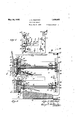
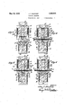
in which z-f' n Fig. 1 is a side elevation of a stapling machine made according to and embodying the principles of this invention; Fig. 2 is a longitudinal vertical section through the same, drawn on an enlarged scale; Figs. 3, 4, 5 and 5 6 are transverse sections, taken on line --aa devices, together with material clamping and clinching mechanism.
in Fig.- 2, and respectively showing various stages in the operation of the machine', Fig. 3 showing the normal initial osition of theseveral devices of the same, ig. 4 the material clamping and staple forming operations, Fig. 5 the staple driving operation, and Fig. 6 the staple clinching operation.
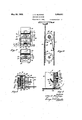
Fig. 7 is a transverse section, taken on line 7-7 in Fig. 2; Fig. 8 is a fragmentary horizontal section, taken on line 8-8 in Fig. V2; 60 Fig. 9 is an enlarged fragmentary vertical section, illustratngthe manner of retracting the staple forming anvil Iduring the staple driving operation; andFig. 10 is a transverse section, taken on line 10-10 in Fig. 2.
Similar characters of' reference are employed in all of the hereinabove described views to indicate corresponding parts.l
`Referring now to said drawings, the reference character 11 indicates the side or frame 510 'f plates of the machine. These plates are preferably stamped out of sheet metal, and when mounted on a suitable base '12, in laterally spaced apart relation, provide a housing for the operative parts of the mechanism. The J5 housing thus formed includes an upper arm 13 and a lower arm 14, vertically spaced apart to provide va material receiving space 15 therebetween. The .opposed margins of said upper and lower arms 13 and 14 ma4 be 30 notched, as at 16, for the reception an adjustable disposition of material stop means 17. The material stop means 17, as shown, is illustrative only, and may be variously ,modified or otherwise formed as desired. 95
The upper arm 13 of the housing carries the staple forming and driving mechanisms, whlethe lower arm 14 of the housing carries the material clamping-means and the staple Mounted in the upper arm 13, toextend transversely between the frame plates 11,
is a forward guide plate 18 and a rearward guide plate 19, said .plates 18 and- 19 having 95 ears 20 at their corners to engage in notches 2 1 formed in said frame plates 11, whereby said guide plates418 and' 19 are retained in assembled relation to the latter. The space between said guide plates 18 and 19 provides 100 appear.
a vertical slideway within which are mounted the staple forming and driving devices.
Mounted within thelower part of said arm 13 of the housing for rearward yielding movement, against the tension of -a positioning spring 22, isan anvil member 23. This anvil member 23 possesses a downwardly and forwardly inclined anvil face 24 of a width approximately the width of the staples desired to be formed. Said anvil 23 is slidably supported by a tail-piece 25 having lateral lugs 26 slidable in slots 27 formed in the frame plates 11. The spring 22 is anchored on a cross-barl28, which also aids in holding the frame plates 11 in spaced assembled relation, and said spring 22 is connected with said tail-piece 25 by an anchor hook 29, or any other suitable fastening means. The guide- plates 18 and 19 are suitably cut away at their lower portions to pass said anvil 23.
The staple forming means, which is cooperative with said anvil 23, comprises a vertically movable former plate 30 subdivided at its lower portion to provide laterally 'spaced apart bender legs 31, which, on. operative descent of said former plate 30, straddle the anvil 23. Secured to the face of said former plate 30 and movable therewith, and also shaped to correspond thereto, is a separator plate 32, having chamfered lower mar-v ginal ends 33 extending slightly below or beyond the extremities of said bender legsv 31, and the functions of which will subsequently Secured to the upper end of said former plate 30, by an oit-setting yoke or connection 34, is a rearwardly off-set actuatorplate 35. Said actuator plate 35 carries a stud 36 to cooperate with a former cam to be hereafter described. Suitably disposed springs 37 are interconnected between the former plate 30 and frame plates 11 to bias the former', and the separator plate 32 secured thereto, to normal initial raised posit-ion.f
The staple driving means, comprises a driver or punch plate 38 vertically and independ- -ently movable in the space 39 between the legs 31 of the former plate 30, lthus being of a width approximately the width of the formed staple. and movable with said driver or punch plate 38 is an anvil reti-actor plate 40. The lower end of said retractor plate projects slightly beyond the lower extremity of the driver or punch plate 38 and is chamfered or beveled, as at 41 (see Fig. 9), to conform to and engagewith the inclined surface of the anvil 23. Secured to the driver or punch plate 38, andthe retractor plate 40 secured thereto, isa stud 42 to cooperate with a driver cam to be hereafter described. The rearward Iguide plate 19 is centrally slotted, as at 43,
to permit unobstructed movement of said l stud 42 during vertical movement of the parts carrying the same. Suitably disposed springs 44 are interconnected between the Secured to the rear face of l frame plates l11 and an anchor bracket 45 carried by the driver and retractor plates to bias the latter to normal initial raised positions.
A wire blank supply magazine is detachably mounted in connection with the upper arm 13 of thev housing provided by the frame plates 11, andthe same comprises a pair of laterally opposed channeled side members 46 ,suitably connected together by cross bars 47. The upper of said cross bars 47 is provided with suspension hooks 48 to removably engage over a supporting bar49 secured to and between the side frames 11. rlhe lower end of the magazine is curved to enter through a slot 50 in the forward guide plate 18 in opposition to the anvil 23, and so as to discharge the wire blanks 51 by gravity successively upon and across the anvil 23 and beneath the nor-.
mally raised staple former and driver devices. A leaf spring 52anchored on a cross bar 52', which is also secured to and between the frame plates 11, and which is arranged to yieldably -press the discharge end of the magazine into said operative blank delivery position. The wire blanks 51 are initially straightand cut to suitable length, according to the size ofstatherefrom as the stapling machine is successively operated.
Mounted in the lower arm 14. to extend transversely between the frame plates 11, is
`a forward guide plate 53 and a rearward guide plate 54, said plates having ears 55 at their corners to engage in notches 56. formed in said frame plates 11, whereby sald guide plates 53 and 54 are retained i'n assembled relation to the latter. The space between said guide plates 53 and 54 provides a vertical slideway within which are mounted the material clamping and staple clinching devices.
The material clamping means, comprises a vertically movable clamp carrier plate 57, having at its upperend a rearward extension 58 terminating in a rearwardly off-set actuator plate 59. Said actuator plate 59 carries a fixed roller stud 60 to cooperate with a y clamper cam to be hereafter described. Fixed on the extension 58 at the upper end of said carrier plate'57, and so as to be exteriorlydisposed relative to the lower arm 14 of the housing, is a horizontal clamp member 61, having a transverse slot 62 therein for purposes hereafter described.
The staple clinching means comprises a pair of clincher dogs or levers 63, whichare pivotally mounted, for vertical oscillation, on pivot studs 64 which are in turn ailixed to laterally projecting ears 65 with which the upper end of said carrier plate 57 is provided.
The free ends of said clincher dogs or lev vers 63 extend one toward` the other, and are lboth normally engaged by the central lift cam portion 66 of 'a clincher plate 67. Said clinchcr plate 67 is vertically movable in a space between the forward guide-plate 53 and said carrier plate 57, and said clincher dogs or levers 63 are also' aligned in the plane of such space. The clincher plate carries a rearwardly projecting stud 68 which projects through 0 clearance slots 69 and 70 respectively provided in said carrier plate 57 and said rearward guide plate 54, so that such stud is operatively engageable by the clincher cam hereafter described, The carrier plate 57 and clincher plate 67 are biased by gravity to normal downward initial positions. The clincher dogs or levers 63 possess staple striking portions 63, which, when said dogs or levers are actuated, project through the slot 62 of the clamp member 61 to operatively engage and clinch over the free ends of the staple legs.
Mounted in bearings for extension through the upper arm 13 of the housing is a rotatable cam shaft 71. Said bearings preferably comprise transverse plates 72 to extend between the frame plates 11 of the housing, said plates y72 having lugs 73 at their extremities engage- `able in slots 74 provided in said frame plates 11, whereby the plates are rigidly supported. Preferably a pair of such plates 72 having oppositely projecting bearing sleeves 75, are arranged back to back so as together to form the bearing as a whole.
`Fixed on the forward end'of said cam shaft 71 is a former cam 76 to engage the stud 36 of the actuator plate 35; and also fixed on said forward end of said c a'm shaft 71 is a driver cam 77 to engage the stud 42 of the driver plate 38.
-Mounted in bearings for extension through the lower arm of said housing .is a rotatable cam shaft 78. The bearings for said cam shaft 78 are preferably constructed and mounted in the same way as those for the cam1 shaft 71,v and are identified as to their detail structure by the same reference characters. The cam shaft 78, however, is mounted so as to be capable of a limited vertical oscilla.
tion or play at its forward cam carrying end, for purposes presently to be made clear. this endthe slots 79 in the frame plates l1 which are engageable by the lugs 73 of the.
rearward bearing are so shaped as to permit pivotal swingor oscillation of said .bearing 5 in vertical plane, while the slots80 in the frame plates 11 which are engageable by the lugs 73 of the forward bearing are elongated to permit of substantially vertical movement of said forward bearing, so that at proper times the forward cam carrying end of said cam-shaft 78 may yield downwardly against the tension of a relatively stiff leaf spring 81, which'is fixed between the frame plates 11 to bear or thrust upwardly against the forward bearing of said cam shaft 78.
tion is made for vhand o Fixed on the forward end of said cam shaft 78 is a clamper cam 82 to engage the roller stud 60 of the material clampin means; and also fixed on said forward en shaft 78 is a clincher cam 83 to engagethe stud 68 of said clincher plate 67. l
When the stapling machine of this inven v ration, the cam shafts 71 and 78 may be driven by a rack and pinion actuating means. shown in the drawings, such actuating means comprises a gear or pinion 84 fixed on cam shaft 71 and a similar gear or pinion 85-xed on the cam shaft 78. Vertically slidable between guide lugs 86, formed atthe linner side of one yof the frame platesll, is a rack plate 87 which meshes with said gears or pinions 84 and 85. 'The upper free end. of said rack plate projects above the frame plates 11, and is provided with a hand plate 88. Said rack- In one form, as P of said cam plate 87, and consequently the cam shafts and transmission means (not shown) from any.
suitable power source. To utilize the stapling mechanism as a wire stitching machine for binding pamphlets, and similar work, the
cam shafts may be completely rotatedandA the work shifted between the arms 13 and 14 of the housing, as will be obvious, ora series of stapling mechanisms may be arranged to drive staples simultaneously through the work. l
1 The novel stapling machine operates as folows The material to' be bound,yas e. g. a' plu-- rality of paper sheets 92, is inserted in the opening 15 between the housing arms 13l and 14, whereupon rotary motion is imp arted to the cam shafts 71 and 78, which operate together to in turn rotate the various cams controlling the effective movements of the material clamping, and staple forming, driving and clinching mechanisms. clamper cam 82 and the former cam 76 are so set on their respective shafts 71 and-7 8 The that they operate together during the initial stages of the rotation of said shafts. The clamper cam 82 leads the clincher cam 83, and consequently -the clamper cam 82 acts first to raise the 'clamp' plate 61so that the material 92 is clamped between said clamp plate and the arm. 13 of thev housing' formed by the frame plates 11, while theclincher plate 67 remains'A retracted.
lasl
This initial movement of the clamp plate 61 relative to the clincher plate 67 allows the clincher dogs or levers 63 to dropv down preparatory to their effective staple clinching strokes (see Fig. 4) lf, due to the Athickness of the sheets of material 92, the
' sequently the clincher plate yields equally downward with the clamper cam, both cams ybeing fixed on the camshaft 78. Simultaneously with the operation of the clamper cam, the former camA 76 on the cam shaft 71 also operates to carry downward the former plate and separator plate 32, so that as the material is being clamped, a staple is being formed ready to be driven through the material. The wire blank magazine, prior to the descent of the former plate 30, delivers,
by gravity, a wire blank 51 upon the anvil 23 (see Figs. 2 and 3). The inclined face 24 of the anvil 23 is preferably provided with a slight transverse -indentionforming a seat s (see Fig. 9 vmore-particularly) which sus- -tains the wire blank against the thrust of the bender legs 31 of the former plate 30, and thus prevents untimely rearward yielding of the anyil. The separator plate .32 being rigidly connected with the -former plate 30 partakes of thedescending movementof'the latter, and said separator plate is provided with the chamfered edges 33 which slightly lead the ends of the bender legs 31 i-n such descent. The chamfered edges of the separator plate thereby enter between a wire blank 51 deposited on the anvil and the stack vof wire blanks remaining in the magazine, and consequently said separator plate is interposed between the same sodas to hold back the supply of wire blanks while a given wire blankA is being operatedv upon (see Fig. 9) As the former plate 30 de.
scends under the thrust of the former cam 76, the bender legs 31 engage the ends of the wire blank 51, which respectively project from opposite sides of the anvil, and thereupon bend downward such ends against the sides of the anvil, so as to form from the wire blank a U-shaped staple-ready to be driven through ythe material 92 (see Fig. 3). The
'i former vcam 76 and 'driver cam 77 are relaj so that the former cam leads the driver ca rn L suiiiciently to assure completion of the op tively fixed in position on the cam shaft 71 erative stroke of the former plate, and consequent formation of the staple, prior to any operative movement being transmitted to the driver plate 38. i
The material 92-having been clamped and the stapleyformed, the continued rotation of the cam shafts 71 and 78 moves the peaks of the clamper and former cams relative to the shafts 71 and 78 is such that driver cam leads the clincher cam suficiently to assure completion of the operative stroke of the driver plate 38, prior to any operative movement lbeing imparted to the clincher means.
As the driver plate 38 is caused to descend, the anvil retractor plate 40, which is rigidly fixed thereto, also descends. Said retractor plate possesses a beveled edge 41, which slightly leads the driver plate, and engages the inclined face 24-of the anvil 23, thus operating to thrust back or retract said anvil from the path of the staple, as the latteris engaged and driven downward by the driver plate 38 (see Fig. 9). The descent of the ldriver plate thus drives down the staple so that its legs are caused to pierce and pass through the materials, so as to be thereupon disposed through the opening 62 of the clamp plate 61, and in the path of movement of the clincher `dogs or levers 63 (see Fig. 5). It will be noted that the staple is entirely supported on all sides against any displacement from its straight downwardly directed position while being driven through the material 92, since lateral movement thereof is prevented by the bender legs 31, rearward tilting movement by the retractor plate and forward tilting movement by the separator plate 32. v
After the driver plate 38 completes its staple driving movement, the clincher cam 83 is timed to operatively engage the stud 66 of the clincher plate 67 to slide the lattervnpward. The upward movement of said clincher plate 67 carries its cam portion 66 into lifting engagement'with the pivoted clincher dogs or levers 63, thereby swinging the same upward. z The upward swing of the clincher dogs or levers 63 carries their striking portions 63 against the outer sides of the leg portions of the staple, depending from the material, thereby bending said legs inward.- ly and upwardly against the underside of the material, thus clinching the staple in operative attached relation to said material (see Fig.'6).
When the stapling machine is hand operated by the rack and pinion devices,lthe
- several cams and devices operated thereby lerated thereby completion of the clincher cam movement effected by the time the rack reaches the bottom of its stroke, whereupon, by releasing the `rack, the spring 89 will reverse the rotation of the cam shafts 71 and 78, and thus bring the back to normal initial positions. If the stapling machine is power driven, continued complete rotation of the cam shafts 7 1 and 78 will likewise bring the cams and devicesoptions.
l am aware that many changes could be made in the above described construction and many afp arently widely different embodiments o t 's invention could be made without departing from the scope thereof, and consequently it is intended that all matter con-v v tained in the above description or shown in formed staple stock upon said anvil means,
staple forming means cooperative with said anvilmeans, staple driving means, anvil retractor means connected with said driving means and having an end projected beyond the latter to engage the inclined face of said v anvil means to retract the same progressively in advance of the driving movement of said driving` means, staple clinching means, and.-
rotatively actuated cams arranged in operative timed relation to actuate said clamping means and said staple forming, driving and clinching means in sequence.
2. lin a stapling machineV having a'housing providing upper and lower spaced arms between which the material to bevboundv is inserted, a movable clamping means mounted in connection with said lower arm, an an. vil means mounted in connection with said upper arm, means to deliver unformed staple stock upon said anvil means, staple forming means mountedin connection with said upper arm and cooperative with said. anvil means, staple driving means also mounted in connection with said upper arm, anvil re tractor means connected with said driving means, staple clinching means mounted in connection with said lower arm, rotatively actuated cams mounted in said lower arm to actuate said clamping and clinching means, and rotatively actuated cams mounted in said upper arm to actuate said forming and driv ing means, said cams being arranged inoperative timed relation to actuate'said clamp-v ing'means and said staple forming, drivmg and clinching means in sequence.
back to normal initial posi-V 3. In a lstapling machine having a housing providing upper and lower spaced arms between which the material to be bound is inserted, a movable clamping means mounted in connectionwith said lower arm, an anvil means mounted in connection with saidupper arm, means to deliver unformed staple stock upon said anvil means, staple forming. means mounted .in connection with said upper arm and cooperative with said anvil means, staple driving means also mounted in connection with said upper arm, v anvil retractor` means connected with said driving means, staple clinching means mounted in connection with sa1d lower arm, rotatively actuated cams mounted 1n said lower armv to actuate said-clamping and clinching means,
rotatively actuated cams mounted in said upper, arm to actuate said forming and driving means, said cams being arranged in op erative timed relation to actuate said clamp` 4ing means and said staple forming, driving means is in operative engagement with the material to be ound.`
4:, In' a stapling machine, retractable an-ll l.
vil means, means vto deliver straight wire blanks upon said anvil means, a vertlcally reciprocable former plate having bender legs to straddle said anvil means, a separator c plate movable with said formerplate to separate succeeding wire blanks from the blank operativelydeposited on said anvil means,
a vertically movable driver plate inde endently slidable between thebender legs o said former late, an anvil retractor platemovable with said driver plate, means for clamping material to be bound subjeet'to the insertion therethrough by said driver plate of a staple formed by vsaid former plate, means .to cllnch the so inserted staple, and means 'to actuate said former plate and driver plate lin se uence.
5. n a stapling machine, a retractable anvil means, means to deliver straight wire blanks upon said anvil means, a vertically reciprocable former plate having bender legs to straddle said anvil means, a separator plate movable with said former plate to separate succeeding wire blanks from the blank op-. deposited on said anvil means, a
erative] verticallyV movable driver plate independently slidable'between the bender legs of said former plate, an anvil retractor platev movable with said driver plate, a vertically movable clamp carrying vplate having clamp pieans to support material to be bound subisc ject tothe driving of a formed staple therethrough, staple clinching devices also carvertically movable driver plate independently slidable between the bender legs of saidformer plate, an anvil retractor'plate movable with said driver plate, a vertically movable clamp carrying plate having clamp means to support material to be bound subject to the driving of a formed staple therethrough, staple clinching devices also cai"-A ried by said carrying plate, a vertically movable llift plate for actuating said clinching devices, and rotatively actuated cams to operate said clamp carrying plate, former plate, driver plate and lift plate in timed relation.
7 In a stapling machine, an yanvil means approximating the width of a stapleA to be formed, a magazine to hold a stack of straight wire blanks-of predetermined length, said magazine being arranged to successively .feed said blanks to said anvil means for transversely disposed position thereon, a staple forming means having bender legs to straddle said anvil, a separator platemovable with said staple forming means to separate the deposited blank from thosein the magazine y preparatory to staple forming and driving operations, staple driving means, anvil re-' tractor means movable with said driving means, means to clamp material to be bound subject to driving a formed staple therethrough, staple clinching means, and rotatively actuated cams arranged in operative timed relation to actuate said clamping means and staple forming,driving and clinching 1 meansin sequence.
'8. In a stapling machine having a housing providing upper and lower spaced .arms between which material to be bound'isgjinserted, a retractable anvil means in saidf'ipper arm, a -magazine to holda1stack` of straight wire blanks of predetermined length,
said magazine being arranged to successively feed said blanks to said anvil means for transversely disposed position thereon, a ver- .v tically reciprocable former plate having bender legs to straddle said anvil means, a-
separator plate movable with: said former plate to isolate the deposited blank from the supply thereof, a driver plate vertically and independently movable between the bender legs of said former plate, an anvil retractor plate movable with said driver plate, movable means supported in said lower arm .for
means, and rotatively actuated cams for operating .said clamping means, former plate, driver plate and linching means in timed relation. .1 v,
9. -In a staplingmachine having a housing providing upper, andlower spaced arms between which material to be bound is inserted, a vretractable anvil means in said upper arm, a magazine to hold. a stack of straight wire blanks of predetermined length, said magazine being arranged tofsuccessi-vely feed said blanks to lsaid `anvil ,means for transversely disposed position thereon, avertically reciprocable former plate having bender legs to straddle said anvil means, a separator plate movable with said former plate to isolate the deposited blank from the supply thereof, a driver plate vertically and independently movable between the bender legs of said former plate, an anvil retractor plate movable ly actuated cams for operating said clamping means, former plate, driver platel and clinching means in timed relation, a cam shaft mounted in said upper arm to `actuate the cams of operating said former plate and driver plate a cam shaft. mounted in said lower arm to actuate the cams of operating said clamping means and clinchin means, and spring means for holding said latter shaft and its cams subject to downward yielding movement when said clamping means is in operative engagement with the material to be bound. Y
10. In a stapling machine having a housing providing upper and' lower spaced'arms between which material to be bound is inserted, a retractable anvil means in said upper arin, a magazine to hold a stack of straight wire blanks of predetermined length, said 'magazine being arranged to successively feed said blanks tosaid anvil means for transversely disposed position thereon, a vertically reciprocable former plate having bender legs to straddle said anvil means, a separator plate movablewith said former plate to isolate the deposited blank from thel supply thereof, a driver plate vertically and independently movable between the bender legs of said' former plate, an anvil retractor plate movable with said driver plate, a vertically movable clamp carrying plate having clamp means to hold material to be bound, staple clinching devices pivotallycarried by said carrying plate, said clam means having an opening through which said clinching devices operate, a vertically movable lift plate for actuating said lift plate, and means for actuating said clamp means, former plate, driver plate and-lift plate in timed relation.
iso
nemen disposed blank from the supply thereof, a-
driver plate vertically and independently movable between the bender legs of said former plate, an anvil retractor plate movable with said driver plate, a vertically movable clamp carrying plate having clamp means to hold material to be bound, staple clinching devices pivotally carried by said carrying plate, said clamp means having an opening through which said clinching devices 3, includin rack and pinion means, for operatin sai cam shafts. l
14. staplin machine as defined in claim 9, including rac and pinion means for operating said cam shafts.
' 15, A stapling machine as deined in claim 12, including rack and pinion means for operating sai'd cam shafts.
In testimon that I claim the invention set forth above I ave hereunto set my hand this 4th dayl of November, -1929.
f JOHN C. BLEVNEY.
operate, a vertically movable lift plate for actuating said lift plate, and rotatively actuated cams for operating said clamp carrying plate and its clamp means, former plate, driver plate and lift plate in timed relation.
12. In a stapling machine having a housserted, a retractable anvil means in said upper arm, a magazine to 'hold' a stack of straight wire blanks of predetermined length,
I ing providing upper and lower spaced arms between which material to'be bound is insaid magazine being arranged to successively feed said blanks to said anvil means for transversely disposed position thereon, a vertically reciprocable former plate having bender legs to straddle said anvil means, a separator plate y movable with said former plate to isolate the,
4W disposed blank from the' supply thereof, a driver plate vertically and 1nd -ipendently`A movable between the bender legs of said able with sai lformerv plate an anvil retractor late movd driver plate, a vertically movable clamp carrying 'plate havin clamp means to hold material to be boun staple clinching devices ivotally carried by said carrying plate, sai clamp means4 having an opening through which said clinching devices operate, a vertically'movable lift plate Yfor .actuating said staple clinching devices rotatively actuated cams for operating said clamp'carrying plate and its clamp means,l former plate, driver Aplate and lift late in` timed relation, a cam shaft mounte in said upper arm to actuate the cams operating said former late'and driver. plate, aocam shaft mounte in said lower arm to actuate the cams o rating said clamp carrying late and saidli plate, andsprin'gmeansfor olding said latter shaft and its cams subject to downward- Ayielding movement when' said clamping means is 1n o rative engagement with the material to be und. j
13. A 'stapling machine. as defined in claim lll.
Priority Applications (1)
| Application Number | Priority Date | Filing Date | Title |
|---|---|---|---|
| US404897A US1859951A (en) | 1929-11-05 | 1929-11-05 | Stapling machine |
Applications Claiming Priority (1)
| Application Number | Priority Date | Filing Date | Title |
|---|---|---|---|
| US404897A US1859951A (en) | 1929-11-05 | 1929-11-05 | Stapling machine |
Publications (1)
| Publication Number | Publication Date |
|---|---|
| US1859951A true US1859951A (en) | 1932-05-24 |
Family
ID=23601487
Family Applications (1)
| Application Number | Title | Priority Date | Filing Date |
|---|---|---|---|
| US404897A Expired - Lifetime US1859951A (en) | 1929-11-05 | 1929-11-05 | Stapling machine |
Country Status (1)
| Country | Link |
|---|---|
| US (1) | US1859951A (en) |
Cited By (13)
| Publication number | Priority date | Publication date | Assignee | Title |
|---|---|---|---|---|
| US2590088A (en) * | 1947-04-30 | 1952-03-25 | Robert W Clauss | Pinticket manufacturing and attaching machine |
| US2827630A (en) * | 1955-07-05 | 1958-03-25 | Gen Mills Inc | Machine for mounting electrical components |
| US2893009A (en) * | 1955-02-15 | 1959-07-07 | Gen Mills Inc | Machine for assembling circuit components |
| US2896208A (en) * | 1956-09-05 | 1959-07-28 | United Shoe Machinery Corp | Component inserting machines |
| US2903698A (en) * | 1957-02-13 | 1959-09-15 | United Shoe Machinery Corp | Machines for mounting electronic components |
| US2903697A (en) * | 1954-07-13 | 1959-09-15 | Sylvania Electric Prod | Automatic assembly apparatus |
| US2904786A (en) * | 1955-03-10 | 1959-09-22 | Melpar Inc | Stapling machines |
| US2904785A (en) * | 1954-03-01 | 1959-09-22 | Melpar Inc | Stapling machine |
| US2928093A (en) * | 1954-12-28 | 1960-03-15 | Gen Mills Inc | Assembling machine for circuit components |
| US2982967A (en) * | 1957-05-24 | 1961-05-09 | Sperry Rand Corp | Apparatus for installing components |
| EP1541291A1 (en) * | 2002-07-26 | 2005-06-15 | Max Co., Ltd. | Stapler and cartridge |
| US9592597B2 (en) | 2013-01-23 | 2017-03-14 | Worktools, Inc. | Flat clinch stapler anvil assembly |
| US9987734B2 (en) | 2013-01-23 | 2018-06-05 | Worktools, Inc. | Flat clinch anvil assembly |
-
1929
- 1929-11-05 US US404897A patent/US1859951A/en not_active Expired - Lifetime
Cited By (15)
| Publication number | Priority date | Publication date | Assignee | Title |
|---|---|---|---|---|
| US2590088A (en) * | 1947-04-30 | 1952-03-25 | Robert W Clauss | Pinticket manufacturing and attaching machine |
| US2904785A (en) * | 1954-03-01 | 1959-09-22 | Melpar Inc | Stapling machine |
| US2903697A (en) * | 1954-07-13 | 1959-09-15 | Sylvania Electric Prod | Automatic assembly apparatus |
| US2928093A (en) * | 1954-12-28 | 1960-03-15 | Gen Mills Inc | Assembling machine for circuit components |
| US2893009A (en) * | 1955-02-15 | 1959-07-07 | Gen Mills Inc | Machine for assembling circuit components |
| US2904786A (en) * | 1955-03-10 | 1959-09-22 | Melpar Inc | Stapling machines |
| US2827630A (en) * | 1955-07-05 | 1958-03-25 | Gen Mills Inc | Machine for mounting electrical components |
| US2896208A (en) * | 1956-09-05 | 1959-07-28 | United Shoe Machinery Corp | Component inserting machines |
| US2903698A (en) * | 1957-02-13 | 1959-09-15 | United Shoe Machinery Corp | Machines for mounting electronic components |
| US2982967A (en) * | 1957-05-24 | 1961-05-09 | Sperry Rand Corp | Apparatus for installing components |
| EP1541291A1 (en) * | 2002-07-26 | 2005-06-15 | Max Co., Ltd. | Stapler and cartridge |
| EP1541291A4 (en) * | 2002-07-26 | 2005-09-28 | Max Co Ltd | Stapler and cartridge |
| US20050269380A1 (en) * | 2002-07-26 | 2005-12-08 | Toshio Shimizu | Stapler and cartridge |
| US9592597B2 (en) | 2013-01-23 | 2017-03-14 | Worktools, Inc. | Flat clinch stapler anvil assembly |
| US9987734B2 (en) | 2013-01-23 | 2018-06-05 | Worktools, Inc. | Flat clinch anvil assembly |
Similar Documents
| Publication | Publication Date | Title |
|---|---|---|
| US1859951A (en) | Stapling machine | |
| EP0549513B1 (en) | Stapling machine for spring carcass frames | |
| US970461A (en) | Wire-stitcher. | |
| US3661039A (en) | Cutting and assembling apparatus for making buttons | |
| US4444347A (en) | Stapling device for use with wire staple supply | |
| US2267990A (en) | Stapling machine | |
| JP4952129B2 (en) | Stapler | |
| JP2008044058A (en) | Stapler | |
| US1154969A (en) | Box-making machine. | |
| US1933031A (en) | Machine for use in making boxes | |
| US1594851A (en) | Combination binding machine | |
| US1491272A (en) | Buckle-fastening machine | |
| US2360115A (en) | Mattress stapling machine | |
| US1125969A (en) | Tag-machine. | |
| US263391A (en) | Book-stapling machine | |
| US542005A (en) | And thomas | |
| JPH0111426Y2 (en) | ||
| US1036841A (en) | Stapling-machine. | |
| US1581288A (en) | Stapling machine | |
| US487679A (en) | Machine for making package-carriers | |
| US1491273A (en) | Stapling machine | |
| JP4882590B2 (en) | Stapler | |
| JP4967522B2 (en) | Stapler | |
| US112719A (en) | Improvement in machines for making and setting blind-staples | |
| US1773510A (en) | Machine for use in making boxes |