US1859950A - Core catcher - Google Patents
Core catcher Download PDFInfo
- Publication number
- US1859950A US1859950A US465477A US46547730A US1859950A US 1859950 A US1859950 A US 1859950A US 465477 A US465477 A US 465477A US 46547730 A US46547730 A US 46547730A US 1859950 A US1859950 A US 1859950A
- Authority
- US
- United States
- Prior art keywords
- core
- barrel
- entrance
- gripping
- chains
- Prior art date
- Legal status (The legal status is an assumption and is not a legal conclusion. Google has not performed a legal analysis and makes no representation as to the accuracy of the status listed.)
- Expired - Lifetime
Links
Images

Classifications
-
- E—FIXED CONSTRUCTIONS
- E21—EARTH DRILLING; MINING
- E21B—EARTH DRILLING, e.g. DEEP DRILLING; OBTAINING OIL, GAS, WATER, SOLUBLE OR MELTABLE MATERIALS OR A SLURRY OF MINERALS FROM WELLS
- E21B25/00—Apparatus for obtaining or removing undisturbed cores, e.g. core barrels, core extractors
- E21B25/10—Formed core retaining or severing means
Definitions
- My Vinvention relates to core barrels used in the well-drilling art for taking samples of the subterranean strata, and it consists of type now employed has a plurality of upwardly extending spring fingers adapted to frictionally engage the core when the core barrel is raised, and to break the core near where it projects from the bottom of the well, and to raise it to the top of the well.
- the spring fingers engage the core and have a cutting action on the wall thereof. This action reduces the diameter of the core and breaks it into sections which must be properly aligned when the core pieces are removed.
- the sprmg fingers are not positive 1n operation and usually a portion of the corel is lost, which of course means that the core record of the well will be incomplete.
- a further obj ect of my invention is to provide a core barrel having a core-catching means which, during the forming of the core, occupies a: position in which it will not engage the core to wear it down or break it up.
- a still further object of my invention is to provide a core barrel having-core-catching means which will move into core-gripplng position upon the initial upward movementl .f of the core barrel and will cause the core to break at the lower end of the core barrel.
- My invention in its broad concept provides a core-catching means which includes a mem- -in any type of core barrel.
- a core-catching means which includes a mem- -in any type of core barrel.
- Positioned ber positioned in the entrance of the corereceiving barrel. This member is movable from a non-gripping position during the forming of the core into a gripping position.
- the member '55 is made flexible or pliable and is moved into and from its different positions by friction of the core, and the flexible member is more or less floating except when it is'in gripping position.
- the flexible member of the preferred form of my invention is embedded in a body of rotary mud which surrounds the core in the entrance. This prevents the core from being worn or broken by the core-catching means.
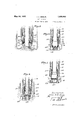
- Fig. 1 is an elevational sectional view through a core barrel embodying the first form of my invention, the core-catching means being in non-gripping position. 75
- Fig. 2 is a section like Fig. 1, with the corey. catching means in gripping position.
- Figs. 3' and 4 are sections taken on the in- 'dic'ating lines of Fig. 2.
- Figs. 5 to 8, inclusive are fragmentary vertical sectional views showingfour other embodiments of my invention.
- the core-catching means of my invention may be used purposes I have shown a somewhat general type of core barrel which includes (as shown best in Fig. 1) a shell 11, to the lower end of which a head 12 is joined by means of a connector 14.
- the head 14 is internally threaded at 15, and threadedly receives a threaded pin 16 of a cutter body 17.
- Cutter wings 19 eX- tend outward from the cutter body 17, they being supplied with rotary mud fluid by pas- 95 within the shell l1 1s a core-receiving barrel 22.
- the lower end of which has a shoulder 23 which rests between an internal annular ledge 24 of the body 12 and the upper end of the threaded pin 16.
- the cutter body 17 has an entrance 26 of cylindrical cross-section which connects to the interior of the core-receiving barrel 22.
- the entrance 26 is defined by a cylindrical wall 27 and a conical or tapered wall 28.
- the core identiied by the numeral 3() is formed by rotating the core barrel, the wings 19 cutting away the bottom of the well around the core. As the core 30 is formed it extends upward into the entrance 26 and into the corcreceiving b arrel 22.
- Figs. 1 to 4 inclusive, has one or more members 33 which are lineal, eXible or pliable members.
- the members 33 are link chains.
- One end of each chain 33 is secured tothe cutter body 17 so that it rests in the entrance 26.
- a convenient way of vattaching the chains 33 is to form openings 34 in the cutter body 17 and secure the ends of the chains 33 by welded plugs 35 formed in the openings 34.
- the chains 33 are free in the entrance 26 and are caused to assume a position in the entrance in accordance with the directionof friction or pressure against them. During the forming of the core, the chains 33 assume the position shown in Fig. 1. Since the core 30 ismoving upward through the entrance 26, and since the core barrel is rotating, ythe chains 33 are caused to occupy an upward spiral position, or in other words, a
- chains 33 are in the larger part of the entrance 26 where there is ample space for them around the core.
- the rotary mud fluid which is supplied to the core barrel and the cuttings and sediment enter the entrance around the core 30 and pack in it as indicated i bythe numeral 38.
- the chains 33 are practically embedded in the granular material 38, which acts as a retaining means dfor the chains and holds them away Jfrom the core,
- a length of core 30 When a length of core 30 has been formed, it may be raised to the surface of the ground by raising the core barrel.
- the chains 33 move from the position shown in Fig. 1 into a gripping position as shown in Fig. 2.
- the chains in this gripping position may still be wrapped around the core, but the free ends thereof rest in the tapered part of the entrance 26 and are caused to firmly. grip the core 30, so as to sever it from the bottom of the well and enable raising it to the 'surface of the ground.
- the packed granular material 38 so far as I can now determine, assists in the gripping ⁇ of the core.
- the chains 33 will operate'the same as the chains in Figs. 1 to 4, but if the ring 60 remains nonrotatable, the chains will occupy axial positions, as shown. Notwithstanding, the chains will occupy either non-gripping or gripping positions-and Operate in about the same manmanner as the core-catching means ofv Figs. 1 to 4.
- Fig. 6 I show a form of my invention in which both ends of the core-catching members are attached to the cutter body wall at each end, thusleaving loops 64, as distinguished from the two forms of my invention already described, in which one end of each chain is free.
- the core-catching members are provided in the form of flexible springs which are connected at each end by welded plugs 34, as in the other forms of my invention. These springs are movable by the friction or pressure of the core from non-gripping position into gripping position and vice versa.
- the form of the invention shown in Fig. 8 has the core-catching means in the form of iiexible cables 67.
- the cables 67 may grip the core 30, they'may be provided with enlargements 68 which may be welded thereon. l
- core-catching means including a chain-like member movable from non-gripping to gripping positions.
- core-catching means including a chain-like member, free at one end and secured to said core barrel at the other end, movable from non-gripping toI gripping positions.
- core-catching means including a ychain-like member, secured to said core barrel at both ends and. forming, a loop, movable from .nn-gripping to gripping positions.
- a core'barrel having a cutter, a corereceiving barrel, and an entrance through which the core entersV said core-receiving barrel, said entrance having a tapered portion
- core-catching means including a chain-like member in said entrance, said member being movable by said core from a non-gripping position into a gripping position in said tapered portion of said entrance'.v
- a core barrel having a cutter, a corereceiving barrel, and an entrance through which the core enters said core-receiving barrel, said entrance having a tapered portion
- core-catching means including.a chain-like member in said entrance adapted to wrap around said core, said member being movable by said core from a non-,gripping position into a'gripping position in said tapered portion of said entrance.
- a core barrel having a cutter, a corereceiving barrel, and an entrance through which the core enters said core-receiving barrel, said entrance-having atapered portion
- core-catching means including a.' chain-like member in said entrance, said member-being movable by said core from a non-gripping position into a gripping. position in'said tapered portion of said entrance; and an enlargement on said member to facilitate gripping of said core.
- a core barrel having a cutter, a corereceiving barrel, and an entrance through which the core enters said core-receiving barrel, said entrance having a tapered portion, the combination with: core-catching means including a chain-like member in said entrance adapted to Wrap around said c'ore,
- said member being movable by said core.
- core-catching means including a iexible member consisting of a link chain inv said entrance, said member being movablel by said core4 from a non-gripping position into a gripping position in said tapered portion of said entrance.
- a cutter for use on a core barrel a body having an entrance passage: cutting means on said body; and a chain-like member secured in said entrance.
- a cutter for use on a core barrel a body having an entrance passage: cutting means on'said body; and a chain-like member secured in said entrance, one end of said member being secured to said body.
- the combination W1th a cha1n-like member disposed in said entrance and having a portionof pliable'characteristics which enable it to embed .itself in the granular mateday of July, 1930.
Landscapes
- Life Sciences & Earth Sciences (AREA)
- Engineering & Computer Science (AREA)
- Geology (AREA)
- Mining & Mineral Resources (AREA)
- Physics & Mathematics (AREA)
- Environmental & Geological Engineering (AREA)
- Fluid Mechanics (AREA)
- General Life Sciences & Earth Sciences (AREA)
- Geochemistry & Mineralogy (AREA)
- Drilling Tools (AREA)
Description
J. A. ZUBLIN CORE CATCHER v May 24, 1932.
Filed lJuly 3. 1930 2 Sheets-Sheet w E TZ N WN fw J. A. ZUBLIN May 24, 1932.
CORE CATCHER Filed Ju'ly 5, 1930 2 Sheets-ShamJ rTQe/vey.
PaieniedMey 24,1932 I PATENT OFFICE JOHN A. ZUBLIN, 0F LOS ANGELES, CALIFORNIA donn GATCHER Application inea July a, 1930. serial No. 465,477.
My Vinvention relates to core barrels used in the well-drilling art for taking samples of the subterranean strata, and it consists of type now employed has a plurality of upwardly extending spring fingers adapted to frictionally engage the core when the core barrel is raised, and to break the core near where it projects from the bottom of the well, and to raise it to the top of the well.
During the forming of the core the spring fingers engage the core and have a cutting action on the wall thereof. This action reduces the diameter of the core and breaks it into sections which must be properly aligned when the core pieces are removed. v
The sprmg fingers are not positive 1n operation and usually a portion of the corel is lost, which of course means that the core record of the well will be incomplete.
It is an object of my invention to provide a corebarrel in which a complete, full-size core may be taken, and in which the diameter of the core will not be reduced by the corecatching means.
It is another' object of my invention to provide Ia core barrel in which a part of the core will not be lost by the core-catching means.
A further obj ect of my invention is to provide a core barrel having a core-catching means which, during the forming of the core, occupies a: position in which it will not engage the core to wear it down or break it up.
A still further object of my invention is to provide a core barrel having-core-catching means which will move into core-gripplng position upon the initial upward movementl .f of the core barrel and will cause the core to break at the lower end of the core barrel.
My invention in its broad concept provides a core-catching means which includes a mem- -in any type of core barrel. For illustrative sages 20 formed in the head 12. Positioned ber positioned in the entrance of the corereceiving barrel. This member is movable from a non-gripping position during the forming of the core into a gripping position. v
In its preferred embodiments, the member '55 is made flexible or pliable and is moved into and from its different positions by friction of the core, and the flexible member is more or less floating except when it is'in gripping position. During the forming of the core the flexible member of the preferred form of my invention is embedded in a body of rotary mud which surrounds the core in the entrance. This prevents the core from being worn or broken by the core-catching means.
In the course of thefollowing description, various additional objects andespecial advantages will be emphasized. i
Referring to the drawings, which are for illustrative purposes only,
Fig. 1 is an elevational sectional view through a core barrel embodying the first form of my invention, the core-catching means being in non-gripping position. 75
Fig. 2 is a section like Fig. 1, with the corey. catching means in gripping position.
Figs. 3' and 4 are sections taken on the in- 'dic'ating lines of Fig. 2.
Figs. 5 to 8, inclusive, are fragmentary vertical sectional views showingfour other embodiments of my invention.
The core-catching means of my invention, irrespective of its embodiment, may be used purposes I have shown a somewhat general type of core barrel which includes (as shown best in Fig. 1) a shell 11, to the lower end of which a head 12 is joined by means of a connector 14. The head 14 is internally threaded at 15, and threadedly receives a threaded pin 16 of a cutter body 17. Cutter wings 19 eX- tend outward from the cutter body 17, they being supplied with rotary mud fluid by pas- 95 within the shell l1 1s a core-receiving barrel 22. the lower end of which has a shoulder 23 which rests between an internal annular ledge 24 of the body 12 and the upper end of the threaded pin 16. The cutter body 17 has an entrance 26 of cylindrical cross-section which connects to the interior of the core-receiving barrel 22. The entrance 26 is defined by a cylindrical wall 27 and a conical or tapered wall 28.
The core identiied by the numeral 3() is formed by rotating the core barrel, the wings 19 cutting away the bottom of the well around the core. As the core 30 is formed it extends upward into the entrance 26 and into the corcreceiving b arrel 22.
I will now describe the core-catching means which, of itself and in combination with the parts described, constitute my invention.
The form shown in Figs. 1 to 4, inclusive, has one or more members 33 which are lineal, eXible or pliable members. In these figures the members 33 are link chains. One end of each chain 33 is secured tothe cutter body 17 so that it rests in the entrance 26. A convenient way of vattaching the chains 33 is to form openings 34 in the cutter body 17 and secure the ends of the chains 33 by welded plugs 35 formed in the openings 34.
The chains 33 are free in the entrance 26 and are caused to assume a position in the entrance in accordance with the directionof friction or pressure against them. During the forming of the core, the chains 33 assume the position shown in Fig. 1. Since the core 30 ismoving upward through the entrance 26, and since the core barrel is rotating, ythe chains 33 are caused to occupy an upward spiral position, or in other words, a
wrapped position around the core 30. The.
' thus preventing a cutting down or breakage of the core.
When a length of core 30 has been formed, it may be raised to the surface of the ground by raising the core barrel. When the core barrel is raised, the chains 33 move from the position shown in Fig. 1 into a gripping position as shown in Fig. 2. The chains in this gripping position may still be wrapped around the core, but the free ends thereof rest in the tapered part of the entrance 26 and are caused to firmly. grip the core 30, so as to sever it from the bottom of the well and enable raising it to the 'surface of the ground. The packed granular material 38, so far as I can now determine, assists in the gripping `of the core.
r It is a part of the invention that the chains wrap themselves around the core, and they do this because the friction is in a spiral or helical direction. c
60 may or may not rotate, as desired, depending upon the closeness of fit in the counterbore 61. If the ring 60 rotates, the chains 33 will operate'the same as the chains in Figs. 1 to 4, but if the ring 60 remains nonrotatable, the chains will occupy axial positions, as shown. Notwithstanding, the chains will occupy either non-gripping or gripping positions-and Operate in about the same manmanner as the core-catching means ofv Figs. 1 to 4.
In Fig. 6 I show a form of my invention in which both ends of the core-catching members are attached to the cutter body wall at each end, thusleaving loops 64, as distinguished from the two forms of my invention already described, in which one end of each chain is free.
In Fig. 7 the core-catching members are provided in the form of flexible springs which are connected at each end by welded plugs 34, as in the other forms of my invention. These springs are movable by the friction or pressure of the core from non-gripping position into gripping position and vice versa. y
The form of the invention shown in Fig. 8 has the core-catching means in the form of iiexible cables 67. In order that the cables 67 may grip the core 30, they'may be provided with enlargements 68 which may be welded thereon. l
I claim as my invention:
. 1. In a core barrel having a cutter, a corereceivinofv barrel, and an entrance through which the core enters said core-receiving barrel, the combination with: core-catching means including a chain-like member movable from non-gripping to gripping positions.
2. In a core barrel having a cutter, a corereceiving barrel, and an entrance through which the core enters said core-receiving barrel, the combination with: core-catching means including a chain-like member, free at one end and secured to said core barrel at the other end, movable from non-gripping toI gripping positions.
3. In a core barrel having a cutter, a corereceiving barrel, and an entrance through which the core enters said core-receiving barrel, the combination with: core-catching means including a ychain-like member, secured to said core barrel at both ends and. forming, a loop, movable from .nn-gripping to gripping positions. Y
4. In a core'barrel having a cutter, a corereceiving barrel, and an entrance through which the core entersV said core-receiving barrel, said entrance having a tapered portion, the combination with: core-catching means including a chain-like member in said entrance, said member being movable by said core from a non-gripping position into a gripping position in said tapered portion of said entrance'.v
5. In. a core barrel having a cutter, a corereceiving barrel, and an entrance through which the core enters said core-receiving barrel, said entrance having a tapered portion, the combination with: core-catching means including.a chain-like member in said entrance adapted to wrap around said core, said member being movable by said core from a non-,gripping position into a'gripping position in said tapered portion of said entrance.
6. In a core barrel having a cutter, a corereceiving barrel, and an entrance through which the core enters said core-receiving barrel, said entrance-having atapered portion, the combination with: core-catching means including a.' chain-like member in said entrance, said member-being movable by said core from a non-gripping position into a gripping. position in'said tapered portion of said entrance; and an enlargement on said member to facilitate gripping of said core.
7. ln a core barrel having a cutter, a corereceiving barrel, and an entrance through which the core enters said core-receiving barrel, said entrance having a tapered portion, the combination with: core-catching means including a chain-like member in said entrance adapted to Wrap around said c'ore,
said member being movable by said core.
from a non-gripping'position into ay gripping position in said tapered portion of said er1-- trance; and an enlargement on said member to facilitate gripping-of said core. l
8. In a core barrel havinga. cutter, a corereceiving barrel, and an entrance through Which the core enters said core-receiving barrel, said entrance having a tapered portion, the combination with: core-catching means including a iexible member consisting of a link chain inv said entrance, said member being movablel by said core4 from a non-gripping position into a gripping position in said tapered portion of said entrance.
9. ln a cutter for use on a core barrel: a body having an entrance passage: cutting means on said body; and a chain-like member secured in said entrance.
l0. ln a cutter for use on a core barrel: a body having an entrance passage: cutting means on'said body; and a chain-like member secured in said entrance, one end of said member being secured to said body.
1l. In a core barrel having a cutter, a corerccciving barrel, and an entrance through which the core enters said core-receiving barrel, the combination W1th: a cha1n-like member disposed in said entrance and having a portionof pliable'characteristics which enable it to embed .itself in the granular mateday of July, 1930.
. JOHN A. ZUBLIN.
Priority Applications (1)
| Application Number | Priority Date | Filing Date | Title |
|---|---|---|---|
| US465477A US1859950A (en) | 1930-07-03 | 1930-07-03 | Core catcher |
Applications Claiming Priority (1)
| Application Number | Priority Date | Filing Date | Title |
|---|---|---|---|
| US465477A US1859950A (en) | 1930-07-03 | 1930-07-03 | Core catcher |
Publications (1)
| Publication Number | Publication Date |
|---|---|
| US1859950A true US1859950A (en) | 1932-05-24 |
Family
ID=23847968
Family Applications (1)
| Application Number | Title | Priority Date | Filing Date |
|---|---|---|---|
| US465477A Expired - Lifetime US1859950A (en) | 1930-07-03 | 1930-07-03 | Core catcher |
Country Status (1)
| Country | Link |
|---|---|
| US (1) | US1859950A (en) |
Cited By (3)
| Publication number | Priority date | Publication date | Assignee | Title |
|---|---|---|---|---|
| US4312414A (en) * | 1980-05-23 | 1982-01-26 | Diamond Oil Well Drilling Company | Method and apparatus for obtaining saturation data from subterranean formations |
| US4479557A (en) * | 1983-07-13 | 1984-10-30 | Diamond Oil Well Drilling Co. | Method and apparatus for reducing field filter cake on sponge cores |
| US10107055B2 (en) * | 2016-09-01 | 2018-10-23 | Baker Hughes, A Ge Company, Llc | Core catcher |
-
1930
- 1930-07-03 US US465477A patent/US1859950A/en not_active Expired - Lifetime
Cited By (3)
| Publication number | Priority date | Publication date | Assignee | Title |
|---|---|---|---|---|
| US4312414A (en) * | 1980-05-23 | 1982-01-26 | Diamond Oil Well Drilling Company | Method and apparatus for obtaining saturation data from subterranean formations |
| US4479557A (en) * | 1983-07-13 | 1984-10-30 | Diamond Oil Well Drilling Co. | Method and apparatus for reducing field filter cake on sponge cores |
| US10107055B2 (en) * | 2016-09-01 | 2018-10-23 | Baker Hughes, A Ge Company, Llc | Core catcher |
Similar Documents
| Publication | Publication Date | Title |
|---|---|---|
| US2150228A (en) | Packer | |
| US2699920A (en) | Apparatus for drilling laterally deviating bores from a vertical bore below a casing set therein | |
| US1804819A (en) | Side wall drilling organization | |
| US4817725A (en) | Oil field cable abrading system | |
| US2824613A (en) | Stop devices for well conduits | |
| US1859950A (en) | Core catcher | |
| US2229325A (en) | Deep well bridge | |
| US2922479A (en) | Apparatus for controlling fluid circulation | |
| JPS6078091A (en) | Core collecting apparatus | |
| US2577994A (en) | Overshot | |
| US3132707A (en) | Method and apparatus for vibrating well pipe | |
| US20210054711A1 (en) | Fishing neck for plunger | |
| US1509565A (en) | Fishing tool | |
| US2334428A (en) | Well device | |
| US3599735A (en) | Bumper sub and closed fluid circulation assembly | |
| US3282349A (en) | Casing centralizer | |
| US2026295A (en) | Fishing tool | |
| US1557480A (en) | Coupling and pipe packer | |
| US4089371A (en) | Production shoe | |
| US1491915A (en) | Float plug | |
| US2122602A (en) | Rotary automatic latch trip socket | |
| US1529544A (en) | Rotary jar | |
| US1657368A (en) | Core barrel | |
| US615321A (en) | Shot-anchor for oil-wells | |
| US1672321A (en) | Rotary jar |