US185993A - Improvement in running-gears for vehicles - Google Patents
Improvement in running-gears for vehicles Download PDFInfo
- Publication number
- US185993A US185993A US185993DA US185993A US 185993 A US185993 A US 185993A US 185993D A US185993D A US 185993DA US 185993 A US185993 A US 185993A
- Authority
- US
- United States
- Prior art keywords
- springs
- perches
- spring
- bearings
- plates
- Prior art date
- Legal status (The legal status is an assumption and is not a legal conclusion. Google has not performed a legal analysis and makes no representation as to the accuracy of the status listed.)
- Expired - Lifetime
Links
- 241000269800 Percidae Species 0.000 description 10
- 239000007787 solid Substances 0.000 description 7
- 235000000396 iron Nutrition 0.000 description 5
- 230000000284 resting effect Effects 0.000 description 5
- XEEYBQQBJWHFJM-UHFFFAOYSA-N Iron Chemical compound [Fe] XEEYBQQBJWHFJM-UHFFFAOYSA-N 0.000 description 4
- 238000010276 construction Methods 0.000 description 4
- 210000003128 head Anatomy 0.000 description 4
- 229910052742 iron Inorganic materials 0.000 description 4
- 229910000831 Steel Inorganic materials 0.000 description 3
- 230000035939 shock Effects 0.000 description 3
- 239000010959 steel Substances 0.000 description 3
- 238000012856 packing Methods 0.000 description 2
- 230000013707 sensory perception of sound Effects 0.000 description 2
- 241001661918 Bartonia Species 0.000 description 1
- 101100001669 Emericella variicolor andD gene Proteins 0.000 description 1
- 238000005452 bending Methods 0.000 description 1
- 238000005219 brazing Methods 0.000 description 1
- 210000000887 face Anatomy 0.000 description 1
- 239000000463 material Substances 0.000 description 1
- 239000002184 metal Substances 0.000 description 1
- 229910052751 metal Inorganic materials 0.000 description 1
- 210000003739 neck Anatomy 0.000 description 1
- 238000003466 welding Methods 0.000 description 1
Images
Classifications
-
- B—PERFORMING OPERATIONS; TRANSPORTING
- B65—CONVEYING; PACKING; STORING; HANDLING THIN OR FILAMENTARY MATERIAL
- B65D—CONTAINERS FOR STORAGE OR TRANSPORT OF ARTICLES OR MATERIALS, e.g. BAGS, BARRELS, BOTTLES, BOXES, CANS, CARTONS, CRATES, DRUMS, JARS, TANKS, HOPPERS, FORWARDING CONTAINERS; ACCESSORIES, CLOSURES, OR FITTINGS THEREFOR; PACKAGING ELEMENTS; PACKAGES
- B65D85/00—Containers, packaging elements or packages, specially adapted for particular articles or materials
- B65D85/30—Containers, packaging elements or packages, specially adapted for particular articles or materials for articles particularly sensitive to damage by shock or pressure
- B65D85/34—Containers, packaging elements or packages, specially adapted for particular articles or materials for articles particularly sensitive to damage by shock or pressure for fruit, e.g. apples, oranges or tomatoes
Description
2 Sheets-Sheet l.
E. D. WELLER.
RUNNING-GEAR FOR VEHICLES. No.185,993. Patented Jan.2, 1877.
2 Sheets-Sheet 2.
E. D. WELLER. RUNNING-GEAR FOR VEHICLES.
N Patented Jan. 2, 1877.
N.FETER$, PHOTO-LITHOGRAPMER, WASHINGTON D u UNITED STATES PATENT OFFICE.
EUGENE D. WELLER, OF LIMA, NEW YORK.
IMPROVEMENT IN RUNNING-GEARS FOR VEHICLES.
Specification forming part of Letters Patent No. 185,993, dated January 2, 1877; application filed June 6, 1876.
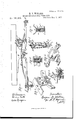
To all whom it may concern Be it known that I, EUGENE D. WELLER, of Lima, in the county of Livingston and State of New York, have invented a certain new and useful Improvement in Running-Gear for Vehicles; and I-do hereby declare that the following is a full, clear, and exact description of the construction and operation of the same, reference being had to the accompanying drawings, in which- Figure 1 is a plan of my improvement with the wagon-body and side bars removed from place. Fig. 2 is a vertical section of the same. Figs. 3, 4, 5, 6, 7, and 8 are detail views.
In general construction this invention is similar to that patented by me August 19, 1873, and is an improvement upon the same.
The invention consists in the construction and arrangement of the parts hereinafter described and specifically claimed.
In the drawings, A A represent the axles. B is the bolster. G O are the side springs,
. andD D are the side bars resting on top the springs, and supporting the wagon-body. E E are half-perches, made fast at rear and front, respectively, to the axle and bolster, and jointed in the center or intermediately to bearings made fast to the side springs. Four of these half-perches are used, two on each side, corresponding in position with the ordinary stiff reaches of a double-reach carriage. F F, Figs. 1, 3, and 4, are connecting-irons, attached centrally on'top of the side springs by single bolts a passing through the springs. The width of these irons is, preferably, somewhat less than that of the springs, so that the wooden side bars will cover themon the outside. These irons have necks jj, with vertical faces 70 It, for the attachment of the plates. G G are the plates for the connection of the half-perches. These plates are formed separate and independent from the irons F F, but are attached fast to the latter by one or more rivets, b 12, passing through both parts, Fig. 3, so as to stand at right angles to the said irons. By constructing these parts separate, the plates G G can be case-hardened, to furnish the desired hard wearing-surface for the perches, while the connecting-irons F F can be made soft, enabling them to be manufactured cheaply, and facilitating the fitting to the springs. The outer faces of the plates G G are formed with two or more sets of conical bearings, 0 0, upon which the ends of the halfperches are jointed. These sets lie one above another, two in a set, and the rows on each side of the plates are equidistant, or approxi mately so, from the point of attachment of the reaches with the axle and bolster. By this means the inner ends of the perches can be shifted from one set to another, higher or lower, as necessity may require, and without difficulty. The object of this vertical adjustment of the perches is to enable the perches to ihaintain a substantially horizontal position under different weights of load. The ends of the half-perches are bent upward at the center to meet their bearings. Their inner surfaces are bored out conical, to fit upon the bearings c 0. Their outer surfaces are bored out to form enlarged sockets d d, Fig. 4, in which rest springs e e. These springs may be metal, rubber, or any other suitable material; but coiled metallic springs that will compress together endwise within themselves are preferable. Outside the springs rest follower-plates H H, in which are out longitudinal square slots ff. Through these slots pass headed bolts 9 9, made square-shanked to fit in the slots, and extending through the ends of the perches, and also through the hollow bearings c c. On their inner ends are screwed nuts h h, at the back of the plates F. By turning up the nuts the follower-plates will be pressed in against thesprings, and the latter will press the ends of the perches closely upon the conical bearings, thereby always keeping the parts tight, and preventing rattling. The inner or base ends of the bearings are preferably turned off square, so that as the perches wear in upon them no shoulders will be formed. These bearings take all, or nearly all, the strain of the perches, the
bolts 9 9 serving simply to bind the parts together. The longitudinal slots ff of the follower-plate are necessary to allow the adjustment of the reaches from one set of bearings to another, as the distance of said bearings apart varies as they go up or down. The square slots also prevent the bolts from turn- II are shackles, clipped or otherwise attached fast to the axle at the rear and the holster in front, and serving to receive the ends of the side springs. The jaws of these shackles are provided with square mortises or slots ll, Fig. 6. In these mortises rest the square heads m m of the hollow conical sides K K. The square slots in the shackleand square heads of the slides prevent the bolt and slides from turning by the action of the spring. These slides are of such length that when inserted on opposite sides in the mortises, their conical points nearly meet in the center of the shackle and spring.
G is the solid eye formed on each end of the side springs. The eyes are countersunk or bored conical on each side to receive the ends of the conical slides K K. When fitted in place the parts are secured by a headed bolt, L, which passes through from end to end, and has a nut, n, screwed upon its end. The slide K, which rests upon the headed end of the bolt, is preferably made tight-fitting by brazing or otherwise, so that in withdrawing the 'bolt the slide will be withdrawn adhering to it, as shown in Fig. 6. This is desirable in order to enable the other slide to be driven out from its socket. These sliding pieces enable the bolt and nut to recover any slackness that may occur by wear, and strengthen the bolt in its support of the spring. The slides, being formed separate from the other parts, can be case-hardened, thereby resisting wear to the greatest degree.
Informing the eye of the spring the steel plate is first wrapped around a center rod of iron and then welded, forming a solid end. The center iron is then bored straight through to form the passage for the bolt, and is afterward countersunk on both sides to receive the conical slides. This construction is clearly shown in Fig. 5. This furnishes a solid central eye to the spring bored and fitted to receive the slides, which could not well he done in solid steel. The same combination shown in the shackle may be applied in thill-couphugs, the thill-eye taking the place of the spring-eye before described.
M is a check-strap, connecting the bottom of the wagon-body with cross-braces attached to the gearing, such as are shown and described in my patent before referred to. The upper attachment consists of a nut, N, which rests upon a screw, 0, depending from the wagon-body, said screw being located more or less remote from the center of the spring, in order to obtain the proper efl'ect of the check-strap in the space between the wagonbody and the gearing-usually at a point vertical to the intersection of the cross-braces. The said nut has double eyes 12 p, as shown. The lower attachment consists simply of a swiveled bolt, q, having a single eye, 1'. This eyebolt has a fixed head, .9, on the under side of its bearing with the braces or gearing, and a nut, t, above, by which the eyebolt may be turned to any position, and then tightened in place. The strap is passed through the eyes of the upper and lower attachments, as shown in Fig. 7, and buckled at such length as to let the nut N above just catch on the screw 0. The nut N may then be turned upward on the screw till the springsare drawn down heavily. The design is to prevent rebound of the spring or upward throw, which would otherwise occur on rough roads.
I am aware that checkstraps are common to break the rehound of the carriage-body but they are usually attached to the axle asa fixed point, and in line, with the center of the spring, in which case the shock at the reaction is sharp and sudden.
My invention consists in combining the check-strap (on one side of the cross-center of the springs) with the wagon-body, andwith the gearing which isconnected with the side springs, so as to ride up and down with them.
Insuch case both endattachments of the strap have simultaneousmotiomdn the same direction, up and down with the vibrations of. the
side springs: The check-strap serves simply as an attachment betweensaid parts, by which the wagon-body may be bo'und down to the gearing under any desired degree of tension. When under vibrationthewagon-body simply moves up and down with the side springs without much slackening of the strap.
P P are adjustable hearings to the side bars, and resting between the side barsand the springs. The attachment. is made bya curved saddle-clip, u, which embraces the bot tom of the sidebar, and is secured by screws 4: o. The body of the bearing consists of a cylinder, P having a web, w, Fig. 8, through which passes a screw-stem, w, of the follower P. This follower has at its bottom a rubber pad, 3 which strikes upon the spring to prevent shock, noise, or wear. By'adjusting the follower up or down it is adapted to the different distances between the side bar and the spring, either in different carriages or under different weights in the same carriage. z is a 1. The irons F and plates G, formed separately and connected'by rivets b b, the said plates being provided with bearings for the connecting of the ends of the half'perches, as shown and described,.and for the purpose specified.
2. The plates G, constructed with the series I of outstanding case-hardened bearings c 0,,arranged in sets one above another, to allow adjustment of the half-perches higher or lower thereon, those on each side being concentric, or approximately so, with the axle andbolster, as shown and described, and for the purpose specified.
3. The combination, with the bearings c and half-perches E, fitting thereon, of the springs e, resting in sockets of the perches, the slotted follower-plates H, resting against the springs, and the bolts g, securing the parts together, as and for the purpose specified.
4. The combination, with the shackle I, provided with the inclosed slots 1 l, of the hollow case-hardened slides K K, constructed with cones which fit in the countersunk sockets of the spring-eye, and with square solid heads m, which rest and have a free movement in the slots 1 l, the whole secured by the bolt L and nut n, as shown and described, and for the purpose specified.
5. The solid spring-eye 0, formed by bending the thin end of the steel around a solid iron center piece and welding it in place, then boring and countersinking the iron center to receive the bolt and cones, as shown and de scribed, and for the purpose specified.
6. In a side-spring carriage, the combination, with the. carriage-body, and with the runninggear connected with the side springs, of the check-strap M, attached at the upper end to the body, and at the lower end to the running-gear, and at a point more or less remote from the cross-center of the springs, whereby said check-strap serves as a stay between parts that have simultaneous vibrations in the same direction, as shown and described, and for the purpose specified.
7. The check-strap consisting of the strap M, swiveled eyebolt q, and double-eyed nut N capable of adjustment up and down upon the screw 0 without twisting the strap, as and for the purpose specified.
8. The adjustable bearing, consisting of the fixed shank P attached to the side bar, and the follower P, moving up and down within the shank, as herein shown and described, and for the purpose specified.
9. The combination, with the side bar D and spring 0, of the adjustable bearing P, constructed with a packing at the bottom, for the purpose of extending the bearing of the side bar upon the spring at any desired degree of depression, as herein described.
a 10. The combination, with the adjustable hearing P, of the packings y 2, one attached at the lower end of the adjusting portion to break the shock upon the spring, and the other attached in its side, resting within the hollow shank of the bearing, as and for the purpose specified.
In witness whereof I have hereunto signed my name in the presence of two subscribing witnesses.
E. D. WELLER. Witnesses:-
R. F. Oseoon, EDWIN Soorrr.
Publications (1)
| Publication Number | Publication Date |
|---|---|
| US185993A true US185993A (en) | 1877-01-02 |
Family
ID=2255401
Family Applications (1)
| Application Number | Title | Priority Date | Filing Date |
|---|---|---|---|
| US185993D Expired - Lifetime US185993A (en) | Improvement in running-gears for vehicles |
Country Status (1)
| Country | Link |
|---|---|
| US (1) | US185993A (en) |
-
0
- US US185993D patent/US185993A/en not_active Expired - Lifetime
Similar Documents
| Publication | Publication Date | Title |
|---|---|---|
| US185993A (en) | Improvement in running-gears for vehicles | |
| US185992A (en) | Improvement in running-gear for vehicles | |
| US197351A (en) | Improvement in torsion-springs for vehicles | |
| US393297A (en) | Vehicle-spring | |
| US223542A (en) | Vehicle-spring | |
| US320860A (en) | Truck | |
| US315382A (en) | Bolster-spring | |
| US464050A (en) | Carriage-gear | |
| US190841A (en) | Improvement in vehicle-springs | |
| US259797A (en) | Vehicle speing | |
| US157430A (en) | Improvement in springs for vehicles | |
| US277186A (en) | William s | |
| US350660A (en) | Vehicle-spring | |
| US447005A (en) | parry | |
| US294374A (en) | Vehicle-spring | |
| US217105A (en) | Improvement in vehicle-springs | |
| US229898A (en) | Carriage spring and reach | |
| US56963A (en) | Improvement in wagons | |
| US427189A (en) | Vehicle-spring | |
| US212152A (en) | Improvement in side-bar wagons | |
| US610921A (en) | Wagon | |
| US151999A (en) | Improvement in vehicle-springs | |
| US252173A (en) | bishop | |
| US383850A (en) | Geoege e | |
| US311807A (en) | George w |