US1859929A - Telephone system - Google Patents
Telephone system Download PDFInfo
- Publication number
- US1859929A US1859929A US473791A US47379130A US1859929A US 1859929 A US1859929 A US 1859929A US 473791 A US473791 A US 473791A US 47379130 A US47379130 A US 47379130A US 1859929 A US1859929 A US 1859929A
- Authority
- US
- United States
- Prior art keywords
- relay
- circuit
- armature
- trunk
- winding
- Prior art date
- Legal status (The legal status is an assumption and is not a legal conclusion. Google has not performed a legal analysis and makes no representation as to the accuracy of the status listed.)
- Expired - Lifetime
Links
Images
Classifications
-
- H—ELECTRICITY
- H04—ELECTRIC COMMUNICATION TECHNIQUE
- H04Q—SELECTING
- H04Q3/00—Selecting arrangements
Definitions
- This-invention relates to telephone systems and particularly to operator controlled the dial is. Normal-signaling tones may be.
- a dialing circuit associated with according circuit is lockedlto'jthe cord under controlofaimeans in the trunk whereby the re lease of the dialing circuit is preventeduntil after the trunk hasbeen put in condit on for the transmission of voice frequency currents.
- the drawings consist of three sheets of circuit diagram which should bevplaced Wit-ll:
- FigureQ below Figure 1 and' Figures-3 and .125 4 to the right of Figure 1.
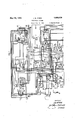
- Figure 1 shows a cord circuit and part of the commonlappa ratus associated therewith.
- Figure 2 shows the operatorsdialing circuit.
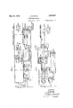
- Figure3 shows a repeated dialing trunk'circuit adapted for use with the cordfcircuit "of Figure l and Figure 4 shows a loop dialing; trunk also adapted for use with the cordvcircuit of FigureL I; l 7
- Plug 100 is' inserted in jack c300, whereupon a circuit is'established from ground; the upper high resistance winding of relay 301, sleeve of jack 300, sleeve of plug 100, conductor 101,-
- Relay-301 is energized in thiscircuit andfthrough its upper armature and front contact operates busy signale302.
- Relay 301 also placesbattery potential on conductor 303 which may .be traced through V the wind ings ofrelays 304 and 305in series.
- Belay 3.04 becomes energized, but'relay :1 jbeing marginal does not operate at this'time. 7
- Sin ce supervisory lamp 106 does not becomelightsupervisory signal 106 is in circuit with the high resistance'winding ofrelay 301, '7
- relay 30.1 to ring conductor 310.
- I V itslowermost'armature; relay 304 closes fa connection in the trunk leading from the re peating coil to the jack so that voice and tonecurrents coming in over the trunk I be transmitted tothe cord circuit.
- relay 118 is responsive to the talking key 102 it will be shown hereinafter that this relay is locked and :will he held energized under control of the common dialing key even though the individual talking key be returned tonormal.
- a talking circuit may be traced from condenser 311, winding 312 offthe trunk repeating coil, tip of jack 300, tip of plug 100, norvInal contacts ofrearringing key 122, upper outer armature and front contact of relay 118, conductor123, outermost left hand armature and back contact of relay'200, conductor 201, normal contacts of'rearsplitting key 124, upper outer armature and front contact of relay 110, conductor 125, condenser126,
- Relay 211 closes a circuit from battery, winding of relay 210, front contact and outer lower armature of relay 211, upper "outer armatureand back contact'of relay 209, contacts'212 and 2130f "front dialin'g key 203 to ground.
- Relay 210 operates in this circuit, breaking theoriginal energizing circuit for relay 211.
- Relay 210 locks up through its inner upper armature and front contact tothe'g'round originally supplied for the operation of-relay 211;
- Relay 209 operates and extends'this ground connection through its front contact and inner upper armature over the back contact and outer right hand armature of relay 205, conductor 208, front contactand innermost left hand armature of relay 200, winding of relay 200 to battery.
- This'groun'jdis also extended backover the original energizing circuit for relay 200 to the armatureof relay 115, so that now the relay 118 is held' under controlof relay 209' and frontdialing key 203. Under this condition'relay 118-willremain locked.
- relay 209 also establishes a locking circuit from ground, contacts 213 and 212 ofvfront dialing key 203, the alter-- nate contacts of therup per outer armature of relay 2 09, conductor 208, the outer right hand armature and back 'contactof relay 205, the
- This direct V 305 short circuits the winding of relay 304 which now returns to normal and'since' relay 315 has become'operated, a direct connection from conductor 306, through the upperarmature and front contact of relay 315 and'the normal contactsof the upper armature of relay 304 is established to conductor 310.
- the pulsing circuit may betraced'from battery,
- Relay 314 becomes operated 'in' this circuit and locks 'to ground through; its front contact and outer right hand armature; Relay 314 at its inner right hand armature opens thecircuit of relays 135 and 236.
- Relay 304 remains operated in series with relay 305, but relay 305 being marginal does not operate.
- relay 236 Since the circuit ofrelays 315 and 236 is opened, relay 236 becomes deenergized and after an appropriate interval relay 227 returns its armatures to normal. Since relay 227 restores, the locking circuits for, relays 224 and 209 are opened. These relays return to normal. Relay 209 iii-releasing opens the holding circuit for relay 200 and this relay releases. 7 Relay 224 in restoring opens the holding circuit lfor-relay 205 and this re-,
- the group of relays 138, 139 and 140 constitute click prevention means whereby a resistance 141 is introduced into the operators receiver circuit during the release of the dial circuit. Then the front dialing. key 203 is restored and relay 215-returns to normal, the ground forholdingrelays 138 and 139 is removed and these relaysrelease quickly.
- relay 138 opens the shunt around resistance 141 and the release of relay 139 opens the circuit for the energization of relay 140.
- Relay 140 however being slow to release does not close the'shunt about resist ance'141 for an appreciable time so that during the release of the operators] dial circuit,
- the low' resistance'winding'of relay301 is connected through the front-contact and outer left'hand armature of relay 314 to the armature of relay 317.
- Relay 317 as-indicated is polarized and responds to a reversal of current over the trunk leading from Fig. 3.
- the armature of relay 317 will rest against its'back contact sothat the low resistance winding of relay 301willnow be included inlthel circuit of the supervisory lamp 106'. If the talking'key. 102- has been lrestored to normal, then this circuit will act directly Orr-supervisory lamp 106 and cause this signal to operate. If the talking key 5102 isst'ill operated, then.
- the marginal relay 108 .willbe energiZedandsi-nce relay 200 has now been restored to normal, the low resistance 3 'mpaaae 137 will bQGOIIlBwGfiGCiIlVG, and supervisr myx lamp106 willbe operated; y I
- the trunk tip relay 401 is of relatively high resistance asco-mpared with the trunktip relay 305 which is of relatively low resistance: In,
- relay 401 series with relay 401 relay 218 w'ill note-perate, but relay 211 will remain operated-for the time being.
- j Relay 401 will operate and through the'alternate-contacts upon is opened and relay 211 willbecome'deenergized.
- relay circuit from ground, normal contactsof the of key 248 front contact andinnermost 'left j.
- relay24 6 Upon its operation relay24 6'closesacircuit from ground, front. contact" and outermost; left hand armature; of relay 246, dial pilot 7 light 226 to battery, thus'operating the dial pilot light as a-signalf to the :operat'or that she may proceed to dial.
- Relay 246i'n'inov ing its outer righthand armature closes a .circuit irom' ground, "alternate contacts of the outermost right ha-ndiarmature ofrelay .246, conductor 208, front contact and innermost left hand armature" of relay20Q to lock-8'5 this relayenergized.
- q tlon of relay 314 and the operation of th s 1 Relay 227 locks ina circuitunder control described.
- Relays 138 and 139 arev operated from ,a' ground on conductor 228 which is 7 connected through; the'irontcontactj and inof rel'ajy246 :un-
- relay 236 the circuit for relay 210 which depended on the outer left-hand armatureandfront con- 5 tact of relay 227 is opened and this relay be ⁇ comes deenergized. Thereupon a circuit is completed from ground, the alternate contacts of the outermost left hand armature of relay 246, the alternate contacts of the inner right hand armature of relay 1205, back contact and upper outer armature of relay-209, lower outer armature and back contact otrelay 211, lower armature and back contact of relay 210, front contact and middle left hand winding of relay 250 which when the interrupter 251 comesto an insulated segment is effectively placed in series with the-winding .90
- relay 217 Thereupon-re1ay250 becomes operated and places the interrupter circuit in connection withthe upper winding of relay armature of relay 246, lower normal contacts I 247, so that upon the interrupter reaching a live segment, relay 247 will become operated 7 and will lock through its lower winding.
- relay 247 becomes operated the holding circuit for relay 246- is opened and this relay restores to normal.
- relay 246 becomes deenergized,then the dial pilot light 226 becomes dark as an'indication that the dial circuit is released;
- Relay 246 opens the holding circuit for relay 200 and this relay causes the dial circuit to be dissociated from the cord circuit.
- the polarized relay411 corresponds to the V polarized relay 3l7 and performs the same 1 ice functions'in controlling the cordsupervisory 1.
- atrunk circuit a cord circuit for cooperation, with said trunk circuit, a dialing circuit associated with said cord circuit, means for locking said dialing circuit to'said cord circuit and interlocking means'in said trunk circuit for controlling said locking means.
- a cord circuit for cooperationrwith saidtrunk circuit, a dialing circuit, means for associating said" dialing circuit with said cord circult, and means in said dialing circuit and said trunk circuit constituting interlockingmeans to prevent the release of said dialingcircuit'trom saidcord circuit until said trunk.
- circuit isgprepar'ed for the release of said d1al1ng c rcuit.
- a cordcircuit for cooperation with said trunk circuit, a, dialing circuit, means'for .associatg ing said dialing circuit with said cord'circuit,
- dialing circuit for preparing for the release of said dialing circuit from said cord circuit, means responsive thereto for transmitting a signal to said trunk circuit, means in said trunk circuit responsive to said signal for transmitting a signal back to said dialing circuit and means insaid dialing circuit responsive thereto for. releaslng sa1d dialing c1rcu1t from 'sald cord circuit.
- Atrunk circuit means for establishing a path therethrough for the transmission of voice frequency currents, means for changing said path to one suiable for the transmission of signaling impulses, a cordcircuit for cooperation with said trunk circuit, a dialing circuit, means for associating saiddialing circuit with said cord circu t, 9 said means -1Il0ll1d11lg a key,
- said means 1nclud1ng a key means responsive to an operation of said key for preparing for the release of said dialing circuit from said cord circuit, means in said trunk circuit responsive to said releasing means for locking in'said first means and additional means in said dialing circuit responsive to said last means in said trunk circuit for completing the release of said cord circuit.
Description
May 24, 1932. J. B. McKIM TELEPHONE SYSTEM Filed Aug. 8, 1930 3 Sheets-Sheet 1 ka k May 24, 1932.
FIG. 2
J. B. MOKIM TELEPHONE SYSTEM Filed Aug. 8, 19:50
3 Sheets- Sheet 2 INVENTOR JBM K/M ATTORNEY May 24, 1932. J, MCKIM TELEPHONE SYSTEM Filed Aug 8, 1950 s Sheets-Sheet s no 8mm N m. at
INVENTOR J. B. M KIM BY A TTQRNEY Patented May 24, 1932 a UN TE mains BuR'roN Menu, on BROOKLYN; NEWFYORK," ASSIGNOR TO BEL magnum; LAJsoaAToams, nvconroaarnn or NEWYOB-K; n. n, A coaroaerlon OF NEW- 'YoRK,. I
TELEPHONE SYSTEM -App1icatiqn filed Au ust's, 1930. Serial No. 47379 1. 1 i
i This-invention relates to telephone systems and particularly to operator controlled the dial is. normal-signaling tones may be.
transmitted over the trunk tothe operators In accordancewith another feature of the invention a dialing circuit associated with acord circuit is lockedlto'jthe cord under controlofaimeans in the trunk whereby the re lease of the dialing circuit is preventeduntil after the trunk hasbeen put in condit on for the transmission of voice frequency currents. The drawings consist of three sheets of circuit diagram which should bevplaced Wit-ll:
FigureQ below Figure 1 and'Figures-3 and .125 4 to the right of Figure 1. Figure 1 shows a cord circuit and part of the commonlappa ratus associated therewith. Figure 2 shows the operatorsdialing circuit. Figure3 shows a repeated dialing trunk'circuit adapted for use with the cordfcircuit "of Figure l and Figure 4 shows a loop dialing; trunk also adapted for use with the cordvcircuit of FigureL I; l 7
Let it bef-assumed that aconnection is to be extended over the trunk of Fig. '3. Plug 100 is' inserted in jack c300, whereupon a circuit is'established from ground; the upper high resistance winding of relay 301, sleeve of jack 300, sleeve of plug 100, conductor 101,-
19 contacts 103' and 104 of talking key102,
conductor 105, supervisory lamp 106 to battery. Relay-301 is energized in thiscircuit andfthrough its upper armature and front contact operates busy signale302. Relay 301 also placesbattery potential on conductor 303 which may .be traced through V the wind ings ofrelays 304 and 305in series. Belay 3.04 becomes energized, but'relay :1 jbeing marginal does not operate at this'time. 7 Sin ce supervisory lamp 106 does not becomelightsupervisory signal 106 is in circuit with the high resistance'winding ofrelay 301, '7
not become lighted at this timef 7 Upon the operation of relay304 a circuit winding-3070f the trunk repeating coil,oondenser 30'8, winding 309 of thetrunk repeat 111gv c011; upper armature and front contact .is established from the tip c nductor 306, v
of relay 30.1 to ring conductor 310. Through I V itslowermost'armature; relay 304 closes fa connection in the trunk leading from the re peating coil to the jack so that voice and tonecurrents coming in over the trunk I be transmitted tothe cord circuit.
.Thefoper'ator actuates talking key Conductor 101 is now extended through con- f tacts 103 and 107 to thewindings of-:relays- .108 and '109 in series: Relay .108 is marginal and does not operatein series with the high resistance winding of relay 301, buttrela'y' 109 becomes operated in this circuit. Relay 109 throughits armature andlifront contact j" causes theenergization of relay 11'0, whereupon a circ uit'is" closed from ground, inner upper armature and front Contact "of relay 110, resistance 111, conductor 112,. contacts 113 and 1-14 of talkin g key 102, conductor 105', supervisory lamp .106 to battery, Resistance lllebeing of practically" the same value as the high resistance winding of relay 301, the
ed at this time.
Upon the operationof :a circuit is, closed from ,ground, norn1al con;
tacts of; relay 115',"contacts 116 andfllj of talking key'102, Flower winding of relay118 to'battery. Relay ll 8 abecomesenergized and w-ind-ingjof relay 115 to battery and in parallel therewith through the'windingof re come operated "in this circuitand relay 115' closes a circuit throughitsj front contact and r armatureand thence through the upper finv1'ay.121,to1battery Relays" and 121 bener (armature-and'front contact and upper?" winding of-relay 118, ,Uponitheoperationof relay115the original energlzing elrcuit for relay 1.18 is broken bu through: the continu ity' contacts of rejlay 115 theiholdin gecircuit Relay 118 is the agency cord circuit is associated with the common winding is opened.
through the upper winding of relay 118 is closed before'th'e circuit through the lower through which the apparatus shown below in Figure 1 and Figure 2. While it appears that relay 118 is responsive to the talking key 102 it will be shown hereinafter that this relay is locked and :will he held energized under control of the common dialing key even though the individual talking key be returned tonormal.
A talking circuit may be traced from condenser 311, winding 312 offthe trunk repeating coil, tip of jack 300, tip of plug 100, norvInal contacts ofrearringing key 122, upper outer armature and front contact of relay 118, conductor123, outermost left hand armature and back contact of relay'200, conductor 201, normal contacts of'rearsplitting key 124, upper outer armature and front contact of relay 110, conductor 125, condenser126,
' peating coil, lower outer armature and front windings 127 and 1280f the operators set induction coil, condenser'129, conductor 130,- front contact and nner lower armature of relay 110, lower normal contacts of rear splitting key 124, conductor 202 back contact and middle left'hand armature of relay 200, conductor 131,'front contactand inner lower armature of relay 118, ring of plug 100, ring of ack 300, winding'313 of the trunk re.-
lay 135 across the winding 128 of the operatorsset induction coil, so that tones or voice currents which may be now transmitted over the trunk will be heard by the operator.
Let it be assumed that the operator listen ing in on the trunk is assured that everything 7 is in condition for the dialing operation. Since plug 100 is connected to the front cord,
I the operator will actuate front dialing key 203. A circuitis now closed from ground, front contact and armature of relay 115, conductor 136, conductor 204,'backcontact and left hand armatureof relay 205, upper con .tacts of front dialing key 203, conductor 206,
lower outer armature and front contact of relay 110, winding of relay 200 to battery and ground. Relay 200'is operated in this circuit. Through the movement of itsright hand ar- 7 mature, relay 200 removes a ground from conductor 207 to prevent the lighting of supervisory lamp 106 through the low resistance 137; Belay 200 also, closes a circuit from-the ground connection through which it is operated to its innermost left hand armature and front contact, conductor 208, outer right hand armature and back contact of relay 205, inner upper armature and back contact of relay 209, normal contacts of the in ner upper armature of relay 210, windingsof relay 211 to battery. Relay 211 closes a circuit from battery, winding of relay 210, front contact and outer lower armature of relay 211, upper "outer armatureand back contact'of relay 209, contacts'212 and 2130f "front dialin'g key 203 to ground. Relay 210 operates in this circuit, breaking theoriginal energizing circuit for relay 211. Relay 210 locks up through its inner upper armature and front contact tothe'g'round originally supplied for the operation of-relay 211;
Since the trunk of F ig. 3 is a repeated dial: ing trunk, the marginal relay 305 will be of relatively low resistance, so that a circuit may now be traced from ground, winding of relay 305, back contact and [innermost left hand armature of relay 314, tip of jack 300, tip of plug 100, normal contacts of rear ringing key 122, upper outer armature and front con:
tact, ofrelay 118, conductor'123, outermost V left hand armature and "front contact of relay 200, conductor 222, repeating coilwinding 223, conductor 214,, normal contacts of the upper armature of relay 215, conductor- 216, upper outer armature andback contact of relay 217, front contact and inner lower armature ofrelay .211, the winding of relay H 218, winding of relay 211 to battery. Relay 211 is maintained operated in this circuit and relay 218 becomes operated; Relay- 218 becoming'energized', closes acircuit through the winding of relay'209 tobattery. Relay 209 operates and extends'this ground connection through its front contact and inner upper armature over the back contact and outer right hand armature of relay 205, conductor 208, front contactand innermost left hand armature of relay 200, winding of relay 200 to battery. This'groun'jdis :also extended backover the original energizing circuit for relay 200 to the armatureof relay 115, so that now the relay 118 is held' under controlof relay 209' and frontdialing key 203. Under this condition'relay 118-willremain locked.
and the dialing circuit will still be associated with the cord even though talking key 102 is returned to normal. I The operation of. relay 209 also establishes a locking circuit from ground, contacts 213 and 212 ofvfront dialing key 203, the alter-- nate contacts of therup per outer armature of relay 2 09, conductor 208, the outer right hand armature and back 'contactof relay 205, the
innerupper armature and front contact of relay'209, winding of relay 209' to battery.
Upon the operation of relay 209, the holding clrcuit of relay 210 which was established through the inner upper armature and back contacts of relay 209 is broken sothat relay 210 now returns'to normal. V 1 Further, upon theoperationof relay 209 a circuit is established from ground, contacts 219 and 220 of front dialing key 203, conduclay 242 tpmteaa circuit is extended from 'batteryyfront contact and'innerlower armatumor relay 242-, upper armature andfront contact of relay 215, upper outer armature and front contact ofrelay 242, front contact and outermost left handarmature ofv relay 200, conductor 123, front contact and-upper outer armature of relay 118, normal contacts of rear dialing'key 122, tip of plug 100," tip of jack 300, inner left hand "armature and back contact of'relay314, Winding of relay 305 to ground. This direct V 305 short circuits the winding of relay 304 which now returns to normal and'since' relay 315 has become'operated, a direct connection from conductor 306, through the upperarmature and front contact of relay 315 and'the normal contactsof the upper armature of relay 304 is established to conductor 310. The pulsing circuit may betraced'from battery,
frontcontact' and middle-left hand armature of relay 200, conductor 131', front contact and inner lower armature of-relay 118', ring of plug 100, ring of ack300, inner right hand 227, but this relay being slow to release does not respond and remains in its operated 'con-.
dition.
' When the dial'has returned 'to normal relays 240 and 242 will release -andsince the direct battery connect-ionto relay 305 is now broken, relay 304 will again become operated to establish the 'paththrough the trunk for tone and voice currents; In a" like manner the induction coll comprisingw1nd1ngs'223,
233, 237 and 238will becomeeifective so that V the operator may listen in on the trunk during the periods'when the dial is at normal.
When dialing is completed the dial key 223 is restored and relay 215r'eturns'to normal.
The tip lead which during the operation of relay 215 was connected through resistance 241 to battery is now connected through the {normal contacts of 'theupper armature :of relay 215, the frontcontact and outer lower armature of relay" 224, the back contact and innerlower' armature' of relay 215 to ground.
This ground connection now short circuits relay 305' and. relay 5 305 therefore releases.
f lUponthe return of relay 305 to normal, re-
'sist'ance 316 is 'conn'ected'in series with the battery connection to relay winding 'of"relay 315 which has heretofore been traced through the right hand winding of relay 236. r J
1 A circuit is now established: from ground, the lower armature and back contact of re 7 lay 305, lower armature and front contact of'relay 315, the front contact and inner lower armature of relay 'i304, winding of relay 314, upper armature and front contact of relay 301 to'battery. Relay 314 becomes operated 'in' this circuit and locks 'to ground through; its front contact and outer right hand armature; Relay 314 at its inner right hand armature opens thecircuit of relays 135 and 236. Relay 304 remains operated in series with relay 305, but relay 305 being marginal does not operate.
Since the circuit ofrelays 315 and 236 is opened, relay 236 becomes deenergized and after an appropriate interval relay 227 returns its armatures to normal. Since relay 227 restores, the locking circuits for, relays 224 and 209 are opened. These relays return to normal. Relay 209 iii-releasing opens the holding circuit for relay 200 and this relay releases. 7 Relay 224 in restoring opens the holding circuit lfor-relay 205 and this re-,
stores to normal. thus returning-all of the, relays shown in Fig. 2 to their normal condition.
The group of relays 138, 139 and 140 constitute click prevention means whereby a resistance 141 is introduced into the operators receiver circuit during the release of the dial circuit. Then the front dialing. key 203 is restored and relay 215-returns to normal, the ground forholdingrelays 138 and 139 is removed and these relaysrelease quickly. The
release of relay 138 opens the shunt around resistance 141 and the release of relay 139 opens the circuit for the energization of relay 140. Relay 140, however being slow to release does not close the'shunt about resist ance'141 for an appreciable time so that during the release of the operators] dial circuit,
the transmission eficiency of the operators set is reduced.
I After the operation of relay '314,"the low' resistance'winding'of relay301 is connected through the front-contact and outer left'hand armature of relay 314 to the armature of relay 317. Relay 317 as-indicated is polarized and responds to a reversal of current over the trunk leading from Fig. 3. Before the called subscriber answers the armature of relay 317 will rest against its'back contact sothat the low resistance winding of relay 301willnow be included inlthel circuit of the supervisory lamp 106'. If the talking'key. 102- has been lrestored to normal, then this circuit will act directly Orr-supervisory lamp 106 and cause this signal to operate. If the talking key 5102 isst'ill operated, then. the marginal relay 108 .willbe energiZedandsi-nce relay 200 has now been restored to normal, the low resistance 3 'mpaaae 137 will bQGOIIlBwGfiGCiIlVG, and supervisr myx lamp106 willbe operated; y I
When the called subscriber. answers then a reversal will take place in a mannerwell known and now thelow resistance winding I H upper armature ofrelayf247, upper, contacts of relay. 301 willbe connected throughi'the frontcontact or -relay :317, resistance 3183130 battery-"sothat signal lamp :106 Will become dark as.:an indication to the toll operator that the called subscriber has answered.
Whenever the operator restores talking key 102 to its normalcondition, relaysl l, 118 and 121 releaseand the common apparatus all becomes dissociatedfromthe cord circuit.
From the foregoing it willbe seen that as long as the dial key in the operators dialing circuit is operated that the {dial circuit is on the tip circuitcontrolled by the upper armature. of relay 215 whereby a direct ground connection is substituted for a bat tery connection through theresistance 241. This signal causes the deenergiz'ation of relay 305 in the trunk circuit.- Inresponse to this signal and when it is assured thatthe trunk is in proper condition for the transmission of voice currents, a signal will be transmitted back to the-dial circuit. This signal consists in the opening of the'circuit of relay '236 which will only-take place upon the operarelay depends on the fact ,that'relay 304has been properly operated. It is only when in response to-this signal from the trunkthat relay 236 becomes deenergized that the controlling relay 227 will be releasedto causethe restoration of the other relays in the dial circuit and 'finallythe release of relay'200.
series with relay 401 relay 218 w'ill note-perate, but relay 211 will remain operated-for the time being. j Relay 401, however, will operate and through the'alternate-contacts upon is opened and relay 211 willbecome'deenergized. A. circuit may now be traced from ground, contacts 213 and 212 of front di'a-l :l ey='-203, back contact and upper outer armature of relay 209,. lower outerarmature and back contact of relay.211,lovver;ar.- mature and front contact of relay'210, .wind
ing of relay 246 tobattery, whereupon. relay circuit from ground, normal contactsof the of key 248 front contact andinnermost 'left j.
hand armature of relay 246 :to battery.
Upon its operation relay24 6'closesacircuit from ground, front. contact" and outermost; left hand armature; of relay 246, dial pilot 7 light 226 to battery, thus'operating the dial pilot light as a-signalf to the :operat'or that she may proceed to dial. Relay 246i'n'inov ing its outer righthand armature closes a .circuit irom' ground, "alternate contacts of the outermost right ha-ndiarmature ofrelay .246, conductor 208, front contact and innermost left hand armature" of relay20Q to lock-8'5 this relayenergized. A-groundis alsoextendied from the outermost righthandarmatureof} relay 246, over conductor225 toholdrelays 115 V and 121 operated. Through its middle right g hand armature relay 246gplaces aj ground 6 on conductor 231 to causethe operation vof relay 140 in the same manner as hereinbefore nermost right hand armature becomes operated in this circuit. q tlon of relay 314 and the operation of th s 1 Relay 227 locks ina circuitunder control described. Relays 138 and 139 arev operated from ,a' ground on conductor 228 which is 7 connected through; the'irontcontactj and inof rel'ajy246 :un-
and
winding of relay227 to battery; {ZRelayf227 of relay 236 as hereinbefore describedfl 'Re- V lay-227 also closesa-circuit from ground, the alternate contacts of the outermostleft'h'and armature of relay 246, the front contact and outer j right hand 1 ar1'natur]e zof" relay' 227,
winding of relay -205to battery. Relay becoming operated locks itself ina circu itlineluding 1 its inner righthand armature and front contact to the alternate contacts of'the outermost left hand armature ofrela y 246.
control of relay 236, f 1 Relay 210 is no-w'held ground.
The original energizing circuit 1 of relay 227 5 i is nowopened andthis relayisIleiit under the Theltrunk of Fig. '4 is knownras a loop. l dialing trunk lBatteryiand ground connecftions Will-be suppliedfrom the' selectorjswitch beyond. to conductors 403 and-.404, so that a xclrcuit may now be traced fromtconductor 3 c 403,- the armature and back contact "of ringing relay 405, the back contact and upper armature of relay 406, the front:c ontact and upper armature offrelay 401,-tip of jack 400,'tip ofplug 100, normal contacts of" rear";ringing key 122, upper*outerfarmature .contacts'234 and 235, right'hand winding of relay 236, frontj contact and middle left hand armature of relay 200, conductor 131 'front contact and inner lower armatureof relay 118,"ring of plug 100' ring of jack 400, 7
*lower armature and front contact of relay 7 his 401, inner; lower armature and back contact .ot'relay406, winding of polarized relay 407, back contact and lower armature of relay 405130 conductor 404'. Current supplied from the selector'switch onlthe trunk will cause the operation-of relay'236 and at the same time hold the line relay of the selector switch operated. The current flowing in this circuit will'be-in such a direction that polarized relay 407 will not operate.
When the dial is moved 240-and 242'will become operated as hereinbefore described and the voice frequency path to the operators set will be opened at the right hand armature of relay 240,-"while the'windings 223 and 233 of the repeating coil'are short circuited bythe outer armtures of" relay 242. As the dial returns to 0 normal the pulsing contacts 234 and 235 will be intermittentlyoperated so that the selectorswitch will be stepped in a well-known V manner. 7
U When dialing has been, completed and the dial key has been restored to normal, the dialing, circuit is still held locked to the cord circuit under control of relay 407 in the trunk. When the trunk has been put in proper condition thelpolarize'd relay 407 will be oper- 'ated and a circuitestablished for relay 406. Relay 406 becomes operated and looks through. the alternate contacts of its lower outer armature to the battery supplied at theupper armature of relay 402. Relay 406, in operating, opens the tip and ring circuit of the distant selector switch and connects them tothewindings 412 and 413 ofthe trunk repeating coil, atthesam'eitime connecting the trunk repeating coil-windings 408 and 409 in circuit with the operators dialing circuit. Since a condenser 410 is now included in this circuit, relay 236 will be deenergized 'With the result that the signal now received back fromthe trunk will cause the dial circuitto be released. Since relay227 becomes 01f normal, relays signal 106.
-What'is claimed is:
deenergized upon the release; of relay 236, the circuit for relay 210 which depended on the outer left-hand armatureandfront con- 5 tact of relay 227 is opened and this relay be} comes deenergized. Thereupon a circuit is completed from ground, the alternate contacts of the outermost left hand armature of relay 246, the alternate contacts of the inner right hand armature of relay 1205, back contact and upper outer armature of relay-209, lower outer armature and back contact otrelay 211, lower armature and back contact of relay 210, front contact and middle left hand winding of relay 250 which when the interrupter 251 comesto an insulated segment is effectively placed in series with the-winding .90
of relay 217. Thereupon-re1ay250 becomes operated and places the interrupter circuit in connection withthe upper winding of relay armature of relay 246, lower normal contacts I 247, so that upon the interrupter reaching a live segment, relay 247 will become operated 7 and will lock through its lower winding. When relay 247 becomes operated the holding circuit for relay 246- is opened and this relay restores to normal. When relay 246 becomes deenergized,then the dial pilot light 226 becomes dark as an'indication that the dial circuit is released; Relay 246 opens the holding circuit for relay 200 and this relay causes the dial circuit to be dissociated from the cord circuit. I
' "The polarized relay411 corresponds to the V polarized relay 3l7 and performs the same 1 ice functions'in controlling the cordsupervisory 1. In atelephone system, atrunk circuit, a cord circuit for cooperation, with said trunk circuit, a dialing circuit associated with said cord circuit, means for locking said dialing circuit to'said cord circuit and interlocking means'in said trunk circuit for controlling said locking means.
2. In a telephone system,a trunkv circuit,
a cord circuit for cooperationrwith saidtrunk circuit, a dialing circuit, means for associating said" dialing circuit with said cord circult, and means in said dialing circuit and said trunk circuit constituting interlockingmeans to prevent the release of said dialingcircuit'trom saidcord circuit until said trunk.
circuit isgprepar'ed for the release of said d1al1ng c rcuit.
a cordcircuit for cooperation with said trunk circuit, a, dialing circuit, means'for .associatg ing said dialing circuit with said cord'circuit,
manually operable means in said dialing circuit for preparing for the release of said dialing circuit from said cord circuit, means responsive thereto for transmitting a signal to said trunk circuit, means in said trunk circuit responsive to said signal for transmitting a signal back to said dialing circuit and means insaid dialing circuit responsive thereto for. releaslng sa1d dialing c1rcu1t from 'sald cord circuit.
'4. In a telephone system, atrunk circuit, means for establishing a path therethrough for the transmission of voice frequency currents, means for changing said path to one suiable for the transmission of signaling impulses, a cordcircuit for cooperation with said trunk circuit, a dialing circuit, means for associating saiddialing circuit with said cord circu t, 9 said means -1Il0ll1d11lg a key,
means'responsive to an operation of said key a for preparing for the release of said dialing circuitfrom said cord circuit, means in said trunk circuit responsive to said releasing means for, locking'in said first means and additional means in said dialing circuit responsive to'said last means in said trunk circuit-for completing the release of said dialing circuit from said cord circuit.
5. In a telephone system, a trunk circuit,
means for establishing a path therethrough for the transmission of voice frequency cur rents, means for changing said path to one suitable for the transmision of signaling impulses, cord circuits for cooperation Withsaid trunkjcircuit, a dialing circuit common to said cord circuits, means for associating said fdialing circuit with one of said cord circuits,
said means 1nclud1ng a key, means responsive to an operation of said key for preparing for the release of said dialing circuit from said cord circuit, means in said trunk circuit responsive to said releasing means for locking in'said first means and additional means in said dialing circuit responsive to said last means in said trunk circuit for completing the release of said cord circuit. 1 i a V In Witness whereof, I hereunto subscribe my name thisfith day of August, 1930.
JAMES BURTON MOKINL'.
dialing circuit from said
Priority Applications (1)
| Application Number | Priority Date | Filing Date | Title |
|---|---|---|---|
| US473791A US1859929A (en) | 1930-08-08 | 1930-08-08 | Telephone system |
Applications Claiming Priority (1)
| Application Number | Priority Date | Filing Date | Title |
|---|---|---|---|
| US473791A US1859929A (en) | 1930-08-08 | 1930-08-08 | Telephone system |
Publications (1)
| Publication Number | Publication Date |
|---|---|
| US1859929A true US1859929A (en) | 1932-05-24 |
Family
ID=23880981
Family Applications (1)
| Application Number | Title | Priority Date | Filing Date |
|---|---|---|---|
| US473791A Expired - Lifetime US1859929A (en) | 1930-08-08 | 1930-08-08 | Telephone system |
Country Status (1)
| Country | Link |
|---|---|
| US (1) | US1859929A (en) |
-
1930
- 1930-08-08 US US473791A patent/US1859929A/en not_active Expired - Lifetime
Similar Documents
| Publication | Publication Date | Title |
|---|---|---|
| US1763893A (en) | Telephone system | |
| US1859929A (en) | Telephone system | |
| US1970337A (en) | Telephone system | |
| US1753334A (en) | Telephone system | |
| US1904252A (en) | Telephone system | |
| US1788471A (en) | Remote-control magneto-telephone system | |
| US1881669A (en) | Telephone system | |
| US2022503A (en) | Automatic telephone system | |
| US1747219A (en) | Telephone system | |
| US1882753A (en) | Telephone system | |
| US1850603A (en) | Telephone system | |
| US1844147A (en) | Automatic and semiautomatic telephone system | |
| US2173924A (en) | Telephone system | |
| US1930921A (en) | Telephone system | |
| US1831398A (en) | Telephone system | |
| US1575334A (en) | Telephone system | |
| US1364909A (en) | Telephone system | |
| US2268635A (en) | Telephone system | |
| US1580951A (en) | Telephone system | |
| US1788528A (en) | Telephone system | |
| US1463271A (en) | martin | |
| US1850608A (en) | Telephone system | |
| US1617414A (en) | Signaling system | |
| US1772690A (en) | Telephone system | |
| US1893691A (en) | Multioffice telephone system |