US185804A - Improvement in car-brakes - Google Patents
Improvement in car-brakes Download PDFInfo
- Publication number
- US185804A US185804A US185804DA US185804A US 185804 A US185804 A US 185804A US 185804D A US185804D A US 185804DA US 185804 A US185804 A US 185804A
- Authority
- US
- United States
- Prior art keywords
- brake
- car
- wheel
- brakes
- disk
- Prior art date
- Legal status (The legal status is an assumption and is not a legal conclusion. Google has not performed a legal analysis and makes no representation as to the accuracy of the status listed.)
- Expired - Lifetime
Links
- 210000000614 Ribs Anatomy 0.000 description 2
- 238000010276 construction Methods 0.000 description 2
- 239000002184 metal Substances 0.000 description 2
Images
Classifications
-
- F—MECHANICAL ENGINEERING; LIGHTING; HEATING; WEAPONS; BLASTING
- F16—ENGINEERING ELEMENTS AND UNITS; GENERAL MEASURES FOR PRODUCING AND MAINTAINING EFFECTIVE FUNCTIONING OF MACHINES OR INSTALLATIONS; THERMAL INSULATION IN GENERAL
- F16D—COUPLINGS FOR TRANSMITTING ROTATION; CLUTCHES; BRAKES
- F16D11/00—Clutches in which the members have interengaging parts
- F16D11/08—Clutches in which the members have interengaging parts actuated by moving a non-rotating part axially
- F16D11/10—Clutches in which the members have interengaging parts actuated by moving a non-rotating part axially with clutching members movable only axially
Definitions
- ATTORNEYS UNITED STATES PATENT are JOHN G. WANDS, OF NASHVILLE, TENNESSEE.
- Figure 1 of the drawings is a representation of an end view of a car, showing my brake applied.
- Fig. 2 is a central vertical sectional view of the same.
- Fig. 3 is a bottom view of the upper disk.
- the object of this invention is to prevent too much resistance from being applied to the wheels of railway-cars in braking the same. This object is accomplished by interposing between the brake-wheel and the brake certain devices adapted to yield when the strain exceeds a given amount or degree.
- A designates the end of a freight-car
- B a brake-shaft, secured to the same in a vertical position by brackets b b.
- O designates a brake-chain, attached to said brake-shaft near its bottom, in the usual manner; and D, a crank-wheel or brake-wheel, arranged loosely upon the said brake-shaft, near the upper end thereof.
- the said upper end of said shaft is capped by a washer, E, and nut F; and between said washer and said brake-wheel D is arranged a spiral expansion-spring, G, which operates to force downward said brake-wheel.
- a metal disk, H which is concave on its lower face, and ribbed or corrugated radially, as shown in detail in Fig. 3.
- a similar convex disk, I just below said concave disk, is clamped a similar convex disk, I, likewise ribbed or corrugated, and adapted to engage with said upper disk when spring G forces the same downward.
- the ribs or corrugations on disks H and I are marked h in the drawings.
- a turning-shaft provided with means for operating the same, and intermediate connections, substantially as described, whereby the devices cease to operate to increase the tension when the strain upon the brake is excessive.
- a car-brake shaft provided with a fixed friction-disk, in combination with a sliding friction-disk attached to the brake-wheel, substantially as set forth.
Description
:. c. WANDS.
CAR-BRAKE.
Patented Dec. 26, 1876.
6 Foe WITNESSES I 1/7 /E' H I INVENTOR @FMM/ Q. W617. MJ7'&,WM.
ATTORNEYS UNITED STATES PATENT are JOHN G. WANDS, OF NASHVILLE, TENNESSEE.
IMPROVEMENT IN CAR-BRAKES.
Specification forming part of Letters Patent No. 185,804, dated December 26, 1876; application filed December 2, 1876.
To all whom at may concern Be it known that I, JOHN (J. WANDS, of Nashville, in the county of Davidson and State of Tennessee, have invented a new and vall able Improvement in Freight-Oar Brakes; and I do hereby declare that the following is a full, clear, and exact description of the construction and operation of the same, reference being had to the annexed drawings, making a part of this specification, and to the letters and figures of reference marked thereon.
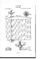
Figure 1 of the drawings is a representation of an end view of a car, showing my brake applied. Fig. 2 is a central vertical sectional view of the same. Fig. 3 is a bottom view of the upper disk.
The object of this invention is to prevent too much resistance from being applied to the wheels of railway-cars in braking the same. This object is accomplished by interposing between the brake-wheel and the brake certain devices adapted to yield when the strain exceeds a given amount or degree.
' In the annexed drawing, A designates the end of a freight-car, and B a brake-shaft, secured to the same in a vertical position by brackets b b. O designates a brake-chain, attached to said brake-shaft near its bottom, in the usual manner; and D, a crank-wheel or brake-wheel, arranged loosely upon the said brake-shaft, near the upper end thereof. The said upper end of said shaft is capped by a washer, E, and nut F; and between said washer and said brake-wheel D is arranged a spiral expansion-spring, G, which operates to force downward said brake-wheel. To said brake-wheel D on its under side, is secured a metal disk, H, which is concave on its lower face, and ribbed or corrugated radially, as shown in detail in Fig. 3. On brake-shaft B, just below said concave disk, is clamped a similar convex disk, I, likewise ribbed or corrugated, and adapted to engage with said upper disk when spring G forces the same downward. The ribs or corrugations on disks H and I are marked h in the drawings.
The operation of the devices above described is as follows: When the brake-wheel D is turned, the shat'tB turns with it until the strain of the brakes upon chain (J is sut'ficient to overcome the friction between disks H and I and the pressure of spring G, when the said brake-wheel turns independently of the said shaft, disk H passing over disk I without turning it.
I do not desire to confine myself to the devices shown, as they may be modified in various Ways without departing from the spirit of my invention, which includes a device whereby a brakeshaft ceases to rotate when the strain upon the brakes has reached a certain point or degree. In the devices shown that degree is determined by the amount of resisting power in spring G.
What I claim as new, and desire to secure by Letters Patent, is
1. In a car-brake, a turning-shaft provided with means for operating the same, and intermediate connections, substantially as described, whereby the devices cease to operate to increase the tension when the strain upon the brake is excessive.
2. A car-brake shaft provided with a fixed friction-disk, in combination with a sliding friction-disk attached to the brake-wheel, substantially as set forth.
3. The combination of brake-shaft B, spring G, wheel 0, and two friction-disks, substantially as set forth.
4. The combination of concave ribbed or corrugated disk H, attached to brake-wheel O, with convex ribbed or corrugated disk I, fixed on shaft B, and with spring G, substantially as set forth.
In testimony that I claim the above I have hereunto subscribed my name in the presence of two witnesses.
JOHN G. WANDS. Witnesses:
A. G. N ORVEL'I, J no. P. HICKMAN.
Publications (1)
| Publication Number | Publication Date |
|---|---|
| US185804A true US185804A (en) | 1876-12-26 |
Family
ID=2255211
Family Applications (1)
| Application Number | Title | Priority Date | Filing Date |
|---|---|---|---|
| US185804D Expired - Lifetime US185804A (en) | Improvement in car-brakes |
Country Status (1)
| Country | Link |
|---|---|
| US (1) | US185804A (en) |
Cited By (1)
| Publication number | Priority date | Publication date | Assignee | Title |
|---|---|---|---|---|
| US3082535A (en) * | 1959-04-20 | 1963-03-26 | Cardinell Products | Counterbalance for drawing board straightedge |
-
0
- US US185804D patent/US185804A/en not_active Expired - Lifetime
Cited By (1)
| Publication number | Priority date | Publication date | Assignee | Title |
|---|---|---|---|---|
| US3082535A (en) * | 1959-04-20 | 1963-03-26 | Cardinell Products | Counterbalance for drawing board straightedge |
Similar Documents
| Publication | Publication Date | Title |
|---|---|---|
| US185804A (en) | Improvement in car-brakes | |
| US553442A (en) | Car-brake | |
| US535867A (en) | Brake for railway-cars | |
| US118530A (en) | Improvement in wagon-brakes | |
| US795363A (en) | Brake-shaft holding and releasing device. | |
| US274144A (en) | Car-brake | |
| US301096A (en) | Car-brake | |
| US160190A (en) | Improvement in car-brakes | |
| US123003A (en) | Improvement in car-brakes | |
| US643011A (en) | Slack-adjuster. | |
| US96098A (en) | Improved railway-cab brake | |
| US363382A (en) | Car-brake | |
| US353673A (en) | Air-brake for cars | |
| US667507A (en) | Car-brake. | |
| US282714A (en) | Car-brake | |
| US100958A (en) | Improvement in automatic car-brakes | |
| US545810A (en) | Gar-brake | |
| US746613A (en) | Car-brake. | |
| US328959A (en) | John meissneb | |
| US339931A (en) | Vehicle-brake | |
| US214418A (en) | Improvement in car-brakes | |
| US532621A (en) | Brake for railway-cars | |
| US398797A (en) | phelps | |
| US119655A (en) | Improvement in wagon-brakes | |
| US606065A (en) | Emergency-brake for street-cars |