US1858032A - Filling apparatus for powdered or granular material - Google Patents
Filling apparatus for powdered or granular material Download PDFInfo
- Publication number
- US1858032A US1858032A US366127A US36612729A US1858032A US 1858032 A US1858032 A US 1858032A US 366127 A US366127 A US 366127A US 36612729 A US36612729 A US 36612729A US 1858032 A US1858032 A US 1858032A
- Authority
- US
- United States
- Prior art keywords
- disk
- filling apparatus
- secured
- pockets
- Prior art date
- Legal status (The legal status is an assumption and is not a legal conclusion. Google has not performed a legal analysis and makes no representation as to the accuracy of the status listed.)
- Expired - Lifetime
Links
Images

Classifications
-
- B—PERFORMING OPERATIONS; TRANSPORTING
- B30—PRESSES
- B30B—PRESSES IN GENERAL
- B30B15/00—Details of, or accessories for, presses; Auxiliary measures in connection with pressing
- B30B15/30—Feeding material to presses
- B30B15/302—Feeding material in particulate or plastic state to moulding presses
Definitions
- My invention relates to improvements in filling apparatus for powdered or granular material, such as are used for supplying measured amounts of dryor moist material to matrices of presses, and the object of the improvements is to provide an apparatus by means of which'exactly measured amounts of the material are supplied to the'matric'es or the like.
- my invention consists in providing a movable filF- ing member having ,one or more pockets adapted to receive the material from a supply thereof vandto carry the same to a gutter, a matrix, or the like.
- Fig. 1 is an elevation showing'a press for compressing powdered or granular material into blocks and equipped with the filling apparatus
- Fig. 2 is an elevation showing the filling apparatus separate from the press
- F ig; 3 is an elevation'looking from the left in Fig. 2, 7
- Fig. 4 is a top plan view of Fig. 2,
- Fig. 5 is a sectional elevation on an enlarged scale taken on the-line 5-5 of Fig. 4, showing the distributing member of the filling apparatus, and
- Fig. 6. is a detail plan view showing an adjustable end wall of. the pocket of the dis.- tributing member for regulating the capacity of the said pocket.
- the filling apparatus is used in connection with a press for compressing loose material into blocks, which press comprises a frame carrying a horizontal table 3 provided with a matrix 2, a plunger 4 mounted on the frame 1 for being slidable in vertical direction, a connecting rod 51a connected'to a crank 5 of a crank shaft 6, and a pulley 7 secured to the said shaft and connected with a belt gearing for operating the crank mechanism and the plunger 4.
- brackets 8 and 28 By means of brackets 8 and 28 the filling apparatus is mounted on the frame 1.
- a slightly inclined pivot bolt 10 is secured, which is formed with a collar providing a support for a ring 12 fixed in position r by means of screws 11 and having a circular base plate 13 fixed thereto.
- the pivot bolt 10 projects upwardlybeyond the ring 12, and on the upper end of the bolt and a ring 14 a distributing member 15 in the form of a circular disk is rotatably mounted.
- the ring 14 is secured to the disk 15 by means of screws 52 .or the like, and the disk is held in position on the bolt 10 by means of a washer 16 and a feather 17
- the distributing disk 15 is provided with four pockets 19 disposed in a radial manner and adapted to be moved across the plate 13,
- Eachslide 21 consists of a plate 22 shiftable between the plates 20 and a flanged portion 23 projecting downwardly from the plate 22' and having polygonal form. As appears from Fig. 2, the inner ends 24 of the slides 21 project into the space between the distributing disk 15 and the plates 20. At the parts where the pockets 19 are provided the disk 15 is provided with holes 25 through which the material is supplied to the pockets 19.
- the slides 21 can be set in different positions radially of the disk 15 for varying the capacity of the pockets,.and they are held inithe desired positions by means. of screws 26 passed through bores of the plates 20 and screwing into screw-threaded holes of the disk 15. 4 By means ofthe plate 22 the material is prevented in any position of the slides 21 from passing above the upper margin of the flange 23 and between' the plates 20, the
- the distance y isslightly. less than the dis-,4
- chute 27 Above the distributing disk 15 there is an inclined chute 27, which chute is fixed to the framel by the bracket 28. The bottom end of the chute 27 is in Contact with the rotary distributing disk 15, and. the side walls 30 of the chute 27 are continued by an annular strip 31 which is in contactwith the disk-15 and prevents the material from falling beyond the-margin of the disk.
- the stationary disk 13 on which the distributing disk 15 is rotatably mounted is provided with a cut-out portion 32 through which the material is delivered from the pockets, and below the said cut-out portion a gutter 33 is secured to the ring 12 for feeding. the said material from the pockets to the matrix 2.
- the distributing disk 15 is intermittently rotated by means of mechanism constructed as follows:
- a bearing 35 is provided in which a shaft 36' is rotatably mounted, and to the said shaft a sprocket wheel 37 is secured which is adapted to berotated by a. chain 38 from a sprocket 39 secured to the main driving shaft 6.
- a ring 41 having flat portions 40 is secured to the shaft 36, and the said ring carries arms 42 and 43, the arm 42 comprising a bolt 44 radially slidable in a bore .of the rin-g41.
- the arm 43 is equipped with two bolts 45 connected by a cross member 45aand radially slidable in bores of the ring 41.
- springs 46 and ,47 are mounted which tend to press the arms'42 and 43 outwardly, the outward movement of the said arms 42 and 43 being limited by feathers 48 and 49 normally'bearing on the flat portions 40.
- the object of the springs 46, 47 is to prevent breakage. ofparts of the driving mechanism of the disk 15when the said diskis accidentally rotated, in which case the ends of the arms 42,43 are engaged. by. the radial pins 50 and pressed inwardly thereby. If the arms 42,43-
- the operation of the filling apparatus is as follows:
- the angle 0 included between the chute. 27 and. the horizontal plane issuch that a conglomeration of the material .on the said chute is prevented. Also. the angle ,(iincludedbetween the inclined distributing disk 15 and the horizontal plane issuch that when rotating the disk.15 in.- the direction of the arrow shown in Fig. 41the material, issufliciently moved upwardly'for preventing obstruction of the material at the part indicatedsin Fig. 4 by. cross-hatching, which: conglomerati-on of the material would interfere with the regu lar supply of the'material.
- brackets 8 and 28- are-fixed to the frame 1 soas to be angularly adjustable for varying theangles cc and ,B-accordi-ngto the character of the material.
- the slides 21 are radially adjusted in the .manner described above, so that thefiange 23' thereof: shifted outwardly or inwardly, for increasing or reducing the capacity of the pocket 19.
- An apparatus for feeding measured amounts of loose material comprising a movable member having a pocket, pins secured to said member in the direction of the movement thereof one behind the other, a driving mechanism for moving said member comprising revolving arms adapted for engagement with said pins, means for supplying loose material to said pocket, and means for opening said pocket when in delivering position.
- An apparatus for feeding measured amounts of loose material comprising a movable member having a pocket, pins secured to said member in the direction of the move.- ment thereof one behind the other, a driving mechanism for moving said member comprising revolving arms elastically supported for yielding in the direction of their length and adapted for engagement with said pins, means for supplying loose material to said pocket, and means for opening said pocket when in delivering position.
- An apparatus for feeding measured amounts of loose material comprising a base plate, a distributing disc mounted on said plate for rotation, said disc being provided with a material receiving pocket open at the top and the bottom, a chute for delivering material to the face of the disk and terminating in a chamber for holding the material to be measured, said chamber being located above the disc and having communication with the pocket in the disc, said chamber enclosing the discharge end of the chute and a portion of the disc and having a wall member extending transversely across the face of the disk and into close proximity thereto, the base plate being provided with a discharge aperture beyond the confines of the chamber, and means to rotate the disc to successively move the pocket therein into the chamber for filling and over the dischargoing aperture for discharge, the transverse wall of the chamber serving to remove surplus material from the face of the disc as it emerges from said chamber.
- An apparatus for feeding measured amounts of loose material comprising a rotatable member having a pocket, radially disposed pins projecting from the periphery of said member, and driving mechanism for rotating said member including a pair of conspecification.
Description
May 10, 1932. 'BMBER 1,858,032
FILLING APPARATUS FOR POWDERED OR GRANULAR MATERIAL Filed ma 27, 1929 s Sheets-Sheet 1 Jnrenfon; 7 Heznrjzgk $277256? PM; 0 (M/m war/7gp May 10, 1932. B|MBER 1,858,032
FILLING APPARATUS FOR POWDERED OR GRANULAR MATERIA L Filed May 27, 1929 3 Sheets-Sheet 2 I .7nremforr jzezizrzck 3072567" H. BIMBER May 10, 1932.
FILLING APPARATUS FOR POWDERED OR GRANULAR MATERIAL Filed May 27, 1929 3 Sheets-Sheet 3 I I JnVepfon fi ezizrzckfizmer Patented May 10, 1932 ,NITED. STATES PATENT OFFICE HEINRICH BIMRER,- F LAUF, GERMANY, 'ASSIGNOR TO'STEATIT-MAGNESIA AKTIEN- 1 GESELLSCHAFT, 0F BERLIN-PANKOW, GERMANY, A. CORPORATION OF GERMANY FILLING APPARATUS FOR POWDEREI) OR GRAN ULAR MATERIAL Application filed May 27, 1929, fierial No. 366,127, and in Germany June 2, 1928.
My invention relates to improvements in filling apparatus for powdered or granular material, such as are used for supplying measured amounts of dryor moist material to matrices of presses, and the object of the improvements is to provide an apparatus by means of which'exactly measured amounts of the material are supplied to the'matric'es or the like. With this object in view my invention consists in providing a movable filF- ing member having ,one or more pockets adapted to receive the material from a supply thereof vandto carry the same to a gutter, a matrix, or the like. By means ofthe said movable member exactly'measured amounts of material are supplied to the said gutter or the like, and when supplying the material to the matrix of a press uniformly corn pressed'blocks are produced.
For the purpose of explaining the invention an example embodying the same has been shown in theaccompanying drawings in which the same reference characters have been used in all the views to indicate corres sponding parts. In said drawings,
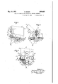
i Fig. 1 is an elevation showing'a press for compressing powdered or granular material into blocks and equipped with the filling apparatus,
Fig. 2 is an elevation showing the filling apparatus separate from the press,
F ig; 3 is an elevation'looking from the left in Fig. 2, 7
Fig. 4 is a top plan view of Fig. 2,
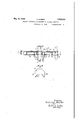
Fig. 5 is a sectional elevation on an enlarged scale taken on the-line 5-5 of Fig. 4, showing the distributing member of the filling apparatus, and
Fig. 6. is a detail plan view showing an adjustable end wall of. the pocket of the dis.- tributing member for regulating the capacity of the said pocket. I
In. the example shown in the drawings the filling apparatus is used in connection with a press for compressing loose material into blocks, which press comprises a frame carrying a horizontal table 3 provided with a matrix 2, a plunger 4 mounted on the frame 1 for being slidable in vertical direction, a connecting rod 51a connected'to a crank 5 of a crank shaft 6, and a pulley 7 secured to the said shaft and connected with a belt gearing for operating the crank mechanism and the plunger 4.
By means of brackets 8 and 28 the filling apparatus is mounted on the frame 1. To the bracket 8 a slightly inclined pivot bolt 10 is secured, which is formed with a collar providing a support for a ring 12 fixed in position r by means of screws 11 and having a circular base plate 13 fixed thereto. The pivot bolt 10 projects upwardlybeyond the ring 12, and on the upper end of the bolt and a ring 14 a distributing member 15 in the form of a circular disk is rotatably mounted. The ring 14 is secured to the disk 15 by means of screws 52 .or the like, and the disk is held in position on the bolt 10 by means of a washer 16 and a feather 17 The distributing disk 15 is provided with four pockets 19 disposed in a radial manner and adapted to be moved across the plate 13,
each being formed by angular plates 20 or rails secured to'the bottom side of the disk 15, a curved plate 18 secured to the margin of the. said disk, and a slide 21 disposed between the plates 20 and adjustable radially of the disk for regulating the capacity of the pocket.
Eachslide 21 consists of a plate 22 shiftable between the plates 20 and a flanged portion 23 projecting downwardly from the plate 22' and having polygonal form. As appears from Fig. 2, the inner ends 24 of the slides 21 project into the space between the distributing disk 15 and the plates 20. At the parts where the pockets 19 are provided the disk 15 is provided with holes 25 through which the material is supplied to the pockets 19. The slides 21 can be set in different positions radially of the disk 15 for varying the capacity of the pockets,.and they are held inithe desired positions by means. of screws 26 passed through bores of the plates 20 and screwing into screw-threaded holes of the disk 15. 4 By means ofthe plate 22 the material is prevented in any position of the slides 21 from passing above the upper margin of the flange 23 and between' the plates 20, the
said plate closing the inner part of the opening 25.
the distance y isslightly. less than the dis-,4
tance 3 Thus the pockets flare outwardly from their upper-ends downwardly.
Above the distributing disk 15 there is an inclined chute 27, which chute is fixed to the framel by the bracket 28. The bottom end of the chute 27 is in Contact with the rotary distributing disk 15, and. the side walls 30 of the chute 27 are continued by an annular strip 31 which is in contactwith the disk-15 and prevents the material from falling beyond the-margin of the disk.
The stationary disk 13 on which the distributing disk 15 is rotatably mountedis provided with a cut-out portion 32 through which the material is delivered from the pockets, and below the said cut-out portion a gutter 33 is secured to the ring 12 for feeding. the said material from the pockets to the matrix 2.
The distributing disk 15 is intermittently rotated by means of mechanism constructed as follows:
On brackets 34 secured to the frame 1 a bearing 35 is provided in which a shaft 36' is rotatably mounted, and to the said shaft a sprocket wheel 37 is secured which is adapted to berotated by a. chain 38 from a sprocket 39 secured to the main driving shaft 6. Further, a ring 41 having flat portions 40 is secured to the shaft 36, and the said ring carries arms 42 and 43, the arm 42 comprising a bolt 44 radially slidable in a bore .of the rin-g41. The arm 43 is equipped with two bolts 45 connected by a cross member 45aand radially slidable in bores of the ring 41. On the bolts 44 and 45 springs 46 and ,47 are mounted which tend to press the arms'42 and 43 outwardly, the outward movement of the said arms 42 and 43 being limited by feathers 48 and 49 normally'bearing on the flat portions 40. e
To the distributing disk 15 radial pins 50 projecting beyond the margin of the disk are secured, and when rotating the arms42, 43 by means of the chain. and sprocket, gearing 37, 38, 39, the said arms 42, 43 alternately act on the pins 50 thus imparting intermittent rotary movement to the disk 15. V
The object of the springs 46, 47 is to prevent breakage. ofparts of the driving mechanism of the disk 15when the said diskis accidentally rotated, in which case the ends of the arms 42,43 are engaged. by. the radial pins 50 and pressed inwardly thereby. If the arms 42,43-
were rigidly secured to the ring 41 the pins 50 would possibly be broken in case of such accidental movement of the disk 15, while in the construction shown in the figures the arms 42, 43 are capable of yielding against the action of the springs 46, 47, so that any injury to the mechanism is avoided.
The operation of the filling apparatus is as follows:
.iThe; loose material is, supplied; to. the. inclined-chute 27, and :it slidesudownwardly thereon and into the room 51 provided between the bottom part of thec-hute 27 and the annular strip 31. The distributing disk 15 is intermittently rotated by the arms 42, 43 engaging the pins 50, so that the pockets 19 .are successively moved through. the filling room. Thus measured amounts of the loose material are successively supplied to the pockets 19 and carried thereby upon rotation of the disk 15 to the delivery opening .32and the gutter 33, the pocket being at first closed by the base plate 13, and the lower margin 29 of the chute 27 having the functionof. stripping the excess of material from the pockets and holding the same withinthe filling space 51. I. By the rotation of the disk 15 the material placedon the surface thereof is'moved upwardly in the direction of the. arrow shown. inFig. 4, .so that any accumulation ofthe. loose material is prevented.
' When the pocket 19. arrives above: the. cutout portion 32 the loose material is delivered therefrom, and it ,slides on the gutter 33 downwardly and into the matrix 2. Therefore an exactly measured amount ofIloose material issupplied tothe matrix, so that blocks of uniform density are madeby the plunger 4.
By constructing thepockets with downwardly fiaring'side walls a complete delivery of the loose material from the pockets is insured.
The angle 0: included between the chute. 27 and. the horizontal plane issuch that a conglomeration of the material .on the said chute is prevented. Also. the angle ,(iincludedbetween the inclined distributing disk 15 and the horizontal plane issuch that when rotating the disk.15 in.- the direction of the arrow shown in Fig. 41the material, issufliciently moved upwardly'for preventing obstruction of the material at the part indicatedsin Fig. 4 by. cross-hatching, which: conglomerati-on of the material would interfere with the regu lar supply of the'material.
If desired the brackets 8 and 28- are-fixed to the frame 1 soas to be angularly adjustable for varying theangles cc and ,B-accordi-ngto the character of the material. 3
For varying theuamount of material taken by the successive; pockets 19, the slides 21 are radially adjusted in the .manner described above, so that thefiange 23' thereof: shifted outwardly or inwardly, for increasing or reducing the capacity of the pocket 19.
While in describing the invention reference has been made to a particular example embodying the same I wish it to be understood that my invention is not limited to the construction shown in the drawings, and that various changes may be made in the general arrangement of the apparatus and the construction of its parts without departing from the invention.
I claim:
1. An apparatus for feeding measured amounts of loose material, comprising a movable member having a pocket, pins secured to said member in the direction of the movement thereof one behind the other, a driving mechanism for moving said member comprising revolving arms adapted for engagement with said pins, means for supplying loose material to said pocket, and means for opening said pocket when in delivering position.
2. An apparatus for feeding measured amounts of loose material, comprising a movable member having a pocket, pins secured to said member in the direction of the move.- ment thereof one behind the other, a driving mechanism for moving said member comprising revolving arms elastically supported for yielding in the direction of their length and adapted for engagement with said pins, means for supplying loose material to said pocket, and means for opening said pocket when in delivering position.
3. An apparatus for feeding measured amounts of loose material comprising a base plate, a distributing disc mounted on said plate for rotation, said disc being provided with a material receiving pocket open at the top and the bottom, a chute for delivering material to the face of the disk and terminating in a chamber for holding the material to be measured, said chamber being located above the disc and having communication with the pocket in the disc, said chamber enclosing the discharge end of the chute and a portion of the disc and having a wall member extending transversely across the face of the disk and into close proximity thereto, the base plate being provided with a discharge aperture beyond the confines of the chamber, and means to rotate the disc to successively move the pocket therein into the chamber for filling and over the dischargoing aperture for discharge, the transverse wall of the chamber serving to remove surplus material from the face of the disc as it emerges from said chamber.
4. An apparatus for feeding measured amounts of loose material comprising a rotatable member having a pocket, radially disposed pins projecting from the periphery of said member, and driving mechanism for rotating said member including a pair of conspecification.
HEINRICH BIMBER.
Applications Claiming Priority (1)
| Application Number | Priority Date | Filing Date | Title |
|---|---|---|---|
| DE1858032X | 1928-06-02 |
Publications (1)
| Publication Number | Publication Date |
|---|---|
| US1858032A true US1858032A (en) | 1932-05-10 |
Family
ID=7746334
Family Applications (1)
| Application Number | Title | Priority Date | Filing Date |
|---|---|---|---|
| US366127A Expired - Lifetime US1858032A (en) | 1928-06-02 | 1929-05-27 | Filling apparatus for powdered or granular material |
Country Status (1)
| Country | Link |
|---|---|
| US (1) | US1858032A (en) |
-
1929
- 1929-05-27 US US366127A patent/US1858032A/en not_active Expired - Lifetime
Similar Documents
| Publication | Publication Date | Title |
|---|---|---|
| US792918A (en) | Tablet or pill counting machine. | |
| GB927320A (en) | Bearing shell orienting device | |
| GB999030A (en) | Apparatus for measurement and feeding of powdered materials | |
| GB1529635A (en) | Method and apparatus for filling vertically orientated filter beds with a particulate filter medium | |
| US1858032A (en) | Filling apparatus for powdered or granular material | |
| US1342456A (en) | Loading device | |
| US453873A (en) | Pill enumerator and bottling machine | |
| US1466835A (en) | Adjustable feeder | |
| US2634513A (en) | Drier | |
| US3225713A (en) | Material feeding device for tableting machines and the like | |
| US920597A (en) | Can-filling machine. | |
| US2799432A (en) | Depositing machine | |
| US3016572A (en) | Tabletting machines | |
| GB1102402A (en) | Improvements in or relating to silos | |
| US1295959A (en) | Feeding apparatus for weighing-machines. | |
| US839394A (en) | Lime-distributer. | |
| US2581562A (en) | Filling mechanism for automatic weighing machinery | |
| US835084A (en) | Corn-planter. | |
| US2485226A (en) | Icing comminutor and extruder | |
| US754937A (en) | Measuring and weighing mechanism. | |
| US1719788A (en) | Conveyer chute for percentage feeding machines | |
| US1188127A (en) | Dusting-machine for fruit-trees, &c. | |
| US991418A (en) | Cotton-seed culler. | |
| US1836007A (en) | Machine for molding plastic material | |
| US849003A (en) | Evaporating-pan. |