US1857733A - Apparatus for printing positive photographic pictures with continuous automatic action - Google Patents
Apparatus for printing positive photographic pictures with continuous automatic action Download PDFInfo
- Publication number
- US1857733A US1857733A US260065A US26006528A US1857733A US 1857733 A US1857733 A US 1857733A US 260065 A US260065 A US 260065A US 26006528 A US26006528 A US 26006528A US 1857733 A US1857733 A US 1857733A
- Authority
- US
- United States
- Prior art keywords
- strip
- handle
- printing
- sensitized
- platen
- Prior art date
- Legal status (The legal status is an assumption and is not a legal conclusion. Google has not performed a legal analysis and makes no representation as to the accuracy of the status listed.)
- Expired - Lifetime
Links
Images

Classifications
-
- G—PHYSICS
- G03—PHOTOGRAPHY; CINEMATOGRAPHY; ANALOGOUS TECHNIQUES USING WAVES OTHER THAN OPTICAL WAVES; ELECTROGRAPHY; HOLOGRAPHY
- G03B—APPARATUS OR ARRANGEMENTS FOR TAKING PHOTOGRAPHS OR FOR PROJECTING OR VIEWING THEM; APPARATUS OR ARRANGEMENTS EMPLOYING ANALOGOUS TECHNIQUES USING WAVES OTHER THAN OPTICAL WAVES; ACCESSORIES THEREFOR
- G03B27/00—Photographic printing apparatus
- G03B27/02—Exposure apparatus for contact printing
Definitions
- This invention relates to photographic strip printing apparatus in which the reciprocal movement of a handle at the required time feeds forward the sensitized 5 strip, operates the pressure platen and switcheson the lighting circuit necessary to effect'the exposure. It has for its object to providean improved apparatus for printing positives; provision'being made for adjustable time exposure and for making prints of difierent sizes.
- a photographic printing apparatus which includes an endless band or conveyor for feeding the strip between the platen and the source of light; such apparatus being provided with an operating handle adapted, during its forward stroke, to rotate the conveyor and feed the strip, the rearward stroke of the handle depressing the platen and completing the lighting circuit, whereby printing on the sensitized strip is effected.
- the apparatus is so arranged that the conveyor is prevented frombackward motion during the rearward stroke of the handle, so that the strip is maintained stationary during the printing operation, and the operating handle is preferably coupled to its shaft in such manner that the initial portion of the forward stroke effects release of the platen before moving the conveyor, whereby free feeding of the strip is permitted and any danger of tearing or other damage to the strip of sensitized paper is eliminated.
- the apparatus with the exception of the platen, is arranged in a casing or box which is preferably light-tight, and the operating handle is connected with the main driving shaft of the sensitized strip conveyor through an interposed free-wheel mechanism provision also being made for varying the stroke of the. handle according to the size of the print to be produced by means of stops, hereafter more fully described, which limit the traverse of the handle in the feed direction.
- Mechanically associated with the handle are a pivoted platen, situated above the sensitized" strip and brought into operation by movement of the handle, and the contact mechanism of the lighting circuit, preferably arranged on the underside of the strip in the vicinity of the lamp or other source of light; the contact mechanismbeing adjustable to provide for varying time exposures by means of the mechanism or device hereafter described.
- paratus according to one embodiment, in which:
- Figure 1 is a diagram showing the general layout of the apparatus
- Fig. 2 is a plan view of the conveyor mechanism for the sensitized strip
- Figs. 3 and 4 are views at right angles to each other of the contact mechanism of the lighting circuit
- Fig. 5 is a sectional view of a guiding device incorporating an arrangement permitting the printing of enlargements
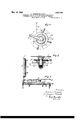
- Figs.- 6 and 7 are, respectively, a bottom plan view and an axial section of the spindleoperating handle, showing the stop mechanism associated with the operating handle and the coupling between the handle and its shaft.
- the sensitized strip A is arranged to be fed from a spool B suitably mounted in the casing of the apparatus.
- An endless conveyor comprising chains 4 and 5 that pass around sprockets 2, 7 and 3, 6 mounted on shafts 1 and3, respectively, serves to feed the strip A, the free end of which is engaged by grippers P attached to a carriage 8 that extends across or spans the conveyor chains 4 and 5; clockwise movement of the conveyor spool.
- An Operating handle-10 is arranged on the shaft 1 coaxial-1y with the sprockets 2 and 7, and has a one-way coupling with the sprocket 2 in such manner that clockwise movement of the handle produces rotation of sprocket 2, so that the conveyors 4 and 5 effect forward movement of the strip A.
- the handle-1O is free to move in a rearward or anti-clockwise direction without transmitting rotation to the sprocket 2, and the sprocket 7 is also mounted on its shaft with a one-way coupling so as to be permitted forward movement but locked against backward-rotation.
- the sprockets 3 and 6 are fixed to the shaft 3.
- the conveyors t and 5 are held stationary during the rearward movement of the handle 10, and it is during such movement that the printing on the sensitized strip takes place.
- a drum 13 n which a cab1e'13' or the like connected to the platenTwinds during the rearward movement of the handle and thus lowers the platen which is pivotally mounted and normally urged upwardly about its pivot by a spring (not shown).
- Rearward mo tion' of the handle is also adapted to close-the lighting circuitby means of a projection 15 on sprocket 2 engaging a contact member 16 so that printing on the sensitized strip A is thereby effected.
- the period of exposure is pro.- 'vided for by means of the device illustrated in detail Figs. 3 and 4.
- Such device comprises adash-pot 17 ,the cylinder of which has associateed with it the previously-mentioned contact '16, and in which slides a piston or plunger 19 secured to the frame of the device by an arm 19' that projects through said cylinder.
- K Spring 20 is interposed between the plunger and the upper wall of the cylinder 17 to ensure return of the latter to its initial position and to hold both the cylinder 17 and the contact arm or member 16 normally in elevated position.
- An air leak 18 is provided in the base of cylillustrated in Figs. 6 and 7 which permits'the inder 17 so as to permit relative .movement between the cylinder and the plunger 19.
- the apparatus in accordance with the invention includes a device feeding of varying lengths of sensitized strip under the platen. As shown in these figures, there areas'sociated with the operating bandlelO a set or series of superposed discs 11,
- Adjustment of the feed can readily be effected, in consequence, byadjustment of the position of the stop 11, so that within limits the, device can be set for tives of any desired size.
- the handle 10 In operation, the handle 10 is rotated from its initial position in a clockwise direction, and first releases the platen T from the senprinting from negasitized strip A by unwinding the cable 13' and permitting upward movement of the platen under the influence of its spring; further rotation of the handle 10 inthis direcrated in the sprocket 7, so that the sensitized strip A is locked in position during the succeeding operations.
- the carriage 8 may be supplemented or replaced by a pair of rollers 30, 31, disposed as illustrated in Fig. 1, between which rollers the sensitized strip A is said rollers being driven by the movement of the conveyor.
- the'simple platen T ill H i in Fig. 1 can be replaced by the device shown in Fig. 5, which figure also illustrates a convenient guide for the strip A.
- This guide consists of a spindle 23 provided with rightand left-hand screw threads on which are arranged two nuts 24 and 25 provided with projections or fingers 24, 25, respectively, that form guides for the said strip.
- An operating Wheel or handle 26 is provided on the end of the spindle 23 whereby the distance separating the two guide members 2 1, 25' can be varied so as to adjust the device for different Widths of sensitive paper.
- a frame I which carries pairs of slides HH, K'K which can be displaced to accommodate, and constitute a frame for, any desired size of enlarging cone, so as to permit printing of the picture required.
- the sensitized strip -With this arrangement is mountedso that its sensitized surface lies uppermost, and a suitable source of illumination is associated with the enlarging cone.
- Photographic strip-printing apparatus comprising an endless chain conveyor; means carried by said conveyor for engaging a continuous strip of sensitized material and feeding it forward through the apparatus; a
- source of light means for holding a negative 1 in position above the source of light; a movable platen adapted to press the sensitized material against the negative; an operating lever associated with the conveyor to drive the latter intermittently; and means actuated by the rearward movement of the lever for moving the platen to press the sensitized materialagainst the negative in printing position and for energizing the source of light for a predetermined printing interval.
- Apparatus as set forth in claim 1 including means for adjusting the traverse of the operating lever, whereby the strip may be fed to make prints of various sizes.
- Photographic strip-printing apparatus in which means are provided for feeding varying lengths of sensitized strip to printing position; such means embodying a set of superposed discs associated with the operating handle; a shaft about which certain of the discs are mounted for rotary adjustment; a key on said shaft; a keyway in said handle to receive the key slidably therein and limit the travel of the handle, a stop on one of the rotatable discs, and a projection on the handle to strike against the stop.
Description
May 10, 1932.
E; MANZOTTI ET AL APPARATUS FOR PRINTING POSITIVE PHOTOGRAPHIC PICTURES WITH CONTINUOUS AUTOMATIC ACTION Filed March 8, 1928 2 Sheets-Sheet l VII/I/I/ I,
IIII/I/IIJII May 10, 1932.
E. MANZQTTI ET AL APPARATUS FOR PRINTING POSITIVE PHOTOGRAPHIC PICTURES WITH CONTINUOUS AUTOMATIC ACTION Flled March 8 1928 2 Sheets-Sheet 2 .5 venfor-5.
1; a in w m; H 4 :b j M r 5 2/ m Patented May 10, 1932 UNITED STATES PATENT OFFICE APPARATUS r03 PRINTING POSITIVE PHOTOGRAPHIG rrcrunns WITH CONTINUOUS 1 AUTOMATIC ACTION Application filed March 8, 1928, Serial No. 260,065, and in. Italy April 7, 1927.
This invention relates to photographic strip printing apparatus in which the reciprocal movement of a handle at the required time feeds forward the sensitized 5 strip, operates the pressure platen and switcheson the lighting circuit necessary to effect'the exposure. It has for its object to providean improved apparatus for printing positives; provision'being made for adjustable time exposure and for making prints of difierent sizes.
In accordance with the present invention, a photographic printing apparatus is utilized which includes an endless band or conveyor for feeding the strip between the platen and the source of light; such apparatus being provided with an operating handle adapted, during its forward stroke, to rotate the conveyor and feed the strip, the rearward stroke of the handle depressing the platen and completing the lighting circuit, whereby printing on the sensitized strip is effected.
The apparatus is so arranged that the conveyor is prevented frombackward motion during the rearward stroke of the handle, so that the strip is maintained stationary during the printing operation, and the operating handle is preferably coupled to its shaft in such manner that the initial portion of the forward stroke effects release of the platen before moving the conveyor, whereby free feeding of the strip is permitted and any danger of tearing or other damage to the strip of sensitized paper is eliminated.
The apparatus, with the exception of the platen, is arranged in a casing or box which is preferably light-tight, and the operating handle is connected with the main driving shaft of the sensitized strip conveyor through an interposed free-wheel mechanism provision also being made for varying the stroke of the. handle according to the size of the print to be produced by means of stops, hereafter more fully described, which limit the traverse of the handle in the feed direction.
Mechanically associated with the handle are a pivoted platen, situated above the sensitized" strip and brought into operation by movement of the handle, and the contact mechanism of the lighting circuit, preferably arranged on the underside of the strip in the vicinity of the lamp or other source of light; the contact mechanismbeing adjustable to provide for varying time exposures by means of the mechanism or device hereafter described.
ings which illustrate, by way of example, ap-
paratus according to one embodiment, in which:
Figure 1 is a diagram showing the general layout of the apparatus;
Fig. 2 is a plan view of the conveyor mechanism for the sensitized strip;
Figs. 3 and 4 are views at right angles to each other of the contact mechanism of the lighting circuit;
Fig. 5 is a sectional view of a guiding device incorporating an arrangement permitting the printing of enlargements;
Figs.- 6 and 7 are, respectively, a bottom plan view and an axial section of the spindleoperating handle, showing the stop mechanism associated with the operating handle and the coupling between the handle and its shaft.
Referring more particularly to Figs. 1 and 2, the sensitized strip A is arranged to be fed from a spool B suitably mounted in the casing of the apparatus. An endless conveyor comprising chains 4 and 5 that pass around sprockets 2, 7 and 3, 6 mounted on shafts 1 and3, respectively, serves to feed the strip A, the free end of which is engaged by grippers P attached to a carriage 8 that extends across or spans the conveyor chains 4 and 5; clockwise movement of the conveyor spool.
efieoting withdrawal of the strip from the An Operating handle-10 is arranged on the shaft 1 coaxial-1y with the sprockets 2 and 7, and has a one-way coupling with the sprocket 2 in such manner that clockwise movement of the handle produces rotation of sprocket 2, so that the conveyors 4 and 5 effect forward movement of the strip A. The handle-1O is free to move in a rearward or anti-clockwise direction without transmitting rotation to the sprocket 2, and the sprocket 7 is also mounted on its shaft with a one-way coupling so as to be permitted forward movement but locked against backward-rotation. The sprockets 3 and 6 are fixed to the shaft 3. In this way, the conveyors t and 5 are held stationary during the rearward movement of the handle 10, and it is during such movement that the printing on the sensitized strip takes place. Associated with the handle 10 is a drum 13 n which a cab1e'13' or the like connected to the platenTwinds during the rearward movement of the handle and thus lowers the platen which is pivotally mounted and normally urged upwardly about its pivot by a spring (not shown). Rearward mo tion' of the handle is also adapted to close-the lighting circuitby means of a projection 15 on sprocket 2 engaging a contact member 16 so that printing on the sensitized strip A is thereby effected. Variationin the period of exposure is pro.- 'vided for by means of the device illustrated in detail Figs. 3 and 4. Such device comprises adash-pot 17 ,the cylinder of which has asociated with it the previously-mentioned contact '16, and in which slides a piston or plunger 19 secured to the frame of the device by an arm 19' that projects through said cylinder. K Spring 20 is interposed between the plunger and the upper wall of the cylinder 17 to ensure return of the latter to its initial position and to hold both the cylinder 17 and the contact arm or member 16 normally in elevated position.
' Completion of the-lighting circuit is actually efiected by a lever 21 which, on depression of the contact member .16, caused by its being struck by the projection 15 on rearwardmovement of the handle, contacts with an adjustable screw or stop 22 carried by the dashpot cylinder 17, adjustment of said screw Serving to vary the period of illumination and, consequently, the time of the exposure.
An air leak 18 is provided in the base of cylillustrated in Figs. 6 and 7 which permits'the inder 17 so as to permit relative .movement between the cylinder and the plunger 19.
In order to enable printing from negatives of difierent dimensions, the apparatus in accordance with the invention includes a device feeding of varying lengths of sensitized strip under the platen. As shown in these figures, there areas'sociated with the operating bandlelO a set or series of superposed discs 11,
filfldlil, delslilgned to gmit the travel of the an e 10 w 'ch hasa e a 10 engagin a key 1 on the shaft 1. W y g 1 The upper and middle discs 11 and 11' are designed for rotary adjustment about the shaft 1, a stop 11 being provided on the disc 11 and serving as an abutment for a projection or tooth 12 associated with the operatin handle 10. This stop 11 is set in the desired position according to the size of the negative to be printed by means of handles or like projections 11 provided on the top disc 11; and to ensure correct adjustment of the stop 11, the bottom disc 11", which is fixed, is preferably provided with a graduated scale, suitable means (not shown) being provided for maintaining the discs 11, 11 in their adjusted position. V a
Adjustment of the feed can readily be effected, in consequence, byadjustment of the position of the stop 11, so that within limits the, device can be set for tives of any desired size.
In operation, the handle 10 is rotated from its initial position in a clockwise direction, and first releases the platen T from the senprinting from negasitized strip A by unwinding the cable 13' and permitting upward movement of the platen under the influence of its spring; further rotation of the handle 10 inthis direcrated in the sprocket 7, so that the sensitized strip A is locked in position during the succeeding operations.
7 Continued rearward rotation of the handle I 10 eifects depression of the platen Tby means of the cable 13' winding on the drum 13, and
subsequently closes the lighting circuit when theprOjection-or tooth 15 the contact member 16; the period ofillumination and, consequently, of exposure being variable at the will of the operator as before described in connection with Figs. 3 and 4, and completion of the rearward travel of the handle 10 leaving the cylinder 17 free to return to its normal position with the circuit broken.
If desired, the carriage 8 may be supplemented or replaced by a pair of rollers 30, 31, disposed as illustrated in Fig. 1, between which rollers the sensitized strip A is said rollers being driven by the movement of the conveyor.
Where it is desired to provide for prin enlargements, the'simple platen T ill H i in Fig. 1 can be replaced by the device shown in Fig. 5, which figure also illustrates a convenient guide for the strip A. This guide consists of a spindle 23 provided with rightand left-hand screw threads on which are arranged two nuts 24 and 25 provided with projections or fingers 24, 25, respectively, that form guides for the said strip. An operating Wheel or handle 26 is provided on the end of the spindle 23 whereby the distance separating the two guide members 2 1, 25' can be varied so as to adjust the device for different Widths of sensitive paper.
Referring now to the arrangement illustrated in Fig. 5, in place of the ordinary platen T before described a frame I is provided which carries pairs of slides HH, K'K which can be displaced to accommodate, and constitute a frame for, any desired size of enlarging cone, so as to permit printing of the picture required. The sensitized strip -With this arrangement is mountedso that its sensitized surface lies uppermost, and a suitable source of illumination is associated with the enlarging cone.
It will be understood that the devices i1- lustrated are shown diagrammatically by way of example, and that modifications can be included without departing from the spirit and scope of the invention,for instance any suitable lighting system can be employed, although a system including a pneumatic-brake as illustrated is preferred.
We claim as our invention:
1. Photographic strip-printing apparatus, comprising an endless chain conveyor; means carried by said conveyor for engaging a continuous strip of sensitized material and feeding it forward through the apparatus; a
source of light; means for holding a negative 1 in position above the source of light; a movable platen adapted to press the sensitized material against the negative; an operating lever associated with the conveyor to drive the latter intermittently; and means actuated by the rearward movement of the lever for moving the platen to press the sensitized materialagainst the negative in printing position and for energizing the source of light for a predetermined printing interval.
2. Apparatus as set forth in claim 1, including means actuated by the forward stroke of the lever for releasing the platen before the lever moves the conveyor. so as to permit free feeding of the sensitized strip.
3. Apparatus as set forth in claim 1, including means for adjusting the printing interval.
4. Apparatus as set forth in claim 1, including means for adjusting the printing interval, said means comprising a pneumatic dash-pot.
5. Apparatus as set forth in claim 1, including means for adjusting the traverse of the operating lever, whereby the strip may be fed to make prints of various sizes.
6. Apparatus as set forth in claim 1, including an adjustable stop to limit the movement of the operating lever.
7. Apparatus as set forth in claim 1, including adjustable means for feedin various widths of sensitized strip materia.
8. Photographic strip-printing apparatus, according to claim 1, in which means are provided for feeding varying lengths of sensitized strip to printing position; such means embodying a set of superposed discs associated with the operating handle; a shaft about which certain of the discs are mounted for rotary adjustment; a key on said shaft; a keyway in said handle to receive the key slidably therein and limit the travel of the handle, a stop on one of the rotatable discs, and a projection on the handle to strike against the stop.
In testimony whereof we afiix our signatures.
ERMINIO MANZOTTI. EUGENIO MANZOTTI.
Applications Claiming Priority (1)
| Application Number | Priority Date | Filing Date | Title |
|---|---|---|---|
| IT1857733X | 1927-04-07 |
Publications (1)
| Publication Number | Publication Date |
|---|---|
| US1857733A true US1857733A (en) | 1932-05-10 |
Family
ID=11434748
Family Applications (1)
| Application Number | Title | Priority Date | Filing Date |
|---|---|---|---|
| US260065A Expired - Lifetime US1857733A (en) | 1927-04-07 | 1928-03-08 | Apparatus for printing positive photographic pictures with continuous automatic action |
Country Status (1)
| Country | Link |
|---|---|
| US (1) | US1857733A (en) |
Cited By (1)
| Publication number | Priority date | Publication date | Assignee | Title |
|---|---|---|---|---|
| US2780154A (en) * | 1952-04-16 | 1957-02-05 | Musho Peter | Photographic printing machine |
-
1928
- 1928-03-08 US US260065A patent/US1857733A/en not_active Expired - Lifetime
Cited By (1)
| Publication number | Priority date | Publication date | Assignee | Title |
|---|---|---|---|---|
| US2780154A (en) * | 1952-04-16 | 1957-02-05 | Musho Peter | Photographic printing machine |
Similar Documents
| Publication | Publication Date | Title |
|---|---|---|
| US2968992A (en) | Camera apparatus and method of making up printed copy | |
| US1857733A (en) | Apparatus for printing positive photographic pictures with continuous automatic action | |
| US2019260A (en) | Photographic printing machine | |
| US2401203A (en) | Material separating and delivery means | |
| US2891443A (en) | Photographic color printer | |
| US1204098A (en) | Photographic duplicating and enlarging apparatus. | |
| US2649018A (en) | Control mechanism for photographic copying apparatus | |
| US1970381A (en) | Photographic copy holding apparatus | |
| US3432236A (en) | Photoprinting apparatus | |
| US3138374A (en) | Pick-up and separating apparatus | |
| US2015803A (en) | Photographic copying machine | |
| US3221855A (en) | Single revolution clutch mechanism | |
| US2033290A (en) | Photographic copying machine | |
| GB1147001A (en) | Photographic projection printers | |
| US2001597A (en) | Camera | |
| US2738704A (en) | Strip material advancing mechanism | |
| US2394817A (en) | Photographic printer | |
| US2646731A (en) | Photocomposing apparatus | |
| US3266405A (en) | Photographic apparatus | |
| US3161121A (en) | Process and apparatus for the manufacture of photoprints from composed translucent laminar originals | |
| US3846022A (en) | Optical printer | |
| US3121381A (en) | Photocopy exposure machine | |
| US1806762A (en) | Photographino apparatus | |
| US3237514A (en) | Machine for photographically reproducing data | |
| US3615133A (en) | Photocopy apparatus |