US185758A - Improvement in padlocks - Google Patents
Improvement in padlocks Download PDFInfo
- Publication number
- US185758A US185758A US185758DA US185758A US 185758 A US185758 A US 185758A US 185758D A US185758D A US 185758DA US 185758 A US185758 A US 185758A
- Authority
- US
- United States
- Prior art keywords
- tumblers
- roller
- hasp
- dog
- seat
- Prior art date
- Legal status (The legal status is an assumption and is not a legal conclusion. Google has not performed a legal analysis and makes no representation as to the accuracy of the status listed.)
- Expired - Lifetime
Links
- 210000000474 Heel Anatomy 0.000 description 18
- 210000000214 Mouth Anatomy 0.000 description 12
- 239000002184 metal Substances 0.000 description 6
- 238000010276 construction Methods 0.000 description 4
- 210000004874 lower jaw Anatomy 0.000 description 4
- 230000036633 rest Effects 0.000 description 4
- 239000011230 binding agent Substances 0.000 description 2
- 230000005484 gravity Effects 0.000 description 2
- 230000004301 light adaptation Effects 0.000 description 2
- 238000000034 method Methods 0.000 description 2
- 238000005192 partition Methods 0.000 description 2
- 230000000284 resting Effects 0.000 description 2
Images

Classifications
-
- E—FIXED CONSTRUCTIONS
- E05—LOCKS; KEYS; WINDOW OR DOOR FITTINGS; SAFES
- E05B—LOCKS; ACCESSORIES THEREFOR; HANDCUFFS
- E05B67/00—Padlocks; Details thereof
- E05B67/06—Shackles; Arrangement of the shackle
- E05B67/08—Padlocks with shackles hinged on the case
- E05B67/14—Padlocks with shackles hinged on the case with devices for securing the hinged end of the shackle
-
- Y—GENERAL TAGGING OF NEW TECHNOLOGICAL DEVELOPMENTS; GENERAL TAGGING OF CROSS-SECTIONAL TECHNOLOGIES SPANNING OVER SEVERAL SECTIONS OF THE IPC; TECHNICAL SUBJECTS COVERED BY FORMER USPC CROSS-REFERENCE ART COLLECTIONS [XRACs] AND DIGESTS
- Y10—TECHNICAL SUBJECTS COVERED BY FORMER USPC
- Y10T—TECHNICAL SUBJECTS COVERED BY FORMER US CLASSIFICATION
- Y10T70/00—Locks
- Y10T70/40—Portable
- Y10T70/413—Padlocks
- Y10T70/437—Key-controlled
- Y10T70/446—Rigid shackle
- Y10T70/465—Pivoted
- Y10T70/474—Swinging detent
- Y10T70/478—Pivoted end only engaged
-
- Y—GENERAL TAGGING OF NEW TECHNOLOGICAL DEVELOPMENTS; GENERAL TAGGING OF CROSS-SECTIONAL TECHNOLOGIES SPANNING OVER SEVERAL SECTIONS OF THE IPC; TECHNICAL SUBJECTS COVERED BY FORMER USPC CROSS-REFERENCE ART COLLECTIONS [XRACs] AND DIGESTS
- Y10—TECHNICAL SUBJECTS COVERED BY FORMER USPC
- Y10T—TECHNICAL SUBJECTS COVERED BY FORMER US CLASSIFICATION
- Y10T70/00—Locks
- Y10T70/70—Operating mechanism
- Y10T70/7441—Key
- Y10T70/7757—Push or pull key operation
Definitions
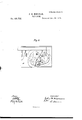
- Figure l is a plan view 01' a circular padlock with the upper outer shell removed, showing the parts in position when the device is locked. The dotted lines indicate the movement of the tumblers and independent roller in unlocking.
- Fig. 2 is a like view, showing the parts in position when the device is unlocked.
- Fig. 3 is a central section through the tumblers and key-hole, showing chamber or seat formed by the recesses in the tumblers and the independent roller therein.
- Figs. 4, 5, 6, and 7 show the different forms of the tumblers (with the springs attached) now used to illustrate the invention.
- Fig.8 IS a plan view of the invention applied to a door-lock.
- This invention relates to improvements in locks; and it consists more particularly, first, in so constructing and arranging the several parts of the lock, that when locked the hasp or shackle and dog are completely disconnected from the tumblers, and can only be acted upon and unlocked by the interposition of an independent roller 5 second, in a series of tumblers or movable pieces each having a portion of the interior cut away, the said openings thus formed uniting when the several tumblers are placed in position upon each other, to form a cavity, recess, or chamber in which the aforesaid roller rests when the device is locked, and from which it is adapted to fall by gravity when the device is being unlocked; third, in a guard plate or partition extending from the upper to the under plate of the lock-case, and interposed between the tumbler legs or projections and body of the tumblers, and serving to prevent any tampering with the interior part of the lock; fourth, in the combination, with the series of tumblers adapted to form, by their peculiar construction and
- A denotes the hasp or shackle suitably pivoted in the case B.
- the projection oi its heel is a concavity, a, in the form of an arc of a circle, adapted to fit o er the projection c on the pivoted dog (J, which projection has a convexity in form of an arc of a circle of like radius with the circle aforesaid.
- This pivoted dog 0 is kept steadily in place by a spring, D, which presses against the spur c of the dog, and in this position the arm 11 of said dog projects horizontally over a space at the mouth of the seat or chamber (to be presently described) formed in the tumblers E E.
- a spring, D which presses against the spur c of the dog
- the arm 11 of said dog projects horizontally over a space at the mouth of the seat or chamber (to be presently described) formed in the tumblers E E.
- There may be two or more of these tumblers though in my present device, illustrating the invention, I have shown five.
- These tumblers are arranged and pivoted in the case at any desirable point, so as to have suit able play during the process of locking and unlocking the device. Each one has on one side, now shown at the lower side, a leg or projection, e, of like shape and size, and projecting at a small angle from the tumbler.
- a fixed guardplate, F projects into the spaces or angles between the said legs and tumblers, and serves to limit the upward and downward movement of the tumblers and legs, because in said movement the one or the other strikes upon the upper or under side of said plate F.
- This plate is wide enough to extend from the upper to the under plates of the lock-case, and may be affixed to another plate set at right angles to it, the upper edge thereof constitut ing the stay of the dog in its down move ment in looking the device, and the inner face toward the tumblers, making the bounds for the movement of the independent roller G as it falls from its seat orchamber in thetumblers, as will presently be explained; or, instead of two plates for this purpose, a single piece of metal, suitably bent, will answer for the same purpose.
- the several tumblers E are made of thin pieces of metal stamped or cut out, each having a hole in one end, through which the pivot passes, the leg or projection e atbrementioned, the opening (1, and the mouth or opening fin the front edge. Excepting in the position of this openingf, these tumblers E are nearly alike. Ordinarily a single die can be used to stamp them out, the shape and contour of the said opening f being afterward fashioned by hand or by suitable tools.
- the opening (1 in each tumbler is made oblong, the front wall or boundary of said opening 01 being cut away sufliciently to form a mouth for the passage in or out of the independent and movable roller G; but this mouthfis not in the same place in each tumbler.
- guard-tumbler now shown as the central tumbler, and marked E, which has simply an opening, f, in :ts edge, of about the same size as the months in the tumblers E.
- Its lower jaw g serves as a guide to conduct the roller G into the mouths f of said openings 01 when the proper key has placed them in a position to receive it.
- guardtumbler In some instances it may be found advantageous to apply and use more than one guardtumbler; but any such adaptation would be merely the counterpart of what I have already described.
- the springs E all of which, excepting the guard-tumbler spring E have their ends extending up and resting against a projection, h, of the heel of the hasp, and serve to actuate the tumbler, and also to throw out the hasp.
- the end of spring E of the guardtumbler rests against the side of the case or look; but this arrangement is a mere matter of mechanical skill, and may be varied to suit convenience.
- an arm, A To the projection h of the heel of the hasp or shackle is attached an arm, A, the use and oflice of which are to return the roller G to its seat or chamber after the operation of unlocking the device has been performed.
- the key is usually a flat piece of metal with its upper end or edge, as the case may be, serrated or indented to correspond with the tumblers, and adapted to be fitted in key-hole I, and cause such movement of the tumblers as will bring the mouths f of the several openings d in line with each other, and open a passage to the seat or chamber formed as aforesaid by said openings (1.
- This lock may be of any suitable shape or form, square, oblong, round, or elliptical. In some of these, as shown in Fig. 8, it may be necessary to adjust the bolt to the hasp or shackle; but all this is mere detail of construction, and falls within the province of the workman in constructing the device above described.
- the roller G may be in shape cylindrical, or a ball or sphere.
- the tumbler In combination with the guard-plate F, extending from the upper to the under plate of the lock-case, the tumbler having legs or projections, substantially as described.
- roller G In combination with the dog, the roller G, adapted to operate in connection therewith and with the tumblers, substantially as described.
Description
ZSheets-Sh t 1 I. H. KINSMAN.
PAD-LOCK. Patented Dec. 26, 1875 TH E GRAPHIC COMY 2 Sheets-Sheet 2. J. H. KINSMAN.
PAD-LOCK. No.185,758. Patented Dec.26, 1876.
flied Inventor W Man v xmw.
TH E GRAPHIC EILNY UNITED STATES PATENT OEETGE.
JOHN H. KINSMAN, OF SALEM, MASSACHUSETTS.
IMPROVEMENT IN PADLOCKS.
Specification forming part of Letters Patent No. 185,758, dated December 26, 1876; application filed May 24, 187
To all whom it may concern:
Be it known that I, JOHN H. KINSMAN, of Salem, in the county of Essex and State of Massachusetts, have invented certain new and useful Improvements in Locks and I do hereby declare that the following is a full, clear, and exact description thereof, which will enable others skilled in the art to which it pertains to make and use the same, reference being had to the accompanying drawings, and to the letters of reference marked thereon, which form a part of this specification.
Figure l is a plan view 01' a circular padlock with the upper outer shell removed, showing the parts in position when the device is locked. The dotted lines indicate the movement of the tumblers and independent roller in unlocking. Fig. 2 is a like view, showing the parts in position when the device is unlocked. Fig. 3 is a central section through the tumblers and key-hole, showing chamber or seat formed by the recesses in the tumblers and the independent roller therein. Figs. 4, 5, 6, and 7 show the different forms of the tumblers (with the springs attached) now used to illustrate the invention. Fig.8 IS a plan view of the invention applied to a door-lock.
This invention relates to improvements in locks; and it consists more particularly, first, in so constructing and arranging the several parts of the lock, that when locked the hasp or shackle and dog are completely disconnected from the tumblers, and can only be acted upon and unlocked by the interposition of an independent roller 5 second, in a series of tumblers or movable pieces each having a portion of the interior cut away, the said openings thus formed uniting when the several tumblers are placed in position upon each other, to form a cavity, recess, or chamber in which the aforesaid roller rests when the device is locked, and from which it is adapted to fall by gravity when the device is being unlocked; third, in a guard plate or partition extending from the upper to the under plate of the lock-case, and interposed between the tumbler legs or projections and body of the tumblers, and serving to prevent any tampering with the interior part of the lock; fourth, in the combination, with the series of tumblers adapted to form, by their peculiar construction and arrangement, a cavity or recess, a roller in such a manner that it can only be released from the cavity or recess by the operation of the proper key in the right position upon the legs or projections of the tumblers; fifth, in the combination, with the heel of the hasp or shackle, of an arm adapted to automatically restore the roller to position in the recesses of the tumblers whenever the device is unlocked; sixth, in the combination of the tumblers, having suitable springs, and adapted to provide in certain positions a suitable seat or recess with the roller and hasp or bolt heel-spring and connecting mechanism-all as will now be more specifically and in detail set out and explained.
In the drawings, A denotes the hasp or shackle suitably pivoted in the case B. In the projection oi its heel is a concavity, a, in the form of an arc of a circle, adapted to fit o er the projection c on the pivoted dog (J, which projection has a convexity in form of an arc of a circle of like radius with the circle aforesaid. By means of the exact correspondence in shape and size, when the device is locked the conxevity c smoothly and closely fits into the concavity a, and forms a firm stay and binder to the heel of the hasp or shackle, so that the same cannot be moved. This pivoted dog 0 is kept steadily in place by a spring, D, which presses against the spur c of the dog, and in this position the arm 11 of said dog projects horizontally over a space at the mouth of the seat or chamber (to be presently described) formed in the tumblers E E. There may be two or more of these tumblers, though in my present device, illustrating the invention, I have shown five. These tumblers are arranged and pivoted in the case at any desirable point, so as to have suit able play during the process of locking and unlocking the device. Each one has on one side, now shown at the lower side, a leg or projection, e, of like shape and size, and projecting at a small angle from the tumbler.
As placed in the lock case a fixed guardplate, F, projects into the spaces or angles between the said legs and tumblers, and serves to limit the upward and downward movement of the tumblers and legs, because in said movement the one or the other strikes upon the upper or under side of said plate F. This plate is wide enough to extend from the upper to the under plates of the lock-case, and may be affixed to another plate set at right angles to it, the upper edge thereof constitut ing the stay of the dog in its down move ment in looking the device, and the inner face toward the tumblers, making the bounds for the movement of the independent roller G as it falls from its seat orchamber in thetumblers, as will presently be explained; or, instead of two plates for this purpose, a single piece of metal, suitably bent, will answer for the same purpose.
The several tumblers E are made of thin pieces of metal stamped or cut out, each having a hole in one end, through which the pivot passes, the leg or projection e atbrementioned, the opening (1, and the mouth or opening fin the front edge. Excepting in the position of this openingf, these tumblers E are nearly alike. Ordinarily a single die can be used to stamp them out, the shape and contour of the said opening f being afterward fashioned by hand or by suitable tools.
Generally the opening (1 in each tumbler is made oblong, the front wall or boundary of said opening 01 being cut away sufliciently to form a mouth for the passage in or out of the independent and movable roller G; but this mouthfis not in the same place in each tumbler.
In addition to the regular tumblers E, there is also a guard-tumbler, now shown as the central tumbler, and marked E, which has simply an opening, f, in :ts edge, of about the same size as the months in the tumblers E. Its lower jaw g serves as a guide to conduct the roller G into the mouths f of said openings 01 when the proper key has placed them in a position to receive it.
In some instances it may be found advantageous to apply and use more than one guardtumbler; but any such adaptation would be merely the counterpart of what I have already described.
When the several tumblers are placed the one upon the other, the legs and pivot apertures of all will coincide, while the openings (1 serve to make a seat or chamber of suflicient size to contain the roller G when the device is locked, while the uncut portions of the tront edges form fingers or guards, which hold said roller in place.
To the rear edges of the tumblers are afiixed the springs E all of which, excepting the guard-tumbler spring E have their ends extending up and resting against a projection, h, of the heel of the hasp, and serve to actuate the tumbler, and also to throw out the hasp. The end of spring E of the guardtumbler rests against the side of the case or look; but this arrangement is a mere matter of mechanical skill, and may be varied to suit convenience.
To the projection h of the heel of the hasp or shackle is attached an arm, A, the use and oflice of which are to return the roller G to its seat or chamber after the operation of unlocking the device has been performed. The key is usually a flat piece of metal with its upper end or edge, as the case may be, serrated or indented to correspond with the tumblers, and adapted to be fitted in key-hole I, and cause such movement of the tumblers as will bring the mouths f of the several openings d in line with each other, and open a passage to the seat or chamber formed as aforesaid by said openings (1. This lock may be of any suitable shape or form, square, oblong, round, or elliptical. In some of these, as shown in Fig. 8, it may be necessary to adjust the bolt to the hasp or shackle; but all this is mere detail of construction, and falls within the province of the workman in constructing the device above described.
As thus made, combined, and arranged, the operation of my said device will be readily understood. When the device is locked the roller G is held in its seat or chamber by the uncut portions of the front edges of said tumblers. The key being inserted and pressed upward or turned while the lock is held or fixed edgewise, the mouths f being downward or on the under side of said seat or chamber, the months will so coincide as to form a passage through which the said roller G falls, and it then comes against the inner face of the guard-plate F; then, by the continued motion of the key upon the tumblers, the upper edges of the lowerjaws g of the tumblers, impinging upon said roller, cause it to press against the projecting arms I) of the dog 0 until said dog rises far enough to release the convexity e from its seat in the concavity a on the heel of the hasp or shackle. At this moment the tumbler-springs E, operating on the projection h of said heel, throw back the hasp. In this movement of the heel the arm A has returned the said roller G to its seat.
The roller G may be in shape cylindrical, or a ball or sphere.
Having thus described my invention, what I consider new, and desire to secure by Letters Patent, is
1. The combination and arrangement of the hasp or shackle, the dog, the roller, and the tumblers, whereby when the device is locked the hasp or shackle and the dog are completely disconnected from the tumblers, substantially as described.
2. The combination of the tumblers, each having an opening, d, with the roller G, said openings forming a seat or chamber for the reception of the roller, substantially as and for the purposes set forth.
3. In combination with the guard-plate F, extending from the upper to the under plate of the lock-case, the tumbler having legs or projections, substantially as described.
4. In combination with the dog, the roller G, adapted to operate in connection therewith and with the tumblers, substantially as described.
5. The combination of the arms A, on the In testimony that I claim the foregoing as heel of the hasp or shackle, with the roller G my own I affix my signature in presence of and the tumblers, substantially as set forth. two witnesses.
6. The combination of the tumblers provided with suitable springs, and otherwise JOHN H. KINSMAN. constructed as set forth, with the roller Gr, hasp or shackle A, arm A, dog 0 b c c, and Witnesses: spring D, substantially in the manner, and H. T. TAGGART, for the purpose set forth. JOHN W. PILLING.
Publications (1)
| Publication Number | Publication Date |
|---|---|
| US185758A true US185758A (en) | 1876-12-26 |
Family
ID=2255165
Family Applications (1)
| Application Number | Title | Priority Date | Filing Date |
|---|---|---|---|
| US185758D Expired - Lifetime US185758A (en) | Improvement in padlocks |
Country Status (1)
| Country | Link |
|---|---|
| US (1) | US185758A (en) |
-
0
- US US185758D patent/US185758A/en not_active Expired - Lifetime
Similar Documents
| Publication | Publication Date | Title |
|---|---|---|
| US185758A (en) | Improvement in padlocks | |
| US313098A (en) | Benjamin moseb | |
| US42778A (en) | Improvement in locks | |
| US1103015A (en) | Lock for mail-bags. | |
| US256399A (en) | Padlock | |
| US51576A (en) | Improvement in padlocks | |
| US371796A (en) | Padlock | |
| US908361A (en) | Combined lock and latch. | |
| US137181A (en) | Improvement in indicator-locks | |
| US166838A (en) | Improvement in padlocks | |
| US37240A (en) | Improvement in locks | |
| US51488A (en) | Improvement in padlocks | |
| US1040696A (en) | Variable safety-lock with controlling device. | |
| US120247A (en) | Improvement in hasp-locks | |
| US266863A (en) | Latch and lock combined | |
| US267532A (en) | Seymoub hoeton | |
| US140377A (en) | Improvement in locks for doors | |
| US652405A (en) | Padlock. | |
| US262406A (en) | And rufus s | |
| US567687A (en) | Stonny piotrouski | |
| US41864A (en) | Improvement in padlocks | |
| US344109A (en) | Lemuel pope jenks | |
| US1205816A (en) | Coin-controlled mechanism. | |
| US1602123A (en) | Locking device | |
| US36421A (en) | Improvement in padlocks |