US1857082A - Automatic carton packing machine - Google Patents
Automatic carton packing machine Download PDFInfo
- Publication number
- US1857082A US1857082A US217601A US21760127A US1857082A US 1857082 A US1857082 A US 1857082A US 217601 A US217601 A US 217601A US 21760127 A US21760127 A US 21760127A US 1857082 A US1857082 A US 1857082A
- Authority
- US
- United States
- Prior art keywords
- shaft
- articles
- way
- trough
- carton
- Prior art date
- Legal status (The legal status is an assumption and is not a legal conclusion. Google has not performed a legal analysis and makes no representation as to the accuracy of the status listed.)
- Expired - Lifetime
Links
Images

Classifications
-
- B—PERFORMING OPERATIONS; TRANSPORTING
- B65—CONVEYING; PACKING; STORING; HANDLING THIN OR FILAMENTARY MATERIAL
- B65B—MACHINES, APPARATUS OR DEVICES FOR, OR METHODS OF, PACKAGING ARTICLES OR MATERIALS; UNPACKING
- B65B5/00—Packaging individual articles in containers or receptacles, e.g. bags, sacks, boxes, cartons, cans, jars
- B65B5/06—Packaging groups of articles, the groups being treated as single articles
Definitions
- This apparatus relates to packaging machines.
- This apparatus has utility when incorporated in connection with food-tray manufacturing machines for packaging the completed food-trays in cartons, said food-trays being packed in measured quantities in the cartons, ready for carton sealing.
- the articles, herein shown as food trays, 19 as coming from the machine forming or manufacturing such, are conducted into a stack or compressed group.
- the delivery to this group effects a counting of the articles.
- a carton to be charged is located alongside the way for the stack, and as a predetermined number of the articles are assembled in the stack, such group is transferred to the carton.
- a second group thrusts the first group and thus completes a level of the stacks in the carton.
- the sequence of control is such that the carton is lowered to receive the third and fourth groups of trays v as over the first and second groups.
- Continuation of the machine operation efiects discharge of the completely filledcarton' with an empty carton in position for the repetition of the cycle of operations.
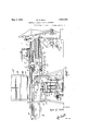
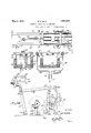
- FIG. 1 is a sideview of the apparatus, parts being broken away, in position as to a foodtray manufacturing machine;
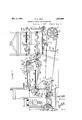
- Fig. 2 is a side View of the apparatus, from the opposite side shown in Fig. 1; I
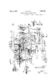
- Fig. 3 is a plan view of the operating mechanism for controlling the various steps of operation
- Fig. 3 is a fragmentary side View of tray interceptor
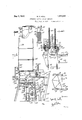
- Fig. 4 is a view on the line IV-IV, Fig. 2, looking in the direction of the arrow;
- Fig. 8 is a View in side elevation of Fig.
- Fig. 9 is a View on the line IXIX, Fig. 3;
- Fig. 10 is aview on the line X'X, Fig. 9;
- Fig. 11 is a side View of one of the clutch devices;
- I r n Fig. '12 is a view on the line XIIXII, Fig. 11;
- Fig. 13 is a View mi the'line XIIIfXIII
- Fig. 14 is a mechanism
- Fig. 14 is a detail view of the clutch operating mechanism operated by. the counting detail view of the counting mechanism from the'line XIV'XIV, Fig. 3
- Fig. 18 is a View on the line XVIII- XVIIL'Fig. 17;
- Fig. 19 is a View on Fig. 17;
- Fig. 20 is a view ontheline XXXX, Fig. 3.
- the tray In this swinging operatiomthe tray is thrust into entrance, between guides 26 to have edges 27 28,0f the tray,pass into seats 29 of sprocket chains 30, 31.
- crank arm- 32 from which extends link 33 having adjustable wrist pin connection 34 with arm 35 (Figs. 2, 5) loosely mounted on shaft 36-.
- This arm 35 extends past the shaft 36 as a lever and car- 'ri'es gravity.
- pawl 37 for; engagement with ratchet wheel 38 fixed with the shaft 36;
- This shaft 36 carries sprocket wheels 39, 40, about which extend the sprocket chains 31 to pass overrollers 41 as carried by frame extensions 42 adjacent the frame 1 of the machine to provide the lower drive for the nester.
- frame extensions 42 extend horizontally from side plates 43, 44, which-provide bearings 45 for the shaft 36.
- Sideplate 44 has bracket 46 carrying roller 47 about which extends sprocket chain 48 to be driven bysprocket wheel 49 (Figs. 2, 5) fixedly mounted on the shaft 36 adjacent the lever 35.
- This sprocket chain 48 as .actuatedby the sprocket wheel 49, passes about the roller 47 thence upward about sprocket wheel 50- on shaft51 mounted in bearings 52 carried from the side plates 43, 44.
- Sprocket wheels 53 are mounted on'this shaft 51 over the sprocket chains 31, for driving thepair of sprocket chains 30 (Fig. 5) with their seats 29 opposing the upwardly facing seats '291 of the lower pair of the sprocket chains 31.
- Frame extensions 55 (Fig. 2) abovethe frameextensions42, carry guide rollers 41 for the chains 30.
- Uounter control 7 Mounted. on thepl-ates 43,44, istmcka' 66 (:Fig. 1) carrying'the; frame extensions 55 mountingtherol lers 41 for the upper sprocket chains 30.
- the bracket 66 additionally carries box 67 housing insulation block 68 mounting shaft 69 on which is mounted toothed wheel 70 herein (Fig. 14) shown as provided with fourteen teeth.
- This Wheel 70 as mounted on the shaft 69 has fixed therewith cam 71 carrying pin 72 as a Geneva movement for effecting at each rotation of the shaft 69, one tooth movement of toothed wheel 73 on shaft 74 mounted in this box 67 for the block 68.
- Thi s wheel 73 has nine teeth.
- This wheel 73 carries lug 75 as anelectric terminal or contact projecting to engage spring terminal 76 also mountedby the .block 68. There is thus insulation mounting for this wheel 73 connected by terminal77 to the terminal or con tact 7 5. Accordingly, as the contact or terminal 7 5 engages the contact or terminal 76, circuitis closed between current delivery line 78 and current supply line 79 from battery 80, (Fig. 14'). The battery 80 has its terminal opposite from theline 79 connected to terminal 81. This line .78 extends to terminal 82 at coil device 83 which has theterminal 81. Thisdevice 83. is thereby energized from the battery 80 on the closing'of this circuit at the nester to draw in armature 84 and thus pull extension. arm 85 against the resistance of spring 86.
- This arm 85 is connected by link 87 to lever 88' (Fig. 3) having fixed mounting the switch 75, 76', is opened and the spring 86 throws the lever 88 into: position to cause the wedging apart or into unclutched relation of the members 90, 91-, against the resistance of the spring 92.
- the shaft 65 is mounted in bearings 93. i
- This shaft is provided with cam 94. igs. 3, 20) with which coacts roller 95 on lever 96 having fixed fulcrum 97 below the shaft 65.
- This lever 96' has adjustable wrist pin- 98 from which extends link 99 away from the machine frame lto adjustable wristpin connection 100 with lever 101 having lower fixed fulcrum 102.
- the roller 95 is held against the cam '91 by spring 1 03 connectedto the lever 101.
- This cam'94 has approximately 180 of short radius semi-circular portion with the operative cam throw enlargement portion effective in the rotation: of the shaft 65 to rock the lever 101 toward the machine frame 1.
- the lever 101- extends upwardly through slot 104 in trough bottom54.
- This trough-bottom 54 is provided with side plates 1 05.
- the lever 101 as extending upwardly through the slot- 104 in the tray trough bottom 54 and in the region above the side plates 105, 107, is provided with wrist pin 108 from which extends link 109 toward the machine frame 1, there to be connected with cross head 110 slidable on rods 111, 112, mounted by brackets 113, above the respective side plates 105, 107, 43, 44, and extending to the bracket 66.
- This cross head 110 is provided with horizontally extending channels 114 (Figs.
- This shaft 65 adjacent the cam 94 is provided with finger cam 117 (Figs. 3, 20) effective in rotation of the shaft 65 to act upon roller 118 mounted on lever 119 having fixed fulcrum 120, below the shaft 65.
- This lever 119 has adjustable extension 121 upwardly Tray interceptor from nester
- the plates 126 In the compacting action of this secondary compact-or,- the plates 126 as movable with the bracket 125 toward the region of the trough side plate 106, move into such region to effect the compacting before the primary compactor is effective and as the primary compactor is becoming effective by the moving of the plate 116, these plates 126 have a recover stroke back into the region between the plates 43, 44, and clear of the position of the side plate 106.
- finger cam 117 coactingiwith roller 118' on lever 119 having fixed fulcrum 120 mounted on bearing 202.
- This roller 118 is held against the cam 117 (Figs. 3, 3) by spring 121.
- This lever 119' carries upwardly extending bar 122' upwardly terminating in plate 123 which may be thrust through slot 124- in the trough bottom 54 at the region of the side plate 106 (Fig. 5).
- Thisfingercam 117" is of such extent that the plate 123' is thrustupward at once thehooks 127 have pulled the trays into the region of thesideplate 106.
- This plate 123 remains elevated to hold during the compacting and untilthe plate 156 is thrust transversely'of the tray bottom 54, and this plate 123' is then retracted by the spring 121 as permitted by the cam 117, so that there is clearance for the operation of the removable plate 106.
- the cam 117 is first effective causing operation of thehooks 127 to pull trays from the region of the trough having the side plates 43, 44, into the region of the trough side 106.
- the cam 94 is efiective to pushup away from the machine frame 1 the food trays in the tray trough Lateral clearance for tray transfer
- the shaft 65 is provided adj acentthe wheel 64 with bevel pinion 131 (Figs. 3, 9) in mesh with bevel'pinion 132 on shaft 133 mounted in bearings 134, 135.
- This shaft 133 has mounted thereon cam 136 with which coacts roller 137 (Fig. 4) carried by horizontally extending lever 138 having fixed bearing 139 carried by bracket 140.
- the roller 137 is held against the cam 136 by spring 141 engaging the lever 138 more adjacent the fulcrum 139 than theroller 137.
- This lever 138 is connected to vertically shiftable bar 142 mounted in guide 143 carried by fixed bracket 144.
- This bar 142 as upwardly extending beyond the lever 138, carries plate 145, as a trough side opposing the trough side 106.
- the spring 141 in this operation of the single cycle rotation of the shaft 133, the spring 141, as acting on the lever 138, pulls the roller 137 against the short radius portion of the cam 134 to depress or pull down the trough side plate 145 to leave clear. way along the trough opposite the trough side 106 and in the region where the trays have been compacted by the operation of the primary and secondary compactors.
- Spring 142' I supplements the spring 141 and acts directly on the bar 142 to take up lost motion.
- lever 151 mounted in fixed fulcrum bracket 152 therebelo-w.
- This lever 151 as upwardly extending, has an adjustable wrist pin connection 151short link 153 pivotally connected to slide 154 reciprocable in guide 155.
- This slide 154 carries plate 156 shiftable transversely-of the trough bottom 54, between the trough side 43 and trough side or plate 106 to position beyond the trough side 43 and beyond the drop position of the) trough side 145 between the position of the trough side 44 and the trough side 145.
- the shaft 133 between the bearings 134, 135, and adjacent the bearing 135 is provided with cam 157 coactingwith roller 158 9) on upwardly extending lever 159 mounted in fixed bearing 160 3) below the shaft 133.
- This lever 159 has adjustable extension 161 to which is connected horizontally extending spring 162' holding the lever 159, 161, so that the roller 158 is against the cam 157.
- This lever 159, 161 is provided with links 163, 164, extending to levers 165, 166, mounted in lower fixed fulcrum 167.
- These levers 165, 166, at their upper portions beyond the links 163, 164 have links 168 horizontally extending to brackets 169 engaging U-shaped trough.
- the platform 183 supports the lowermost carton 187 with its lower side in registry with the tray trough bottom 54 so that in the transfer of compacted trays by the shifting of the plate 106, such trays, as directed by the plate 156, are shifted over the dropped plate 145 into the carton 187.
- the cam 17 7 in its larger radius portion, extends to hold the platform 183 in such registry position with the tray trough bottom 54 while two transfers of trays have been made into the carton 187.
- the second transfer roup of trays merely pushes the firs; transfer back thus to form a two row charge in the instance that the carton is of such size to receive four rows of 125 trays eacn.
- Carton discharge drive Ratchet disk 176 carries cam face 189 (Figs. 9, 15) effective to rock arm 190 of angle lever having fixed fulcrum 191.
- This angle lever has drop arm 192 connected by link 193 to upstanding lever 194 having fixed lower fulcrum bracket 195;
- This cam face 189 as rocking the angle levers 190, 192, pulls lever 194 away from opposing clutch members 196, 197, to permit spring198 (Figs. 3, 11) on shaft 199 to throw the splined clutch face 196 into engagement with the driving clutchmember 197 fixed with gear wheel 200 loosely mounted on the shaft 199 andin mesh with the continuously running gear wheel 64.
- This shaft 199 is mounted in bearings 201,
- the shaft 199 Adjacent outboard of the bearing 201, the shaft 199 has fast thereon arm 203 having therefrom horizontally extending link 204 to upstanding lever 205 mounted in lower fixed fulcrum bearing 206.
- This lever 205 as upance channel 208 through the crosshead 183 parallel to the line of direction of the tray trough bottom 54 and disposed medially of the extent of the platform 183.
- This bar 207 on the-side of the carton chute, adjacent the machine frame 1, has upstanding pusher element 209 (Fig. 2). It is thus seen that at each fourth transfer operation for delivering trays from the tray trough into the carton, there is a coupling control from the intermittent grip device to effect couplingof the shaft 199 with the continuously operating drive pulley 64, for a single'rotation of the shaft 199 thereby to effect a full cycle of operation of the bar 207 and its element 209 in drawing such transversely of the platform 183 in moving the carton 187 from the vertical'carton chute 186 to conveyor or way 210 as a fully charged carton with the side 188 thereof still open.
- the overhangof the element 209 leaves the chute 186, an travels back into initial position.
- Carton feed control 8 Ward from the tray trough on the side of the carton chute, upwardly extending link 214 having pivotal connection to arm 215 on rock shaft 216 (Fig. 2) carried by bearings 217 of the carton chute 186.
- This rock shaft 216 has as a continuation of the arm 215, arm 218 from which extends upwardly'from'-'adjustable connection 219' link 219, to arm 220 on rock shaft 221 parallel to the rock shaft 216.
- This rock shaft 221 is mounted in bearings 222 carried by the carton chute frame 186. Fast on this rock shaft 221 are blocks 223 carrying depending spring fingers 224, normally held by torsion spring 225 about the shaft'221, to be thrown into the region of the carton chute 186 thereby engaging the succeeding carton.
- This engaging position is the one normally for these spring fingers 224.
- the lever 213 as controlled by the cam 211, against the resistance of spring 225, there may be a rocking of this shaft 221 to shift the fingers 224 clear ofsuch succeeding carton 187 so that its descent is timed to occur just as the element 209 has returned to its fully recovered position. There is accordingly a completion of this cycle of 'operations, for with a succeeding carton 187 in position, there isa repetition of the charging thereof.
- the high speed single rotation of the. shaft 199 is controlled against over travel by havtray sidewise into position along the intermittentlytraveling way provided by the opposing reaches of the sprocket chains 30, 31.
- this ratchet drive throughthe arm 35' from the tray formingmeans, the chains 30, 31,
- switch 75, 76 is closed to energize the coils 83 and thus" shift the-lever 88 to permit the clutch ,members 90, 91, to
- This driving provides a control, and actuates the hooks 125 to pull up the tray group from the supply end, isolating such definite quantity from'the supply so that stop gate plate 156 is a cut off against flow of trays from the machine during the carton charging operation.
- the compacting of the group of 125 trays is further effected by the travel of the depending plate 116, so that this group is located in the trough in the region of the side plate 106
- the plates 116,'126 serve as oppositely acting compactors
- the clutch connection for the cycle of operation as efioo fected bythe clutch members 90, 91 effects the rotation of the shaft 65 with the cams 118, 94, respectively effecting thecompacting operations of the hooks 125 and the plate 116.
- the cam117' positions the plate 156 as the cut-off gate for precluding further tray supply during the. carton charging.
- the shaft'133 driven. from the shaft 65 is effective through thecam 13.6 to lower lateral gate or trough side 145 oppositerthe trough side 106.
- the cam 157 on the shaft 133 is then effective to shift the trough side 106 crosswise of the trough and toward the side 145. in thereby rendering this transfer device effective in shifting the group of trays into the carton 187 laterally from the trough and through the chute.
- the lever 165 as shifting the trays into the carton, has connections effective for cara ton control actuationof the shaft 172 coacting through the controlling means of the cam 177 in providing positive charging means for determining the different positions of the container holder on the platform 183 for two group charges of trays at each level
- This carton controldrive is additionally effective through the cam 189 for control of the clutch members 196, 197. for operating'the pusher element-209 in withdrawing the fully charged carton from the stack.
- the gravity fall'of the succeeding empty carton for charging is controlled by the cam 211 from the shaft 172 as operating the fingers 224.
- the installation is thus, through the action of the machinery herein disclosed, in condition for continuing the carton charging operations with definite quantities of the articles as made and directly from the machine forming the articles, independently of the attention of an operator.
- An article handling machine comprising away for receiving articles in a'series, means for isolating sections of said series of articles as a group, said way having a lateral opening and a transfer device for removing saidfgroups from the Way through said opening.
- An article'h-andling machine comprising a trough for receiving articles in aseries
- a counter control for delivering articles to said' trough, means shiftable longitudinally of the trough for isolatinga section of said series of articles as a group,'and a transfer device for removing said group laterally from the trough as governed by the control.
- a vertical supply Way an article adjacent horizontal sup-ply way, means shiftable longitudinally of the supply way for isolat ing a group of articles, and transfer means controlled by the articles supplied for placing articles from the article supply way in the container supply vvay.
- machine for delivering articles, a drive therefrom, a trough from the machine to which-the machine delivers articles, and a grouping device for articles in the trough operable .by said drive, said device comprising oppositely shiftable article compacting means.
- a machine for grouping articles comprising a way in which the articles may be in a longitudinal series, pull-up means for articles in the way and a compactor oppositely movable as to the pull-up for acting upon articles in the Way.
- a machine for grouping articles comprising a way in which the articles may be 7 in a longitudinalseries, and oppositely acting compactors movable as to the Way for acting upon articles in the Way.
- a machine for grouping articles com: prising a Way in which the articles may be in a longitudinal series, charging means providing a supply for articles to said way, a compactor intermittently movable as to the Way for acting upon articles therebetween in the way, and means for isolating the supply from said compactor during compacting operationr 11.
- a .machine for grouping'articles comprising a Way in which the articles may be in a longitudinal series, charging means providing a supply for articles to said Way, a cut-off for the supply, and a compactor movable along the Way past the cut-off in advance of the cut-off operation.
- a machinefor grouping articles comprising a .Way in which thearticles may be in alongitudinal series, charging means providing a supply forarticles to said Way, a cut-off for the supply, a compactor movable along the way past the cut-off in advance of the cut-off operation, and a second opposing direction operation compactor effective for determiningv a group of articles.
- a machine for grouping'articles comprising a Way in whichthe articles may be in a longitudinal series, charging means providing a supply for articles to said Way, a
- a machine for grouping articles comprising a way in which the articles may be in a longitudinal series, charging means providing a supply for articles to said Way,.a cutofi for the supply, a compactor movable along the Way past the cut-off in advance of the cut-off operation, a second opposing direction operation compactor effective for determining a group of articles, alateral gate from the Way movable into open position as the compactors have operated, and a transfer device for moving the determined group of articles from the compactor and through said open gate.
- a machine for grouping articles com.- prising a Way inwhich the articles may be in a longitudinal series, charging means providing a supply for articles to said Way, a cut-ofi for the supply, a compactor movable along the way past the cut-01f in advance of the cut-0E operation, a second opposing direction operation compactor eifective for determining a group ofarti-cles, a lateral gate from the way movable into open position as the compactors have operated, a transfer device for moving the determined group of articles from the compactor and through said open gate, and a holder for a container to receive said determined group.
- a machine for grouping articles comprising a way, a transfer device movable transversely of the way for grouping articles from said way, and a ledge laterally of said way for receiving a plurality of said groupings of articles as delivered thereto transversely of the way of said transfer device.
- a machine for grouping articles comprising a way, a transfer device movable laterally across the way'for grouping articles for shifting transversely from said way, a vertical container holder laterally of the way for positioning a container at difi'erent levels to receive a plurality of said groupings of articles, and intermlttent drivlng means for controlling the dilferent positions for the container in the holder to receive different groupings of the articles.
- Container handling prising a vertical holder, horizontally operable container charging means movable-laterally of the holder for delivering articles into containers in said holder, and container positioning gravity means connected to be controlled by said charging means.
- Container handling mechanism comprising a first way having a discharge, container charging means embodying a supply wayand a pusher movable relatively transversely of said supply Way for shifting articles into containers in said first way, and container positioning means connected to be controlled by said charging means for rendering said container discharge effective.
- Container handling mechanism comprising a chute, a supply way, a transfer device for shifting articles from the chute to said way, position changing means for lowering a container as to the chute, including a transverse actuator for the charged containertherefrom, and connections between the transfer device and the container position changing means for effecting control therebetween.
Description
y 3, 1932- w. E.'HALL AUTOMATIC CARTON PACKING MACHINE Filed Sept. 6, 1927 6 Sheets-Sheet May 3, 1932. w HALL 1,857,082
AUTOMATIOCARTON PACKING MACHINE Filed Sept. *3. 192'? 6 Sheets-Sheet 2 May 3, 1932. w. E. HALL ,AUTOMATIC CARTON PACKING MACHINE Filed Sept. 6. 192'? 6 SheetsSheet K HR y 3, 1932- w. E. HALL 1,857,082
AUTOMATIC CARTON PACKING MACHINE iiled Sept. e, 1927 6 Sheets-Sheet 4 Q 006 N? r Y a; if
/ii ///i g 631/ 225 I W ma w m 2,, ma M 5 44 9" 6H0: new
y 3, 1932- w. E. HALL 1,857,082
AUTOMATIC CARTON PACKING MACHINE Filed Sept. s. 1927 s Shets-Sheet 5 May 3, 1932. w HALL 1,857,082
AUTOMATIC CARTON PACKING MACHINE Fi led Sept. 6. 192'? 6 Sheets-Sheet 6 2| 4" v 4 lo Patented May 3, 1932 I UNITE STATES PATENT oFFicE WILLIA E. HALL, or MONROE, MICHIGAN, ASSIGNOR 'ro FRED 'M.-L0NGNE0KER, or
. o 1 DELTA, OHIO- AUTO ATIC csn'ron PACKING, MACHINE Application filed September 6, 1927. Serial No. 217,601.
This apparatus relates to packaging machines. This apparatus has utility when incorporated in connection with food-tray manufacturing machines for packaging the completed food-trays in cartons, said food-trays being packed in measured quantities in the cartons, ready for carton sealing.
The articles, herein shown as food trays, 19 as coming from the machine forming or manufacturing such, are conducted into a stack or compressed group. The delivery to this group effects a counting of the articles. A carton to be charged is located alongside the way for the stack, and as a predetermined number of the articles are assembled in the stack, such group is transferred to the carton. With one level of the carton of capacity I to receive two groups, a second group thrusts the first group and thus completes a level of the stacks in the carton. The sequence of control is such that the carton is lowered to receive the third and fourth groups of trays v as over the first and second groups. Continuation of the machine operation efiects discharge of the completely filledcarton' with an empty carton in position for the repetition of the cycle of operations.
Referring to the drawings Fig. 1 is a sideview of the apparatus, parts being broken away, in position as to a foodtray manufacturing machine;
Fig. 2 is a side View of the apparatus, from the opposite side shown in Fig. 1; I
Fig. 3 is a plan view of the operating mechanism for controlling the various steps of operation; v
Fig. 3 is a fragmentary side View of tray interceptor Fig. 4 is a view on the line IV-IV, Fig. 2, looking in the direction of the arrow;
Fig. 5 is a partial plan view of the apparatus trough; I 1 a Fig. 6 is a partial side view of the conveyor mechanism for transporting the food-trays to the apparatus from the food-tray machifipe; V 1g. Fig. 5;
7 is a view on the line VIIVII,'
Fig. 8 is a View in side elevation of Fig.
'7' from the left; Y
Fig. 9 is a View on the line IXIX, Fig. 3; Fig. 10 is aview on the line X'X, Fig. 9; Fig. 11 is a side View of one of the clutch devices; I r n Fig. '12 is a view on the line XIIXII, Fig. 11;
Fig. 13 is a View mi the'line XIIIfXIII,
Fig. 9;
Fig. 14 is a mechanism;
Fig. 14 is a detail view of the clutch operating mechanism operated by. the counting detail view of the counting mechanism from the'line XIV'XIV, Fig. 3
' Fig. 18 is a View on the line XVIII- XVIIL'Fig. 17;
Fig. 19 is a View on Fig. 17; and
Fig. 20 is a view ontheline XXXX, Fig. 3.
Removing trays from the machine Frame 1 of machine for making food trays from sheet paper stock'is shown asmounted on base 2. Driving belt 3 extends to pulley 4 which may be thrown in by operating clutch lever 5 to drive shaft 6 having connection through gearing 7 for operating shaft 8. This shaft 8 is provided'with crank 9having adjustable wrist pin 10 from which extends link 11 to adjustable wrist pin 12 (Fig. 2) as fixed in crank. arm 13 on shaft 14: carried by brackets 15 from the frame'l. This crank arm 13 as fixed with the shaft 14 carries arm 16 from which upwardly extends link 17 having adjustable connection 18 with upwardly extending arm 19 fixed with shaft 20 carried-by the frame 1.
Fixed with this shaft 20,is a pair of arms 21 having hook termini 22 for catching under ends 23 of bottom up trays 24 as plunger 25 of the dish forming machinedescends. These hooks 22 of the arms 21 i'nthe rock operation the line XIXXIX,
of the shaft 20 as actuated from the rocking of the shaft 14 effect swinging of the trays 24 off from the plunger 25 while the plunger 25 is still descending.
In this swinging operatiomthe tray is thrust into entrance, between guides 26 to have edges 27 28,0f the tray,pass into seats 29 of sprocket chains 30, 31.
- 7 Tray nester Mounted on the shaft 20 is crank arm- 32 from which extends link 33 having adjustable wrist pin connection 34 with arm 35 (Figs. 2, 5) loosely mounted on shaft 36-. This arm 35. extends past the shaft 36 as a lever and car- 'ri'es gravity. pawl 37 for; engagement with ratchet wheel 38 fixed with the shaft 36; This shaft 36 carries sprocket wheels 39, 40, about which extend the sprocket chains 31 to pass overrollers 41 as carried by frame extensions 42 adjacent the frame 1 of the machine to provide the lower drive for the nester. These frame extensions 42 extend horizontally from side plates 43, 44, which-provide bearings 45 for the shaft 36.
' Sideplate 44 has bracket 46 carrying roller 47 about which extends sprocket chain 48 to be driven bysprocket wheel 49 (Figs. 2, 5) fixedly mounted on the shaft 36 adjacent the lever 35. This sprocket chain 48, as .actuatedby the sprocket wheel 49, passes about the roller 47 thence upward about sprocket wheel 50- on shaft51 mounted in bearings 52 carried from the side plates 43, 44.
Sprocket wheels 53 are mounted on'this shaft 51 over the sprocket chains 31, for driving thepair of sprocket chains 30 (Fig. 5) with their seats 29 opposing the upwardly facing seats '291 of the lower pair of the sprocket chains 31. Frame extensions 55 (Fig. 2) abovethe frameextensions42, carry guide rollers 41 for the chains 30. I
These chains as. to their opposing reaches travelfrom the frame 1 into the trough provide'd by the side plates 43, 44, to effect prog- "ress of the trays in nesting relation." This Fixedly mounted on;the shaft 8 adjacent the 3.111'129 (Fig. 2) is pulley 58 from which extends belt 59 to drive pulley 60 having shaft 61 mounted in bearings. 62. This shaft 61 is provided with'pinion 63 in mesh with gear 64 loosely mounted on shaft 65 (Fig. 3)}
Uounter control 7 Mounted. on thepl-ates 43,44, istmcka' 66 (:Fig. 1) carrying'the; frame extensions 55 mountingtherol lers 41 for the upper sprocket chains 30. The bracket 66 additionally carries box 67 housing insulation block 68 mounting shaft 69 on which is mounted toothed wheel 70 herein (Fig. 14) shown as provided with fourteen teeth. This Wheel 70 as mounted on the shaft 69 has fixed therewith cam 71 carrying pin 72 as a Geneva movement for effecting at each rotation of the shaft 69, one tooth movement of toothed wheel 73 on shaft 74 mounted in this box 67 for the block 68. Thi s wheel 73 has nine teeth. This wheel 73 carries lug 75 as anelectric terminal or contact projecting to engage spring terminal 76 also mountedby the .block 68. There is thus insulation mounting for this wheel 73 connected by terminal77 to the terminal or con tact 7 5. Accordingly, as the contact or terminal 7 5 engages the contact or terminal 76, circuitis closed between current delivery line 78 and current supply line 79 from battery 80, (Fig. 14'). The battery 80 has its terminal opposite from theline 79 connected to terminal 81. This line .78 extends to terminal 82 at coil device 83 which has theterminal 81. Thisdevice 83. is thereby energized from the battery 80 on the closing'of this circuit at the nester to draw in armature 84 and thus pull extension. arm 85 against the resistance of spring 86. This arm 85 is connected by link 87 to lever 88' (Fig. 3) having fixed mounting the switch 75, 76', is opened and the spring 86 throws the lever 88 into: position to cause the wedging apart or into unclutched relation of the members 90, 91-, against the resistance of the spring 92.
Primary compactor The shaft 65 is mounted in bearings 93. i
This shaft is provided with cam 94. igs. 3, 20) with which coacts roller 95 on lever 96 having fixed fulcrum 97 below the shaft 65.
This lever 96'has adjustable wrist pin- 98 from which extends link 99 away from the machine frame lto adjustable wristpin connection 100 with lever 101 having lower fixed fulcrum 102. The roller 95 is held against the cam '91 by spring 1 03 connectedto the lever 101. This cam'94 has approximately 180 of short radius semi-circular portion with the operative cam throw enlargement portion effective in the rotation: of the shaft 65 to rock the lever 101 toward the machine frame 1.
The lever 101- extends upwardly through slot 104 in trough bottom54. This trough-bottom 54 is provided with side plates 1 05. (Figs;
1, 17) in alignment with side plate 43- but spaced therefrom by plate 106. Opposing this side plate 105 and in alignment with the side plate 44 is side plate 107. The lever 101, as extending upwardly through the slot- 104 in the tray trough bottom 54 and in the region above the side plates 105, 107, is provided with wrist pin 108 from which extends link 109 toward the machine frame 1, there to be connected with cross head 110 slidable on rods 111, 112, mounted by brackets 113, above the respective side plates 105, 107, 43, 44, and extending to the bracket 66. This cross head 110 is provided with horizontally extending channels 114 (Figs. 17 19) as held in parallel relation by slidablecross bar 115 to provide a hold-down upper guide or shield for the trays as depending plate 116 (Figs. 1, 18) fixed with the cross head 110 is shifted by the Compactor, in the operation of the lever 101, toward the machine frame 1. This compactor, in the travel distance of the plate 116, shifts the trays from the region of the side plate 105 into the region of the side plate 106.
Secondary compactor This shaft 65 adjacent the cam 94 is provided with finger cam 117 (Figs. 3, 20) effective in rotation of the shaft 65 to act upon roller 118 mounted on lever 119 having fixed fulcrum 120, below the shaft 65. This lever 119 has adjustable extension 121 upwardly Tray interceptor from nester In the compacting action of this secondary compact-or,- the plates 126 as movable with the bracket 125 toward the region of the trough side plate 106, move into such region to effect the compacting before the primary compactor is effective and as the primary compactor is becoming effective by the moving of the plate 116, these plates 126 have a recover stroke back into the region between the plates 43, 44, and clear of the position of the side plate 106.
It is important in this recover stroke to initial position of the secondary compactor, that the primary compactor does not follow up to thrust the trays back into the initial region between the plates 43, 44. To this end there is provided a tray interceptor from the nester.
Mounted on the shaft 65 is finger cam 117 coactingiwith roller 118' on lever 119 having fixed fulcrum 120 mounted on bearing 202.
This roller 118 is held against the cam 117 (Figs. 3, 3) by spring 121. This lever 119' carries upwardly extending bar 122' upwardly terminating in plate 123 which may be thrust through slot 124- in the trough bottom 54 at the region of the side plate 106 (Fig. 5). Thisfingercam 117" is of such extent that the plate 123' is thrustupward at once thehooks 127 have pulled the trays into the region of thesideplate 106. This plate 123 remains elevated to hold during the compacting and untilthe plate 156 is thrust transversely'of the tray bottom 54, and this plate 123' is then retracted by the spring 121 as permitted by the cam 117, so that there is clearance for the operation of the removable plate 106. I
Compacting In the single rotation operation of the shaft 65, the cam 117 is first effective causing operation of thehooks 127 to pull trays from the region of the trough having the side plates 43, 44, into the region of the trough side 106. Quickly thereafter the cam 94 is efiective to pushup away from the machine frame 1 the food trays in the tray trough Lateral clearance for tray transfer The shaft 65 is provided adj acentthe wheel 64 with bevel pinion 131 (Figs. 3, 9) in mesh with bevel'pinion 132 on shaft 133 mounted in bearings 134, 135. This shaft 133 has mounted thereon cam 136 with which coacts roller 137 (Fig. 4) carried by horizontally extending lever 138 having fixed bearing 139 carried by bracket 140. The roller 137 is held against the cam 136 by spring 141 engaging the lever 138 more adjacent the fulcrum 139 than theroller 137. This lever 138 is connected to vertically shiftable bar 142 mounted in guide 143 carried by fixed bracket 144. This bar 142 as upwardly extending beyond the lever 138, carries plate 145, as a trough side opposing the trough side 106.
Accordingly, in this operation of the single cycle rotation of the shaft 133, the spring 141, as acting on the lever 138, pulls the roller 137 against the short radius portion of the cam 134 to depress or pull down the trough side plate 145 to leave clear. way along the trough opposite the trough side 106 and in the region where the trays have been compacted by the operation of the primary and secondary compactors. Spring 142' I supplements the spring 141 and acts directly on the bar 142 to take up lost motion.
with horizontally extending link 150 (Figs.
1, 3, 4), connected to upwardly extending lever 151 mounted in fixed fulcrum bracket 152 therebelo-w. This lever 151, as upwardly extending, has an adjustable wrist pin connection 151short link 153 pivotally connected to slide 154 reciprocable in guide 155. This slide 154 carries plate 156 shiftable transversely-of the trough bottom 54, between the trough side 43 and trough side or plate 106 to position beyond the trough side 43 and beyond the drop position of the) trough side 145 between the position of the trough side 44 and the trough side 145.
Tray transfer The shaft 133 between the bearings 134, 135, and adjacent the bearing 135 is provided with cam 157 coactingwith roller 158 9) on upwardly extending lever 159 mounted in fixed bearing 160 3) below the shaft 133. This lever 159 has adjustable extension 161 to which is connected horizontally extending spring 162' holding the lever 159, 161, so that the roller 158 is against the cam 157. This lever 159, 161, is provided with links 163, 164, extending to levers 165, 166, mounted in lower fixed fulcrum 167. These levers 165, 166, at their upper portions beyond the links 163, 164, have links 168 horizontally extending to brackets 169 engaging U-shaped trough. side 106 as a cross head for shifting such cross. head together with the trays as assembled in the trough adjacent thereto by the primary and secondary compactors. This shifting laterally of the tray occurs out of the line of travel of the trays along the tray trough bottom 54.
Drz'cc for carton supply control From the lever 165 horizontally extends link 170 to arm 171 (Figs. 9,15) loose on shaft 172 mounted above the shaft 133 in bearings 173, 174. This arm 171 is provided with" pawl 175 coacting with a' four toothed ratchet disk 17 6 fixed en the shaft 172. Ac-
cordingly, at each rocking of the lever 163 to efiect a transfer of trays from the trough 54, the ratchet 176 driven by the link 170 operates this shaft 172 for a quarter turn.
' Carton supply Fast on this shaft 172 is cam 177 with which coacts roller"178 on horizontally extending lever 179'having fixed bearing 180 (Fig. 4). This lever 179 as extending past the roller 178 from; the-bearing 180 has wrist pin 181 providing connection to depending bracket link 182, connected to the crosshead 183. Thiscrosshead 183 has fixed thereto depending brackets 185 reciprocable on guide rods 184 as fast with the base. These brackets 184 thus serve to direct up and down travel of platform 183 in rectangular vertical chute 186 into which cartons 187 may be stacked with open sides 188 toward thetray trough having bottom 54. V
The platform 183, as initially positioned, supports the lowermost carton 187 with its lower side in registry with the tray trough bottom 54 so that in the transfer of compacted trays by the shifting of the plate 106, such trays, as directed by the plate 156, are shifted over the dropped plate 145 into the carton 187. The cam 17 7, in its larger radius portion, extends to hold the platform 183 in such registry position with the tray trough bottom 54 while two transfers of trays have been made into the carton 187. The second transfer roup of trays merely pushes the firs; transfer back thus to form a two row charge in the instance that the carton is of such size to receive four rows of 125 trays eacn. a
The reduced speed drive of this shaft 172, as efiected by the intermittent grip device from the link 170, brings the cam 177 into its short radius portion for two feed operations as effected by the shifting of the trough side 106. This short radius portion of the cam 177 allows the lever 179 to lower the platform 183 a distance 'to permit the two successive compacted groups of trays to be shifted-into the carton 187 through its open side 188 above the two rows as supplied to the bottom side of the carton.
Carton discharge drive Ratchet disk 176 carries cam face 189 (Figs. 9, 15) effective to rock arm 190 of angle lever having fixed fulcrum 191. This angle lever has drop arm 192 connected by link 193 to upstanding lever 194 having fixed lower fulcrum bracket 195; This cam face 189 as rocking the angle levers 190, 192, pulls lever 194 away from opposing clutch members 196, 197, to permit spring198 (Figs. 3, 11) on shaft 199 to throw the splined clutch face 196 into engagement with the driving clutchmember 197 fixed with gear wheel 200 loosely mounted on the shaft 199 andin mesh with the continuously running gear wheel 64.
. This shaft 199 is mounted in bearings 201,
202. Adjacent outboard of the bearing 201, the shaft 199 has fast thereon arm 203 having therefrom horizontally extending link 204 to upstanding lever 205 mounted in lower fixed fulcrum bearing 206. This lever 205 as upance channel 208 through the crosshead 183 parallel to the line of direction of the tray trough bottom 54 and disposed medially of the extent of the platform 183.
This bar 207 on the-side of the carton chute, adjacent the machine frame 1, has upstanding pusher element 209 (Fig. 2). It is thus seen that at each fourth transfer operation for delivering trays from the tray trough into the carton, there is a coupling control from the intermittent grip device to effect couplingof the shaft 199 with the continuously operating drive pulley 64, for a single'rotation of the shaft 199 thereby to effect a full cycle of operation of the bar 207 and its element 209 in drawing such transversely of the platform 183 in moving the carton 187 from the vertical'carton chute 186 to conveyor or way 210 as a fully charged carton with the side 188 thereof still open. The overhangof the element 209 leaves the chute 186, an travels back into initial position.
Carton feed control 8 Ward from the tray trough on the side of the carton chute, upwardly extending link 214 having pivotal connection to arm 215 on rock shaft 216 (Fig. 2) carried by bearings 217 of the carton chute 186. This rock shaft 216 has as a continuation of the arm 215, arm 218 from which extends upwardly'from'-'adjustable connection 219' link 219, to arm 220 on rock shaft 221 parallel to the rock shaft 216. This rock shaft 221 is mounted in bearings 222 carried by the carton chute frame 186. Fast on this rock shaft 221 are blocks 223 carrying depending spring fingers 224, normally held by torsion spring 225 about the shaft'221, to be thrown into the region of the carton chute 186 thereby engaging the succeeding carton.
This engaging position is the one normally for these spring fingers 224. However, at the operation of the lever 213, as controlled by the cam 211, against the resistance of spring 225, there may be a rocking of this shaft 221 to shift the fingers 224 clear ofsuch succeeding carton 187 so that its descent is timed to occur just as the element 209 has returned to its fully recovered position. There is accordingly a completion of this cycle of 'operations, for with a succeeding carton 187 in position, there isa repetition of the charging thereof.
The high speed single rotation of the. shaft 199 is controlled against over travel by havtray sidewise into position along the intermittentlytraveling way provided by the opposing reaches of the sprocket chains 30, 31. By this ratchet drive throughthe arm 35' from the tray formingmeans, the chains 30, 31,
move in steps ahead to carry the on-edge trays in a longitudinal series past the counter wheel 70. At a predetermined counting,
' herein 125 for a four group five hundred tray holding carton, switch 75, 76, is closed to energize the coils 83 and thus" shift the-lever 88 to permit the clutch ,members 90, 91, to
effect a single cycle ofoperation driving from the carton forming machine as transmitted by the belt 59. i
This driving provides a control, and actuates the hooks 125 to pull up the tray group from the supply end, isolating such definite quantity from'the supply so that stop gate plate 156 is a cut off against flow of trays from the machine during the carton charging operation. The compacting of the group of 125 trays is further effected by the travel of the depending plate 116, so that this group is located in the trough in the region of the side plate 106 The plates 116,'126,serve as oppositely acting compactors, The clutch connection for the cycle of operation as efioo fected bythe clutch members 90, 91, effects the rotation of the shaft 65 with the cams 118, 94, respectively effecting thecompacting operations of the hooks 125 and the plate 116. p The cam117' .positions the plate 156 as the cut-off gate for precluding further tray supply during the. carton charging.
The shaft'133 driven. from the shaft 65 is effective through thecam 13.6 to lower lateral gate or trough side 145 oppositerthe trough side 106. The cam 157 on the shaft 133 is then effective to shift the trough side 106 crosswise of the trough and toward the side 145. in thereby rendering this transfer device effective in shifting the group of trays into the carton 187 laterally from the trough and through the chute.
The lever 165, as shifting the trays into the carton, has connections effective for cara ton control actuationof the shaft 172 coacting through the controlling means of the cam 177 in providing positive charging means for determining the different positions of the container holder on the platform 183 for two group charges of trays at each level This carton controldrive is additionally effective through the cam 189 for control of the clutch members 196, 197. for operating'the pusher element-209 in withdrawing the fully charged carton from the stack. The gravity fall'of the succeeding empty carton for charging is controlled by the cam 211 from the shaft 172 as operating the fingers 224. The installation is thus, through the action of the machinery herein disclosed, in condition for continuing the carton charging operations with definite quantities of the articles as made and directly from the machine forming the articles, independently of the attention of an operator.
What is claimed and it is desired to secure by Letters Patent is:
2. An article'h-andling machine comprising a trough for receiving articles in aseries,
a counter control for delivering articles to said' trough, means shiftable longitudinally of the trough for isolatinga section of said series of articles as a group,'and a transfer device for removing said group laterally from the trough as governed by the control. 7
3. A vertical supply Way, an article adjacent horizontal sup-ply way, means shiftable longitudinally of the supply way for isolat ing a group of articles, and transfer means controlled by the articles supplied for placing articles from the article supply way in the container supply vvay. I
4. A container supply Way,-an'articlesupply Way, transfer means controlled by the articles'supplied for placing articles from the article supply Way in the container supply way, a drive for the means, and an article counter controlled by the drive embodying means shiftable longitudinally of the supply Way for isolating a group of articles.
5. A packaging .machinecomprising-an article supply trough, .areceiving chute laterallyadjacentthereto, supply cut-off means for grouping articles in the trough in the region of the chute, and .a transfer device movable relatively to the cut-off means for laterally shifting the grouped articles from c the trough into the chute.
6. machine for delivering articles, a drive therefrom, a trough from the machine to which-the machine delivers articles, and a grouping device for articles in the trough operable .by said drive, said device comprising oppositely shiftable article compacting means. g 7. A machine I for delivering articles, a drive therefrom, a trough from the machine to Which the machine delivers articles, a groupingdevicefor articles in the trough operable in the trough, by said drive longitudinally of the trough, and a counter for controlling saiddev-ice operation.
8. A machine for grouping articles comprising a way in which the articles may be in a longitudinal series, pull-up means for articles in the way and a compactor oppositely movable as to the pull-up for acting upon articles in the Way.
9. A machine for grouping articles comprising a way in which the articles may be 7 in a longitudinalseries, and oppositely acting compactors movable as to the Way for acting upon articles in the Way. I
10. A machine for grouping articles com: prising a Way in which the articles may be in a longitudinal series, charging means providing a supply for articles to said way, a compactor intermittently movable as to the Way for acting upon articles therebetween in the way, and means for isolating the supply from said compactor during compacting operationr 11. A .machine for grouping'articles comprising a Way in which the articles may be in a longitudinal series, charging means providing a supply for articles to said Way, a cut-off for the supply, and a compactor movable along the Way past the cut-off in advance of the cut-off operation.
12. A machinefor grouping articles comprising a .Way in which thearticles may be in alongitudinal series, charging means providing a supply forarticles to said Way, a cut-off for the supply, a compactor movable along the way past the cut-off in advance of the cut-off operation, and a second opposing direction operation compactor effective for determiningv a group of articles.
13. A machine for grouping'articles comprising a Way in whichthe articles may be in a longitudinal series, charging means providing a supply for articles to said Way, a
cut-oif for the supply, a compactor movable along the way past the cut-off in advance of the cut-off operation, a second opposing direction operation compactor effective for determini-mg a group of articles, and a transfer device for moving the determined group of articles from the compactor.
14. A machine for grouping articles comprising a way in which the articles may be in a longitudinal series, charging means providing a supply for articles to said Way,.a cutofi for the supply, a compactor movable along the Way past the cut-off in advance of the cut-off operation, a second opposing direction operation compactor effective for determining a group of articles, alateral gate from the Way movable into open position as the compactors have operated, and a transfer device for moving the determined group of articles from the compactor and through said open gate.
15. A machine for grouping articles com.- prising a Way inwhich the articles may be in a longitudinal series, charging means providing a supply for articles to said Way, a cut-ofi for the supply, a compactor movable along the way past the cut-01f in advance of the cut-0E operation, a second opposing direction operation compactor eifective for determining a group ofarti-cles, a lateral gate from the way movable into open position as the compactors have operated, a transfer device for moving the determined group of articles from the compactor and through said open gate, and a holder for a container to receive said determined group.
16. A machine for grouping articles comprising a way, a transfer device movable transversely of the way for grouping articles from said way, and a ledge laterally of said way for receiving a plurality of said groupings of articles as delivered thereto transversely of the way of said transfer device.
17 A machine for grouping articles comprising a way, a transfer device movable laterally across the way'for grouping articles for shifting transversely from said way, a vertical container holder laterally of the way for positioning a container at difi'erent levels to receive a plurality of said groupings of articles, and intermlttent drivlng means for controlling the dilferent positions for the container in the holder to receive different groupings of the articles.
18. Container handling prising a vertical holder, horizontally operable container charging means movable-laterally of the holder for delivering articles into containers in said holder, and container positioning gravity means connected to be controlled by said charging means.
19. Container handling mechanism comprising a first way having a discharge, container charging means embodying a supply wayand a pusher movable relatively transversely of said supply Way for shifting articles into containers in said first way, and container positioning means connected to be controlled by said charging means for rendering said container discharge effective.
20. Container handling mechanism comprising a chute, a supply way, a transfer device for shifting articles from the chute to said way, position changing means for lowering a container as to the chute, including a transverse actuator for the charged containertherefrom, and connections between the transfer device and the container position changing means for effecting control therebetween. In witness whereof I at'liX my signature.
WILLIAM E. HALL.
mechanism com-
Priority Applications (1)
| Application Number | Priority Date | Filing Date | Title |
|---|---|---|---|
| US217601A US1857082A (en) | 1927-09-06 | 1927-09-06 | Automatic carton packing machine |
Applications Claiming Priority (1)
| Application Number | Priority Date | Filing Date | Title |
|---|---|---|---|
| US217601A US1857082A (en) | 1927-09-06 | 1927-09-06 | Automatic carton packing machine |
Publications (1)
| Publication Number | Publication Date |
|---|---|
| US1857082A true US1857082A (en) | 1932-05-03 |
Family
ID=22811740
Family Applications (1)
| Application Number | Title | Priority Date | Filing Date |
|---|---|---|---|
| US217601A Expired - Lifetime US1857082A (en) | 1927-09-06 | 1927-09-06 | Automatic carton packing machine |
Country Status (1)
| Country | Link |
|---|---|
| US (1) | US1857082A (en) |
Cited By (4)
| Publication number | Priority date | Publication date | Assignee | Title |
|---|---|---|---|---|
| US2675152A (en) * | 1951-01-06 | 1954-04-13 | Abbott Machine Co | Bobbin packing mechanism |
| US2737327A (en) * | 1951-04-27 | 1956-03-06 | Wilson | Machine for filling cases or boxes with packages |
| US4292785A (en) * | 1978-09-20 | 1981-10-06 | Anchor Building Products Limited | Tile packaging |
| US5329748A (en) * | 1993-01-19 | 1994-07-19 | Sencorp Systems, Inc. | Nested plastic tray separator apparatus packaging system and method |
-
1927
- 1927-09-06 US US217601A patent/US1857082A/en not_active Expired - Lifetime
Cited By (4)
| Publication number | Priority date | Publication date | Assignee | Title |
|---|---|---|---|---|
| US2675152A (en) * | 1951-01-06 | 1954-04-13 | Abbott Machine Co | Bobbin packing mechanism |
| US2737327A (en) * | 1951-04-27 | 1956-03-06 | Wilson | Machine for filling cases or boxes with packages |
| US4292785A (en) * | 1978-09-20 | 1981-10-06 | Anchor Building Products Limited | Tile packaging |
| US5329748A (en) * | 1993-01-19 | 1994-07-19 | Sencorp Systems, Inc. | Nested plastic tray separator apparatus packaging system and method |
Similar Documents
| Publication | Publication Date | Title |
|---|---|---|
| US2681171A (en) | Box loading and conveying machine | |
| US1896639A (en) | Automatic box loader | |
| US1904613A (en) | Article collecting machine | |
| US3024890A (en) | Article handling apparatus | |
| US1993619A (en) | Apparatus for removing the bottom cigarette group from a cigarette distributing chamber | |
| US1964084A (en) | Automatic cigarette stacker | |
| US1839925A (en) | Article packing machine | |
| US1857082A (en) | Automatic carton packing machine | |
| US1954842A (en) | Box packing machine | |
| US2966020A (en) | Packing machine | |
| US1515589A (en) | Packaging machine | |
| US1985547A (en) | Delivery mechanism | |
| US817375A (en) | Packing-machine. | |
| US2634874A (en) | Shipping case unloading apparatus | |
| US1412227A (en) | Packaging machine | |
| US1920762A (en) | Method of treating articles produced in one machine and consumed in another machine | |
| US3004374A (en) | Apparatus for collecting cigarettes in receptacles | |
| US1985765A (en) | Cigar feeding mechanism | |
| US1869653A (en) | Can feeding apparatus | |
| US814454A (en) | Packing-machine. | |
| US3225847A (en) | Weighing machine | |
| US3410052A (en) | Machine for handling articles and containers | |
| US1437409A (en) | Article feeding and collating mechanism | |
| US1592426A (en) | Machine for packing biscuits | |
| US3041803A (en) | Cartoning machine |