US1856973A - Quick change chuck - Google Patents
Quick change chuck Download PDFInfo
- Publication number
- US1856973A US1856973A US426258A US42625830A US1856973A US 1856973 A US1856973 A US 1856973A US 426258 A US426258 A US 426258A US 42625830 A US42625830 A US 42625830A US 1856973 A US1856973 A US 1856973A
- Authority
- US
- United States
- Prior art keywords
- collet
- lugs
- tool
- chuck
- lug
- Prior art date
- Legal status (The legal status is an assumption and is not a legal conclusion. Google has not performed a legal analysis and makes no representation as to the accuracy of the status listed.)
- Expired - Lifetime
Links
Images
Classifications
-
- B—PERFORMING OPERATIONS; TRANSPORTING
- B23—MACHINE TOOLS; METAL-WORKING NOT OTHERWISE PROVIDED FOR
- B23B—TURNING; BORING
- B23B31/00—Chucks; Expansion mandrels; Adaptations thereof for remote control
- B23B31/02—Chucks
- B23B31/10—Chucks characterised by the retaining or gripping devices or their immediate operating means
- B23B31/107—Retention by laterally-acting detents, e.g. pins, screws, wedges; Retention by loose elements, e.g. balls
- B23B31/1072—Retention by axially or circumferentially oriented cylindrical elements
-
- B—PERFORMING OPERATIONS; TRANSPORTING
- B23—MACHINE TOOLS; METAL-WORKING NOT OTHERWISE PROVIDED FOR
- B23B—TURNING; BORING
- B23B31/00—Chucks; Expansion mandrels; Adaptations thereof for remote control
- B23B31/02—Chucks
- B23B31/10—Chucks characterised by the retaining or gripping devices or their immediate operating means
- B23B31/107—Retention by laterally-acting detents, e.g. pins, screws, wedges; Retention by loose elements, e.g. balls
- B23B31/1078—Retention by wedges
-
- B—PERFORMING OPERATIONS; TRANSPORTING
- B23—MACHINE TOOLS; METAL-WORKING NOT OTHERWISE PROVIDED FOR
- B23B—TURNING; BORING
- B23B2260/00—Details of constructional elements
- B23B2260/02—Cams
-
- Y—GENERAL TAGGING OF NEW TECHNOLOGICAL DEVELOPMENTS; GENERAL TAGGING OF CROSS-SECTIONAL TECHNOLOGIES SPANNING OVER SEVERAL SECTIONS OF THE IPC; TECHNICAL SUBJECTS COVERED BY FORMER USPC CROSS-REFERENCE ART COLLECTIONS [XRACs] AND DIGESTS
- Y10—TECHNICAL SUBJECTS COVERED BY FORMER USPC
- Y10S—TECHNICAL SUBJECTS COVERED BY FORMER USPC CROSS-REFERENCE ART COLLECTIONS [XRACs] AND DIGESTS
- Y10S279/00—Chucks or sockets
- Y10S279/904—Quick change socket
-
- Y—GENERAL TAGGING OF NEW TECHNOLOGICAL DEVELOPMENTS; GENERAL TAGGING OF CROSS-SECTIONAL TECHNOLOGIES SPANNING OVER SEVERAL SECTIONS OF THE IPC; TECHNICAL SUBJECTS COVERED BY FORMER USPC CROSS-REFERENCE ART COLLECTIONS [XRACs] AND DIGESTS
- Y10—TECHNICAL SUBJECTS COVERED BY FORMER USPC
- Y10T—TECHNICAL SUBJECTS COVERED BY FORMER US CLASSIFICATION
- Y10T279/00—Chucks or sockets
- Y10T279/17—Socket type
- Y10T279/17666—Radially reciprocating jaws
- Y10T279/17692—Moving-cam actuator
- Y10T279/17743—Reciprocating cam sleeve
Definitions
- This invention relates to quick change chucks, and has to do particularly with an extremely simple and compact tool holder embodying tool securing and releasing Quick change chucks, or what might be termed tool holders having easily removable collets, are in quite general use and the most successful of such type tool holders have embodied some means which may be actuated while the tool holder is still in motion to release the collet and working tool and which means may also be actuated while the tool holder is still in motion to permit the collet in a new tool to be inserted into position.
- this general type of quick change chuck required two separate operations in the changing of tools, but so far as I am aware, such chucks have embodied a complicated and expensive design.
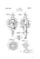
- Fig. 1 is a longitudinal sectional view of a combined tool holder and collet embodying my invention. f v
- Fig. 2 is a view similarto Fig. 1 but illus trating the manner of actuating a part of the chuck whereby to release the collet.
- Fig. 3 is a sectional view taken 33 of Fig. 1.
- Fig. 4 is a sectional view taken on line 4-4 of Fig. 1.
- Fig. 5 is an enlarged perspective view of one of the novel lug members for controlling the locking and releasing of the collet.
- a quick change chuck of the type embodied on line in the presnt invention usually contains three standard elements; namely, the tool, the collet for holding the same, and the tool holder.
- the tool itself may be generally designated 1 and the collet for receiving the same 2.
- This collet is preferably cylindrical in shape and at the lower end thereof is provided with a collar 3 and diametrically positioned lug members 4.
- the upper end of the collet 2 is preferably milled away as at 5 and 6 to provide suitable slots for cooperrating in the locking and releasing of the collet as will be later pointed out.
- the tool holder may be generally designated 7 and in detail this tool holder consists of the usual tapered shank 8 and a cylindrical downwardly extending hollow portion 9 for receiving the collet.
- the interior wall of the downwardly extending portion 9 is preferably ground so as to have a close sliding fit with the ground surface of the upper cylindrical end of the collet 2.
- This downwardly extending annular portion 9 is also provided with diametrically formed slots 10 which are adapted to receive and position lug members 11.
- These lug members are fabricated to closely fit and slide within the slots 10 and are each provided with a suitable tapered surface 12 on the inner lower side thereof, a substantially V-shaped groove 13, as best shown in Fig. 5, and a suitable transverse groove 14 on the outer surface thereof.
- Adapted'to cooperate with the grooves 13 is an outer annular member 15.
- This member 15 is rotatably mounted on the outer surface of the member 9 and preferably the outer surface of the member 9 and the inner surface of the member'15 are ground so as to provide for easy relative rotation between the two members.
- the member 15 is adapted to be held in 7 position by a collar 16.
- Such collar 16 and the member 15 are fabricated for threaded engagement as at 17 and the tool holder 7 is preferably provided with a suitable flange 18 for rotatably receiving an inwardly extending flange 19 of the collar 16. It will thus be seenthat the entire casing or shell formed by the member 15 and the collar 16 isrotatably positioned relative to the tool holder 7 so that if such casing or shell is grasped by the hand it will remain stationary while the main portion of the tool holder continuously rotates in either direction.
- the upper end of the member 15 is prefertil ably tapered as at 20 and this tapered portion 20 is adapted to remain in constant engagement with a portion of the V-shaped slot 13 in each of the lugs 11.
- Such lugs 11 are subjected to a constant spring pressure by means of a partially coiled spring 21 which encircles the lower end 9 of the tool holder and is held in position by a pin 21a and. engages the lugs at the grooves 14-. It will thus be seen that the lug members 11 are normally forced inwardly.-
- the tapered portion 12 of the lug members 11 is so designed thatthe lower edge of the taper 12, when thelugs are in innermost-post, tion, as shown in Fi g. 1, will just register with the inner surface of the member 9. In other words, when the member 15 is in lowermost position, regardless of whether the collect is in position or not, the lug members will be in the position shown in Fig. 1.
- the lower end of the annular extension 9 s provined with diametrically positioned slots 22 and these slots 22 are adapted to receive the lug members 4 of the collect so that the actual driving takes place between the tool holder and the collet at this point.
- WVhat I claim is 11 A toolof the characterdescribed, comprising a chuck having an annular collet receiving member and diametrically positioned slots for receiving engaging and releasing lugs, means normally tending to move said lugs inwardly, a flange on said annular mcm ber, and a rotatable sleeve member formed in two parts, one part engaging said flange to hold said sleeve in position on the chuck and the other part having means for engaging said lugs to move the same outwardly when said sleeve is moved in an axial direction, said lugs being freely movable independently of said sleeve when said sleeve is in normal position whereby to be automatically actuated when said collet is moved into position.
- a tool chuck comprising a hollow colletreceiving member having slot-s therein, radially slidable lugs in the slots, a collet for disposition within the member notched to receive the lugs, means urging the lugs radially inwardly to lock the collet in said member, a collar outside said member axially movable thereon, a cam surface on each lug, and cam means on the collar coacting with the cam surfaces on the lugs to retract them from engagement with the collar upon axial movementot the collar.
- a tool chuck comprising a hollow collet-- receiving member having slots therein, radially slidable'lugs in the slots, a'rcollet for disposition within the member notched to receive the lugs, means urging the lugs radially inwardly to lock thecollet in said member, a colar outside said member axially movable thereon, a cam surface on each lug, and cam means on the colar' co'a'cting with the camsu'rfa'c'e's onv the lugs to retract them from en'gagement'w'ith' the collar upon axial movement of the collar, said means for'holding'the lugs radially inwardly comprising a spring.
- a receiving member having slots" therein, radially slid'able lugs in th'eslots, a collet for disposition within thehollow m'e'mber notched to receive the lugs, a cam surface on each lug, collar rotatably mounted on said. member and axially movable with thereto, a trusto conically sliaped men'iber ca'rrie'd by-thecollar, the conical surface of which coacts with the cam surfaces on the lugs whereby to'retrac t' them from engagenient withthe collet upon axial movement of the collar V Y 5.
- a tool chuck comprisinga hollow col let-receiving member having slots therein.
- each lug a collar rotatatiy' mounted on said member and axially movable with respect thereto, a frustoeconically shaped member carried by the collar,the conical surface of which co'acts with the cam surfaces on the lugs whereby to retract them from engagetool chuc'kcbfnprising a hollow collet ment with the collet upon axial movement of the collar, said lugs being radially movable outwardly independently of the collar and said lugs having other cam faces for engagement with the collet whereby insertion of the collet within said member cams the lugs outwardly.
- a tool chuck comprising a. hollow colletreceiving member, a notched collet therein, said hollow member having slots therein, a radially slidable lug in each slot, spring means for urging the lugs inwardly to engage the notched portion of the collet, a cam surface on the inner edge of each lug for camming the lugs outwardly upon entrance of the collet, another cam surface on each lug, a sleeve outside said member having cam means for coacting with the second named cam surfaces on the lugs, said sleeve being axially movable whereby the coacting surfaces on the lug and sleeve move the lugs radially outwardly for collet release.
- a tool chuck comprising a hollow colletreceiving member provided With slots, a lug in each slot, a notched collet, spring means for urging the lugs into the notched collet, cam surfaces on the inside edge of each lug for automatic lug actuation upon insertion of the collet, a V shaped notch in each lug, an axially movable sleeve outside said member and rotatable thereonhavinga frusto-conical part engaged in the V shaped notches, said frustoconical surface contacting with one side of the V shaped notches upon axial movement of the sleeve to move the lugs radially outward for collet release.
- a collet a receiving chuck having radially movable lug members for positioning or releasing the said collet, said lug members having a cam surface, and a freely rotatable sleeve having a cam surface, mounted on said chuck and movable axially of the tool, an axial movement of the sleeve causing the cam surface of the sleeve to press against the cam surface of the lugs resulting in a radially outward movement of the lugs releasing the collet.
- a collet a receiving chuck having radially movable lug members for p0- sitioning or releasing the collet, said lug members having a cam surface, means for pressing the lugs radially inward engaging the collet, a freely rotatable sleeve having a cam surface, mounted on said chuck and movable axially of the tool, an axial movement of the sleeve causing the cam surface of the sleeve to lugs resulting in a radially outward movement of the lugs releasing the collet, and interengaging means on said chuck and said collet for effecting driving of the collet.
- lug members for positioning or releasing the said collet, said lug members having a notch, means for pressing the lugs radially inward engaging the collet, and a freely rotatable sleeve having a cam surface, mounted on said chuck and movable axially of the tool, an axial movement of the sleeve causing the cam surface of the sleeve to press against one surface of the notch in each lug resulting in a radially outward movement of the lugs releasing the collet, and interengaging means of said chuck and said collet for efiecting driving of the collet in either direction independently of said positioning and releasing lugs.
Description
May 3, 1932. J, H, SMI H 1,856,973
QUICK CHANGE CHUCK Filed Feb. 6, 1930 INVENTOR J0 nfiugofimzih law/i g/z/ ATTORNEY means.
Patented May 3, 1932 PATENT OFFICE JOHN HUGO SMITH, OF DETROIT, MICHIGAN QUICK CHANGE CHUCK Application filed February 6, 1930. Serial No. 426,258.
This invention relates to quick change chucks, and has to do particularly with an extremely simple and compact tool holder embodying tool securing and releasing Quick change chucks, or what might be termed tool holders having easily removable collets, are in quite general use and the most successful of such type tool holders have embodied some means which may be actuated while the tool holder is still in motion to release the collet and working tool and which means may also be actuated while the tool holder is still in motion to permit the collet in a new tool to be inserted into position. Thus, not only has this general type of quick change chuck required two separate operations in the changing of tools, but so far as I am aware, such chucks have embodied a complicated and expensive design.
It is the object of the present invention to provide a quick change chuck which embodies a minimum number of parts, is very easy and inexpensive to manufacture, which requires only one operation in the removal and inserting of the tool, and which is adapted to release or receive a tool regardless of the direction of rotation of the tool holder.
In the drawings: V
Fig. 1 is a longitudinal sectional view of a combined tool holder and collet embodying my invention. f v
Fig. 2 is a view similarto Fig. 1 but illus trating the manner of actuating a part of the chuck whereby to release the collet.
Fig. 3 is a sectional view taken 33 of Fig. 1.
Fig. 4 is a sectional view taken on line 4-4 of Fig. 1.
Fig. 5 is an enlarged perspective view of one of the novel lug members for controlling the locking and releasing of the collet.
A quick change chuck of the type embodied on line in the presnt invention usually contains three standard elements; namely, the tool, the collet for holding the same, and the tool holder. In the embodiment illustrated in the drawings, the tool itself may be generally designated 1 and the collet for receiving the same 2. This collet is preferably cylindrical in shape and at the lower end thereof is provided with a collar 3 and diametrically positioned lug members 4. The upper end of the collet 2 is preferably milled away as at 5 and 6 to provide suitable slots for cooperrating in the locking and releasing of the collet as will be later pointed out.
The tool holder may be generally designated 7 and in detail this tool holder consists of the usual tapered shank 8 and a cylindrical downwardly extending hollow portion 9 for receiving the collet. The interior wall of the downwardly extending portion 9 is preferably ground so as to have a close sliding fit with the ground surface of the upper cylindrical end of the collet 2.
This downwardly extending annular portion 9 is also provided with diametrically formed slots 10 which are adapted to receive and position lug members 11. These lug members are fabricated to closely fit and slide within the slots 10 and are each provided with a suitable tapered surface 12 on the inner lower side thereof, a substantially V-shaped groove 13, as best shown in Fig. 5, and a suitable transverse groove 14 on the outer surface thereof. Adapted'to cooperate with the grooves 13 is an outer annular member 15. This member 15 is rotatably mounted on the outer surface of the member 9 and preferably the outer surface of the member 9 and the inner surface of the member'15 are ground so as to provide for easy relative rotation between the two members.
The member 15 is adapted to be held in 7 position by a collar 16. Such collar 16 and the member 15 are fabricated for threaded engagement as at 17 and the tool holder 7 is preferably provided with a suitable flange 18 for rotatably receiving an inwardly extending flange 19 of the collar 16. It will thus be seenthat the entire casing or shell formed by the member 15 and the collar 16 isrotatably positioned relative to the tool holder 7 so that if such casing or shell is grasped by the hand it will remain stationary while the main portion of the tool holder continuously rotates in either direction.
The upper end of the member 15 is prefertil ably tapered as at 20 and this tapered portion 20 is adapted to remain in constant engagement with a portion of the V-shaped slot 13 in each of the lugs 11. Such lugs 11 are subjected to a constant spring pressure by means of a partially coiled spring 21 which encircles the lower end 9 of the tool holder and is held in position by a pin 21a and. engages the lugs at the grooves 14-. It will thus be seen that the lug members 11 are normally forced inwardly.-
Thus upward movement of the shell member, consisting of the parts 15 and 16', will result in the tapered portions 20 fully entering the V-shaped grooves 13 of the lug 11 causing outward radial movementzot said lugs and inasmuch as the lug members 11 are the sole means for holding the collet and its tool in position, it will'be obvious that suhicient upward movement of the member 15' will result in complete release of the collet.
The tapered portion 12 of the lug members 11 is so designed thatthe lower edge of the taper 12, when thelugs are in innermost-post, tion, as shown in Fi g. 1, will just register with the inner surface of the member 9. In other words, when the member 15 is in lowermost position, regardless of whether the collect is in position or not, the lug members will be in the position shown in Fig. 1. The lower end of the annular extension 9 s provined with diametrically positioned slots 22 and these slots 22 are adapted to receive the lug members 4 of the collect so that the actual driving takes place between the tool holder and the collet at this point.
In operation of my quick change chuck, and assuming a tool and its collet is in position as shown in Fig. 1, and that the machine is operating, it will be obvious that'in order to release the collet it is only necessary for the operator to grab the rotatable shell member and then move the same upwardly. This rotatable shell member when grasped will, of course, remain stationary without affecting any other parts, but the moment it is moved upwardly to suflicient extent, the lug members 11 will be forced outwardly, as shown in Fig. 2, and the collet immediately released. The operator will grasp the released collet and its tool with his other hand. In inserting another tool and its collet into position, it is only necessary for the operator to insert the collet into the rotating chuck, as shown in Fig. 2, and move the same up wardly until the lug members 4 register with the slots 22 when the collet may be forced home with one hand. The upper end of the cylindrical member 2 will contact with the tapered surface 12 of the lug members and force the same outwardly until said lug members again return to their locking position, as shown in Fig. 1.
WVhat I claim is 11 A toolof the characterdescribed, comprising a chuck having an annular collet receiving member and diametrically positioned slots for receiving engaging and releasing lugs, means normally tending to move said lugs inwardly, a flange on said annular mcm ber, and a rotatable sleeve member formed in two parts, one part engaging said flange to hold said sleeve in position on the chuck and the other part having means for engaging said lugs to move the same outwardly when said sleeve is moved in an axial direction, said lugs being freely movable independently of said sleeve when said sleeve is in normal position whereby to be automatically actuated when said collet is moved into position.
2. A tool chuck comprising a hollow colletreceiving member having slot-s therein, radially slidable lugs in the slots, a collet for disposition within the member notched to receive the lugs, means urging the lugs radially inwardly to lock the collet in said member, a collar outside said member axially movable thereon, a cam surface on each lug, and cam means on the collar coacting with the cam surfaces on the lugs to retract them from engagement with the collar upon axial movementot the collar.
3. A tool chuck comprising a hollow collet-- receiving member having slots therein, radially slidable'lugs in the slots, a'rcollet for disposition within the member notched to receive the lugs, means urging the lugs radially inwardly to lock thecollet in said member, a colar outside said member axially movable thereon, a cam surface on each lug, and cam means on the colar' co'a'cting with the camsu'rfa'c'e's onv the lugs to retract them from en'gagement'w'ith' the collar upon axial movement of the collar, said means for'holding'the lugs radially inwardly comprising a spring.
4. A receiving member having slots" therein, radially slid'able lugs in th'eslots, a collet for disposition within thehollow m'e'mber notched to receive the lugs, a cam surface on each lug, collar rotatably mounted on said. member and axially movable with thereto, a trusto conically sliaped men'iber ca'rrie'd by-thecollar, the conical surface of which coacts with the cam surfaces on the lugs whereby to'retrac t' them from engagenient withthe collet upon axial movement of the collar V Y 5. A tool chuck comprisinga hollow col let-receiving member having slots therein. radially slidable lugs iii the slots, a collet for disposition within the liollo'x'v member notched to receive the lugs, a cam surface on; each lug, a collar rotatatiy' mounted on said member and axially movable with respect thereto, a frustoeconically shaped member carried by the collar,the conical surface of which co'acts with the cam surfaces on the lugs whereby to retract them from engagetool chuc'kcbfnprising a hollow collet ment with the collet upon axial movement of the collar, said lugs being radially movable outwardly independently of the collar and said lugs having other cam faces for engagement with the collet whereby insertion of the collet within said member cams the lugs outwardly.
6. A tool chuck comprising a. hollow colletreceiving member, a notched collet therein, said hollow member having slots therein, a radially slidable lug in each slot, spring means for urging the lugs inwardly to engage the notched portion of the collet, a cam surface on the inner edge of each lug for camming the lugs outwardly upon entrance of the collet, another cam surface on each lug, a sleeve outside said member having cam means for coacting with the second named cam surfaces on the lugs, said sleeve being axially movable whereby the coacting surfaces on the lug and sleeve move the lugs radially outwardly for collet release.
7. A tool chuck comprising a hollow colletreceiving member provided With slots, a lug in each slot, a notched collet, spring means for urging the lugs into the notched collet, cam surfaces on the inside edge of each lug for automatic lug actuation upon insertion of the collet, a V shaped notch in each lug, an axially movable sleeve outside said member and rotatable thereonhavinga frusto-conical part engaged in the V shaped notches, said frustoconical surface contacting with one side of the V shaped notches upon axial movement of the sleeve to move the lugs radially outward for collet release.
8. In a. tool of the character described, the combination of a collet, a receiving chuck having radially movable lug members for positioning or releasing the said collet, said lug members having a cam surface, and a freely rotatable sleeve having a cam surface, mounted on said chuck and movable axially of the tool, an axial movement of the sleeve causing the cam surface of the sleeve to press against the cam surface of the lugs resulting in a radially outward movement of the lugs releasing the collet.
9. In a tool of the character described, the combination of a collet, a receiving chuck having radially movable lug members for p0- sitioning or releasing the collet, said lug members having a cam surface, means for pressing the lugs radially inward engaging the collet, a freely rotatable sleeve having a cam surface, mounted on said chuck and movable axially of the tool, an axial movement of the sleeve causing the cam surface of the sleeve to lugs resulting in a radially outward movement of the lugs releasing the collet, and interengaging means on said chuck and said collet for effecting driving of the collet.
10. In a tool of the character described, the combination of a collet, a receiving chuck press against the cam surface of the.
having radially movable lug members for positioning or releasing the said collet, said lug members having a notch, means for pressing the lugs radially inward engaging the collet, and a freely rotatable sleeve having a cam surface, mounted on said chuck and movable axially of the tool, an axial movement of the sleeve causing the cam surface of the sleeve to press against one surface of the notch in each lug resulting in a radially outward movement of the lugs releasing the collet, and interengaging means of said chuck and said collet for efiecting driving of the collet in either direction independently of said positioning and releasing lugs.
In testimony whereof I affix my signature.
JOHN HUGO SMITH.
Priority Applications (1)
| Application Number | Priority Date | Filing Date | Title |
|---|---|---|---|
| US426258A US1856973A (en) | 1930-02-06 | 1930-02-06 | Quick change chuck |
Applications Claiming Priority (1)
| Application Number | Priority Date | Filing Date | Title |
|---|---|---|---|
| US426258A US1856973A (en) | 1930-02-06 | 1930-02-06 | Quick change chuck |
Publications (1)
| Publication Number | Publication Date |
|---|---|
| US1856973A true US1856973A (en) | 1932-05-03 |
Family
ID=23690021
Family Applications (1)
| Application Number | Title | Priority Date | Filing Date |
|---|---|---|---|
| US426258A Expired - Lifetime US1856973A (en) | 1930-02-06 | 1930-02-06 | Quick change chuck |
Country Status (1)
| Country | Link |
|---|---|
| US (1) | US1856973A (en) |
Cited By (6)
| Publication number | Priority date | Publication date | Assignee | Title |
|---|---|---|---|---|
| US3612552A (en) * | 1968-08-21 | 1971-10-12 | Bruendler Paul | Quick change tool holder |
| US4594036A (en) * | 1983-05-20 | 1986-06-10 | Kenneth R. Muzzy | Quick change tool chuck system |
| US4655631A (en) * | 1985-02-08 | 1987-04-07 | Rogers Tool Works, Inc. | Quick change tool holder |
| US4784543A (en) * | 1987-08-25 | 1988-11-15 | Rogers Tool Works, Inc. | Quick change tool holder |
| US4836706A (en) * | 1985-02-08 | 1989-06-06 | Rogers Tool Works, Inc. | Quick change tool holder |
| US5961257A (en) * | 1997-03-03 | 1999-10-05 | Cembre S.P.A. | Drill for drilling crossties, particularly for use in the railroad sector |
-
1930
- 1930-02-06 US US426258A patent/US1856973A/en not_active Expired - Lifetime
Cited By (6)
| Publication number | Priority date | Publication date | Assignee | Title |
|---|---|---|---|---|
| US3612552A (en) * | 1968-08-21 | 1971-10-12 | Bruendler Paul | Quick change tool holder |
| US4594036A (en) * | 1983-05-20 | 1986-06-10 | Kenneth R. Muzzy | Quick change tool chuck system |
| US4655631A (en) * | 1985-02-08 | 1987-04-07 | Rogers Tool Works, Inc. | Quick change tool holder |
| US4836706A (en) * | 1985-02-08 | 1989-06-06 | Rogers Tool Works, Inc. | Quick change tool holder |
| US4784543A (en) * | 1987-08-25 | 1988-11-15 | Rogers Tool Works, Inc. | Quick change tool holder |
| US5961257A (en) * | 1997-03-03 | 1999-10-05 | Cembre S.P.A. | Drill for drilling crossties, particularly for use in the railroad sector |
Similar Documents
| Publication | Publication Date | Title |
|---|---|---|
| US3398965A (en) | Quick change tool holder | |
| US2526998A (en) | Self-centering detachable coupling for machine tools | |
| US4032163A (en) | Quick change in-motion tool chuck | |
| US3947047A (en) | Quick-change collet | |
| US3708178A (en) | Progressive-tightening spindle chuck for milling machines or other machine tools | |
| JPS62114887A (en) | Tool holder | |
| US4381116A (en) | Futter chuck | |
| JP6550264B2 (en) | Fastening chuck with fast exchange function and tightening mechanism | |
| JPH0230806B2 (en) | ||
| US2511416A (en) | Toolholder | |
| US1856973A (en) | Quick change chuck | |
| US3405950A (en) | Tool holder | |
| US3219355A (en) | Tool holder | |
| US5820135A (en) | Counter centrifugal chuck and mounting systems | |
| US1513332A (en) | Chuck | |
| US1907553A (en) | Automatic chuck | |
| US3116068A (en) | Torque transmitting connecting mechanism | |
| US4284285A (en) | Self-adjusting rotary chuck | |
| US1686601A (en) | Chuck | |
| US1129491A (en) | Chuck. | |
| US2462465A (en) | Chuck for lathes and the like machine tools | |
| US1764291A (en) | Drill chuck | |
| US2985457A (en) | Tool holder | |
| US1935645A (en) | Stop chuck | |
| US2502216A (en) | Collet chuck |