US185697A - Improvement in nozzles for cans - Google Patents
Improvement in nozzles for cans Download PDFInfo
- Publication number
- US185697A US185697A US185697DA US185697A US 185697 A US185697 A US 185697A US 185697D A US185697D A US 185697DA US 185697 A US185697 A US 185697A
- Authority
- US
- United States
- Prior art keywords
- valve
- cans
- nozzles
- seat
- nozzle
- Prior art date
- Legal status (The legal status is an assumption and is not a legal conclusion. Google has not performed a legal analysis and makes no representation as to the accuracy of the status listed.)
- Expired - Lifetime
Links
- 210000001331 Nose Anatomy 0.000 description 10
- 239000012530 fluid Substances 0.000 description 8
- 210000003128 Head Anatomy 0.000 description 2
- 210000000088 Lip Anatomy 0.000 description 2
- 210000002832 Shoulder Anatomy 0.000 description 2
- 238000010276 construction Methods 0.000 description 2
- 230000000694 effects Effects 0.000 description 2
- 239000007788 liquid Substances 0.000 description 2
- 238000004519 manufacturing process Methods 0.000 description 2
- 239000002184 metal Substances 0.000 description 2
- 210000004894 snout Anatomy 0.000 description 2
- 238000005476 soldering Methods 0.000 description 2
Images
Classifications
-
- B—PERFORMING OPERATIONS; TRANSPORTING
- B65—CONVEYING; PACKING; STORING; HANDLING THIN OR FILAMENTARY MATERIAL
- B65D—CONTAINERS FOR STORAGE OR TRANSPORT OF ARTICLES OR MATERIALS, e.g. BAGS, BARRELS, BOTTLES, BOXES, CANS, CARTONS, CRATES, DRUMS, JARS, TANKS, HOPPERS, FORWARDING CONTAINERS; ACCESSORIES, CLOSURES, OR FITTINGS THEREFOR; PACKAGING ELEMENTS; PACKAGES
- B65D47/00—Closures with filling and discharging, or with discharging, devices
- B65D47/04—Closures with discharging devices other than pumps
- B65D47/20—Closures with discharging devices other than pumps comprising hand-operated members for controlling discharge
- B65D47/24—Closures with discharging devices other than pumps comprising hand-operated members for controlling discharge with poppet valves or lift valves, i.e. valves opening or closing a passageway by a relative motion substantially perpendicular to the plane of the seat
- B65D47/241—Closures with discharging devices other than pumps comprising hand-operated members for controlling discharge with poppet valves or lift valves, i.e. valves opening or closing a passageway by a relative motion substantially perpendicular to the plane of the seat the valve being opened or closed by actuating a cap-like element
- B65D47/242—Closures with discharging devices other than pumps comprising hand-operated members for controlling discharge with poppet valves or lift valves, i.e. valves opening or closing a passageway by a relative motion substantially perpendicular to the plane of the seat the valve being opened or closed by actuating a cap-like element moving helically
Definitions
- cans are used for containing fluids it generally becomes desirable to provide some device for closing the nose or snout of the can, except when it is in use.
- the means most usually employed for this purpose are a stopper entering within and filling the end of the nose, or a thimble or cap sliding on over the end.
- the principal element in the invention being a valve capable of being moved to and from its seat by the action of a hollow screw, upon which it is mounted, and which constitutes a part of this nozzle.
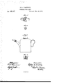
- Figure 1 is a lon gitudinal section of the improved nozzle.
- Fig. 2 is an end view of the part which carries the valve, and
- Fig. 3 is a view of the nozzle as applied to the nose of an ordinary can.
- the nozzle is made in three parts, a, b, and c.
- the part a is constructed so as to be capable of attachment, in any suitable way, directly to the nose of the can, and is provided at one end with the valve-seat d.
- This valveseat preferably takes the form of the frustum of a hollow cone, the aperture through it being sufficiently large to permit of the ready flow of the fluid past the valve-stem whenever the valve is raised from its seat.
- the part b moves longitudinally upon the part a, and supports and carries the valve 0, the attachment of the valve thereto being the most readily efi'ected by means of the cross-bar in the end of the part b.
- valve is made conical in form
- the part c is attached to the part b, and is designed simply as a guide for conveying away the fluid after it has passed through the nozzle proper.
- this nozzle By rotating the part b upon its axis in the proper direction the valve is raised from its seat and held in position to permit the flow of the fluid past it, through the orifice in the valve-seat, and through the openings 9 g in the head of the part b. By reversing the axial motion of the part b the valve will be forced into contact with its seat, and the discharge-orifice will be closed.
- these two parts should be provided with shoulders 41 t, constructed so as to jam tightly against each other when the valve is fully opened for the discharge of the contents of the can.
- This improved nozzle will ordinarily be made of sheet metal. It can be made of any desirable size, and sold as a separate article of manufacture, and can be readily applied to the nose of an ordinary can, either by soldering or by any other well-known mode of attachment.
- any suitable packing, h may be attached to it, whereby to effect closer contact between it and the valve-seat. In this case it may be well to turn the edge of the valve-seat into a lip, that will bite sharply into the packing, as shown.
- valve-nozzle consisting of the two parts, moving longitudinally upon each other, and provided with a valve adapted to operate substantially as described.
- the screw-nozzle consisting of the two screws 0, and b, and provided with a valve, to be operated by the movement of the one screw upon the other, substantially as and for the purpose described.
Description
s. R. PINCKNEY.
- NOZZLES FOR CANS.
No.185,697. Patented Dec. 26, 1876.
THE GRAPHIC 0O. N-Y
UNITED STATES.
PATENT OFFICE.
I STEPHEN B. PINOKNEY, OF NEW YORK, N. Y.
IMPROVEMENT IN NOZZLES FOR CANS.
Specification forming part of Letters Patent No. I 85,697, dated December 26, 1876; application filed November 1, 1876.
To all whom it may concern:
Be it known that I, STEPHEN R. PINOK- NEY, of the city of New York, in the State of New York, have invented a new and useful Improvement in Nozzles for Cans, of which the following is a specification:
Where cans are used for containing fluids it generally becomes desirable to provide some device for closing the nose or snout of the can, except when it is in use. The means most usually employed for this purpose are a stopper entering within and filling the end of the nose, or a thimble or cap sliding on over the end. By the present invention it is sought to provide an improved mechanism for this purpose, the principal element in the invention being a valve capable of being moved to and from its seat by the action of a hollow screw, upon which it is mounted, and which constitutes a part of this nozzle.
The invention is illustrated in the accompanying drawing, in which Figure 1 is a lon gitudinal section of the improved nozzle. Fig. 2 is an end view of the part which carries the valve, and Fig. 3 is a view of the nozzle as applied to the nose of an ordinary can.
The nozzle is made in three parts, a, b, and c. The part a is constructed so as to be capable of attachment, in any suitable way, directly to the nose of the can, and is provided at one end with the valve-seat d. This valveseat preferably takes the form of the frustum of a hollow cone, the aperture through it being sufficiently large to permit of the ready flow of the fluid past the valve-stem whenever the valve is raised from its seat. The part b moves longitudinally upon the part a, and supports and carries the valve 0, the attachment of the valve thereto being the most readily efi'ected by means of the cross-bar in the end of the part b. The longitudinal movement of the part b upon the part a, whereby the valve is forced home to its seat, or is raised therefrom, is effected by means of the screw form given to the walls of the two parts, the diameters of these parts being such that the one fits closely within the other.
Preferably the valve is made conical in form,
as shown. The part c is attached to the part b, and is designed simply as a guide for conveying away the fluid after it has passed through the nozzle proper.
The operation of this nozzle is clear. By rotating the part b upon its axis in the proper direction the valve is raised from its seat and held in position to permit the flow of the fluid past it, through the orifice in the valve-seat, and through the openings 9 g in the head of the part b. By reversing the axial motion of the part b the valve will be forced into contact with its seat, and the discharge-orifice will be closed.
In order to prevent a back-flow of the liquid, carrying it in between the two screws, a and b, these two parts should be provided with shoulders 41 t, constructed so as to jam tightly against each other when the valve is fully opened for the discharge of the contents of the can.
This improved nozzle will ordinarily be made of sheet metal. It can be made of any desirable size, and sold as a separate article of manufacture, and can be readily applied to the nose of an ordinary can, either by soldering or by any other well-known mode of attachment.
Instead of making the parts a and b in the form of screws, they can be left as plain cylinders, sliding the one within the other. It is believed, however, that the screw form of construction will be found the most effective for the purpose intended.
By making the valve as shown in Fig. 4, any suitable packing, h, may be attached to it, whereby to effect closer contact between it and the valve-seat. In this case it may be well to turn the edge of the valve-seat into a lip, that will bite sharply into the packing, as shown.
What is claimed as new is l. The valve-nozzle, consisting of the two parts, moving longitudinally upon each other, and provided with a valve adapted to operate substantially as described.
2. The screw-nozzle, consisting of the two screws 0, and b, and provided with a valve, to be operated by the movement of the one screw upon the other, substantially as and for the purpose described.
STEPHEN R. PINUKNEY.
Witnesses:
SAML. A. DUNCAN, BENJ. A. SMITH.
Publications (1)
| Publication Number | Publication Date |
|---|---|
| US185697A true US185697A (en) | 1876-12-26 |
Family
ID=2255103
Family Applications (1)
| Application Number | Title | Priority Date | Filing Date |
|---|---|---|---|
| US185697D Expired - Lifetime US185697A (en) | Improvement in nozzles for cans |
Country Status (1)
| Country | Link |
|---|---|
| US (1) | US185697A (en) |
-
0
- US US185697D patent/US185697A/en not_active Expired - Lifetime
Similar Documents
| Publication | Publication Date | Title |
|---|---|---|
| US2874881A (en) | Liquid dispensing device | |
| US525744A (en) | Oil-can | |
| US795676A (en) | Dispensing apparatus. | |
| US3207388A (en) | Fluid handling devices | |
| US185697A (en) | Improvement in nozzles for cans | |
| EP1102969A1 (en) | Dosing and measuring device for flowing media | |
| US1905301A (en) | Bottle stopper and the like | |
| US228132A (en) | Oil-can spout | |
| US947991A (en) | Spout for oil-cans. | |
| US733701A (en) | Combined nozzle and tap. | |
| US2044912A (en) | Fountain syringe | |
| US185180A (en) | Improvement in lubricating - bottles | |
| US174840A (en) | Improvement in oil-cans | |
| US477455A (en) | Can for liquids | |
| US921085A (en) | Oil-can. | |
| US2150485A (en) | Dispenser | |
| US3180539A (en) | Fluid dispensing arrangement | |
| US261357A (en) | Oil-can | |
| US595112A (en) | Alexius posgay | |
| US1097187A (en) | Bottle-stopper. | |
| US1005668A (en) | Collapsible tube. | |
| US628258A (en) | Faucet. | |
| US359305A (en) | Screw-cap for collapsible tubes | |
| US281189A (en) | Oil-can | |
| US174131A (en) | Improvement in oil-can nozzles |