US185683A - Improvement in harvester-frame adjusters - Google Patents
Improvement in harvester-frame adjusters Download PDFInfo
- Publication number
- US185683A US185683A US185683DA US185683A US 185683 A US185683 A US 185683A US 185683D A US185683D A US 185683DA US 185683 A US185683 A US 185683A
- Authority
- US
- United States
- Prior art keywords
- harvester
- journal
- frame
- wheel
- improvement
- Prior art date
- Legal status (The legal status is an assumption and is not a legal conclusion. Google has not performed a legal analysis and makes no representation as to the accuracy of the status listed.)
- Expired - Lifetime
Links
- XEEYBQQBJWHFJM-UHFFFAOYSA-N iron Chemical compound [Fe] XEEYBQQBJWHFJM-UHFFFAOYSA-N 0.000 description 4
- 230000000994 depressed Effects 0.000 description 2
- 230000003028 elevating Effects 0.000 description 2
- 229910052742 iron Inorganic materials 0.000 description 2
- 239000002965 rope Substances 0.000 description 2
Images
Classifications
-
- A—HUMAN NECESSITIES
- A01—AGRICULTURE; FORESTRY; ANIMAL HUSBANDRY; HUNTING; TRAPPING; FISHING
- A01D—HARVESTING; MOWING
- A01D67/00—Undercarriages or frames specially adapted for harvesters or mowers; Mechanisms for adjusting the frame; Platforms
Definitions
- the present invention consists in a stirrup placed over the periphery of the drive-wheel, and provided with holes in the ends, through which ajournal is put, the wheel having holes through it to admit of the passage of the journal.
- the journal of the drive-wheel is adjustable by means of pins in its boxes, whereby it can be held at the adjusted height.
- Figure l is a plan view of the drive-wheel of a harvester and its supporting-frame, showing also the elevating devices.
- Fig. 2 is a section of the drive-wheel, taken longitudinally with its axis, showing also the boxes of the wheel, the stirrup, chains, journal, and frame-pieces.
- G represents the drive-wheel of a harvester, and m is its journal.
- a B 0 D is the harvester-frame, supporting the wheel, and N is the tongue.
- E E I I represent the boxes fastened to theframe, and supporting the journal m of the wheel.
- the parts or wings I I of the boxes are formed such distance apart as to receive the ends of the journal at and form a guide for it when the frame is elevated or depressed, and the parts E are attached rigidly to the frame-pieces AD.
- the journal is held in position, when adjusted, by means of pins F F put through holes in the wings I I, as shown in Fig. 2.
- iron stirrup, J with holes in its ends, is placed over the periphery of the wheel G, and through the said holes in the stirrup and through a hole in the wheel is placed a journal, S, to whose ends are affixed chains or ropes L, which are attached to the boxes E.
Description
L. F. KING &. H. M. FUNK.
HARVESTER FRAME ADJUSTER.
No.185,683. Patented Dec. 26,1876.
G if J B I JV Z1 UNITED STATES PATENT OFFICE.
LURANUS F. KING AND HENRY M. FUNK, OF POLO, ILLINOIS.
IMPROVEMENT IN HARVESTER-FRAME ADJUSTERS.
Specification forming part of Letters Patent No. 185,683, dated December 26, 1876; application filed May 8, 1876.
To all whom at may concern:
Be it known that we, LURANUS F. KING and HENRY M. FUNK, of P010, in the county of Ogle and State of Illinois, have invented a new and useful Improvement in Adjustments for Harvester-Frames, of which the following is a specification:
The present invention consists in a stirrup placed over the periphery of the drive-wheel, and provided with holes in the ends, through which ajournal is put, the wheel having holes through it to admit of the passage of the journal. To the journal, outside of the stirrup, are fastened chains, which connect with the boxes of the drive-wheel, so that when the journal is rotated by a suitable wrench the frame of the harvester will be elevated, and bring the cutter-bar farther above the surface of the ground. The journal of the drive-wheel is adjustable by means of pins in its boxes, whereby it can be held at the adjusted height.
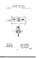
In the drawings, Figure l is a plan view of the drive-wheel of a harvester and its supporting-frame, showing also the elevating devices. Fig. 2 is a section of the drive-wheel, taken longitudinally with its axis, showing also the boxes of the wheel, the stirrup, chains, journal, and frame-pieces.
G represents the drive-wheel of a harvester, and m is its journal. A B 0 D is the harvester-frame, supporting the wheel, and N is the tongue. E E I I represent the boxes fastened to theframe, and supporting the journal m of the wheel. The parts or wings I I of the boxes are formed such distance apart as to receive the ends of the journal at and form a guide for it when the frame is elevated or depressed, and the parts E are attached rigidly to the frame-pieces AD. The journal is held in position, when adjusted, by means of pins F F put through holes in the wings I I, as shown in Fig. 2.
The foregoing is a description of those parts of a harvester which are operated on by our improvement, which is as follows: An'
iron stirrup, J, with holes in its ends, is placed over the periphery of the wheel G, and through the said holes in the stirrup and through a hole in the wheel is placed a journal, S, to whose ends are affixed chains or ropes L, which are attached to the boxes E.
The operation is as follows: In Fig. 2 the shaft 122 has a central adjustment. Now, to lower the frame A D on the wheel, apply a wrench to the journal S, so as to relieve the upper pins F; then remove said pin and place it in the hole above, turning the journal S to wind the chains L, to bring the journal m up to the position of the replaced pin F. The lower pins F are then removed and placed in the second holes from the top of the boxes E I. To raise the frame, first remove the pins F below the journal m, and put them in the lower holes; then draw the chains till the upper pins F can be placed where the lower pins now are. The stirrup, chains, and journa-l S are removed, or one chain is left aflixed to the box for safe-keepiii g.
We claim as new and desire to secure by Letters Patent The combination of the stirrup J, chain L,
journal S, guide-boxes E I, shaft m, frame A D, drive-wheel G, and pins F, as and for the purpose set forth.
LURANUS F. KING. HENRY M. FUNK. Witnesses:
J. D. CAMPBELL, H. H. SMITH.
Publications (1)
| Publication Number | Publication Date |
|---|---|
| US185683A true US185683A (en) | 1876-12-26 |
Family
ID=2255089
Family Applications (1)
| Application Number | Title | Priority Date | Filing Date |
|---|---|---|---|
| US185683D Expired - Lifetime US185683A (en) | Improvement in harvester-frame adjusters |
Country Status (1)
| Country | Link |
|---|---|
| US (1) | US185683A (en) |
-
0
- US US185683D patent/US185683A/en not_active Expired - Lifetime
Similar Documents
| Publication | Publication Date | Title |
|---|---|---|
| US185683A (en) | Improvement in harvester-frame adjusters | |
| US114549A (en) | Improvement in horse-powers | |
| US45550A (en) | Improvement in harvesters | |
| US118584A (en) | Improvement in corn-markers | |
| US153755A (en) | Improvement in lawn-mowers | |
| US342227A (en) | Potato-digger | |
| US79300A (en) | babcock | |
| US34090A (en) | Improvement in harvesters | |
| US256484A (en) | jones | |
| US113750A (en) | Improvement in horse-powers | |
| US56405A (en) | Improvement in harrows | |
| US276320A (en) | worth | |
| US16612A (en) | Attaching the arms of horse-powers | |
| US346665A (en) | Windmill | |
| US26612A (en) | Improvement in seed-drills | |
| US134327A (en) | Improvement in dumping-trucks | |
| US130242A (en) | Improvement in stump-extractors | |
| US224427A (en) | Lewis w | |
| US134251A (en) | Improvement in corn-harvesters | |
| US256751A (en) | Harvester | |
| US163275A (en) | Improvement in harvesters | |
| US315624A (en) | Frame-adjusting mechanism for harvesters | |
| US195438A (en) | Improvement in stump-extractors | |
| US72411A (en) | Aethue a | |
| US115097A (en) | Improvement in barrel-cars |