US185676A - Improvement in machines for jointing staves - Google Patents
Improvement in machines for jointing staves Download PDFInfo
- Publication number
- US185676A US185676A US185676DA US185676A US 185676 A US185676 A US 185676A US 185676D A US185676D A US 185676DA US 185676 A US185676 A US 185676A
- Authority
- US
- United States
- Prior art keywords
- staves
- stave
- piece
- slotted
- frame
- Prior art date
- Legal status (The legal status is an assumption and is not a legal conclusion. Google has not performed a legal analysis and makes no representation as to the accuracy of the status listed.)
- Expired - Lifetime
Links
- 230000036633 rest Effects 0.000 description 10
- 210000000474 Heel Anatomy 0.000 description 2
- 230000000875 corresponding Effects 0.000 description 2
Images
Classifications
-
- B—PERFORMING OPERATIONS; TRANSPORTING
- B27—WORKING OR PRESERVING WOOD OR SIMILAR MATERIAL; NAILING OR STAPLING MACHINES IN GENERAL
- B27H—BENDING WOOD OR SIMILAR MATERIAL; COOPERAGE; MAKING WHEELS FROM WOOD OR SIMILAR MATERIAL
- B27H3/00—Manufacture of constructional elements of tubes, coops, or barrels
- B27H3/02—Manufacture of barrel staves
Definitions
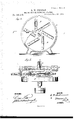
- Figure l is a side elevation, in section, on line .70 m in Fig. 2.
- Fig. 2 is a front elevation.
- Fig. 3 is a detail view of a part of the stavecentering apparatus.
- Fig. 4 is a side view of one of the rotary cutters and its casing.
- Fig. 5 is a top view, in part section, on line 3 y in Fig. 4.
- My invention consists in arranging two rotary concave cutterdisks, facing each other, upon a single shaft, each disk being provided with knives arranged tangential to a circle of small diameter described from the center of the disk.
- a casing surrounds each disk, which is connected with an exhaust-fan for removing the shavings. It also consists in adjustable guide plates or rests, attached to the side of the casing for supporting the stave. It further consists in a pivoted frame for carrying the stave centering and clamping apparatus.
- the object of the invention is to joint the edges of staves expeditiously and accurately, and to proportion the width of the ends of the staves to the width of the center.
- a A are the easings for the concave disks, which also form a support for the journal-boxes B of the shaft E.
- F F are disks keyed to the shaft E, which face each other, and are concaved to correspond with the convexity of the edge of a stave of average width, and are provided with cutters or knives G, which are secured to the beveled edges of slots D, cut through the disks F F, tangential to a circle of small diameter described from the center of the disk.
- the knives when arranged in this manner, are less liable to heat and wear near the heel than those arranged in the ordinary way.
- the casings A A are provided with doors G, for convenience in removing and adjusting the knives, and also with the adjustable rests a, which project through an opening, b, in the casings A A, and are provided with convex edges, that conform to the concavity of the cutter-disks. These rests are slotted vertically, and screws (1 pass through the slots into the casings.
- the legs of the casings A A are hollow, and form passages for the escape of the shavings to a conveyor, or to a pipe connected with an exhaust-fan.
- H is a frame, that is pivoted in L-shaped pieces attached to the floor midway between the casings.
- a curved bar, I is attached to the floor at the end of the frame H, and a lockle'ver, e, pivoted to the end of the said frame, looks into a hole made in the center of the curved bar, when it is desired to hold the frame in a vertical position.
- the frame H is of such height as to reach above the shaft E, and receives a bar, J, which is pivoted to the said frame at f.
- An angle-plate, g is attached to the end of the bar J, the horizontally-projecting portion of which is slotted to receive an eccentric, It, which is pivoted in a handle, '5, that projects horizontally from the upper side of the frame H.
- a bed-piece, K upon which the staves are clamped, is pivoted at each end in earsjj', the ear j being a part of the angle-plate g.
- the pivot at the front end of the bed-piece is elongated, and an arm, 70, is attached to it, and provided with a pin, l, that slides in an adjustably-slotted piece, L.
- the slotted piece L is attached by a joint, m, to the piece a, which is slotted to receive screws 0, that attach it to the casing A.
- the bed-piece K is slotted transversely in its upper surface, at its center, and near its ends, to receive elastic rubber cushion-pieces p, and is provided with the spurs q.
- a clamping-lever, M is connected with the bed-piece K by a hinge, r, at the rear end of the bedpiece, which is slotted to admit of adjusting the lever to staves of different thickness.
- the front end of the lever M is formed into a handle, by which it is brought down upon the stave.
- N N and O O are slotted centeringarms, that swing on the ends of the rod t.
- P P are eccentrics keyed to the shaft '2), and connected by rods w to the rod t.
- Arms a a/ are secured to the shaft '0 near its ends, and project equally on each side of the said shaft, and areprovided with pins 1), which engage with the slots in the centering-arms.
- the front end of the shaft 0 is provided with a hand wheel, Q, by which it is turned to operate the centeringarms.
- the stave to be jointed is placed on the bedpiece K, and the clamping-lever M is brought down lightly upon it.
- the shaft 12 is turned, which, by means of the eccentrics P, draws the rod t, and, consequently, the centering arms N and O downward.
- the pins b, projecting from the arms a a. cause them to converge and engage the edges of the stave, and center it on the bed-piece.
- the centering-arms are now raised above the stave and brought together out of the way by turning the shaft 2;.
- the stave is securely clamped by pressing down the lever M until the spurs enter the stave.
- the rubber pieces 1 afford a yielding surface, which accommodates itself to the inequalities of the surface of the stave, and prevent it from rocking on the bed-piece.
- the frame H is released by withdrawing the pin in the locking-lever from the curved bar I, and the frame is moved first to one side and then to the other, subjecting the edges of the stave to the action of the cutters in the revolving disks.
- the slotted piece L inclines the stave so that it is cut at the proper bevel as it is presented to the knives. The rests a afford support to the edges of the stave while it is being jointed.
Description
2 Sheets-Sheet 1.
E. W. GILLMAN.
MACHINE FOR JOINTING STAVES.
Patented Dec. 26,1876.
Jig-
THE GRAPHIC CO-NX.
2 Sheets-Sheet 2.
E. W. GILLMAN. MACHINE FOR JOINTING STAVES.
'Patented. Dec.26, 1876.
INVENTOB mmsss's:
ATTDBNEYS.
THE GRAPHIC CO.N.
UNITED STATES PATENT OFFICE.
EDMUND W. GILLMAN, OF LONG ISLAND CITY, NEW YORK.
IMPROVEMENT IN MACHINES FOR JOINTING STAVES.
Specification forming part of Letters Patent No. 185,676, dated December 26, 1876; application filed October 23, 1876.
To all whom it may. concern Be it known that I, EDMUND W. GILLMAN, of Long Island City, in the county of Queens and State of New York, have invented an improvement in Machines for Jointing Staves, of which the following is a specification:
Figure l is a side elevation, in section, on line .70 m in Fig. 2. Fig. 2 is a front elevation. Fig. 3 is a detail view of a part of the stavecentering apparatus. Fig. 4 is a side view of one of the rotary cutters and its casing. Fig. 5 is a top view, in part section, on line 3 y in Fig. 4.
Similar letters of reference indicate corresponding parts.
My invention consists in arranging two rotary concave cutterdisks, facing each other, upon a single shaft, each disk being provided with knives arranged tangential to a circle of small diameter described from the center of the disk. A casing surrounds each disk, which is connected with an exhaust-fan for removing the shavings. It also consists in adjustable guide plates or rests, attached to the side of the casing for supporting the stave. It further consists in a pivoted frame for carrying the stave centering and clamping apparatus. It further consists in a device for centering the staves, and for clamping them while beingjointed; and, also, in an adjusting device, by means of which the ends of the staves may be narrowed more proportionately in wide staves than in narrower ones. It also consists in a device for inclining the stave in opposite direction to give its edges the proper bevel.
The object of the invention is to joint the edges of staves expeditiously and accurately, and to proportion the width of the ends of the staves to the width of the center.
Referring to the drawing, A A are the easings for the concave disks, which also form a support for the journal-boxes B of the shaft E. F F are disks keyed to the shaft E, which face each other, and are concaved to correspond with the convexity of the edge of a stave of average width, and are provided with cutters or knives G, which are secured to the beveled edges of slots D, cut through the disks F F, tangential to a circle of small diameter described from the center of the disk.
The knives, when arranged in this manner, are less liable to heat and wear near the heel than those arranged in the ordinary way. The casings A A are provided with doors G, for convenience in removing and adjusting the knives, and also with the adjustable rests a, which project through an opening, b, in the casings A A, and are provided with convex edges, that conform to the concavity of the cutter-disks. These rests are slotted vertically, and screws (1 pass through the slots into the casings. The legs of the casings A A are hollow, and form passages for the escape of the shavings to a conveyor, or to a pipe connected with an exhaust-fan. H is a frame, that is pivoted in L-shaped pieces attached to the floor midway between the casings. A curved bar, I, is attached to the floor at the end of the frame H, and a lockle'ver, e, pivoted to the end of the said frame, looks into a hole made in the center of the curved bar, when it is desired to hold the frame in a vertical position. The frame H is of such height as to reach above the shaft E, and receives a bar, J, which is pivoted to the said frame at f. An angle-plate, g, is attached to the end of the bar J, the horizontally-projecting portion of which is slotted to receive an eccentric, It, which is pivoted in a handle, '5, that projects horizontally from the upper side of the frame H. A bed-piece, K, upon which the staves are clamped, is pivoted at each end in earsjj', the ear j being a part of the angle-plate g. The pivot at the front end of the bed-piece is elongated, and an arm, 70, is attached to it, and provided with a pin, l, that slides in an adjustably-slotted piece, L. The slotted piece L is attached by a joint, m, to the piece a, which is slotted to receive screws 0, that attach it to the casing A. The bed-piece K is slotted transversely in its upper surface, at its center, and near its ends, to receive elastic rubber cushion-pieces p, and is provided with the spurs q. A clamping-lever, M, is connected with the bed-piece K by a hinge, r, at the rear end of the bedpiece, which is slotted to admit of adjusting the lever to staves of different thickness. The front end of the lever M is formed into a handle, by which it is brought down upon the stave. Two arms, S, project vertically from the upper side of the lever M, which are slotted at their upper ends to receive a rod, t, and are bored at u to receive a rocking shaft, 1:. N N and O O are slotted centeringarms, that swing on the ends of the rod t. P P are eccentrics keyed to the shaft '2), and connected by rods w to the rod t. Arms a a/ are secured to the shaft '0 near its ends, and project equally on each side of the said shaft, and areprovided with pins 1), which engage with the slots in the centering-arms. The front end of the shaft 0 is provided with a hand wheel, Q, by which it is turned to operate the centeringarms.
The stave to be jointed is placed on the bedpiece K, and the clamping-lever M is brought down lightly upon it. The shaft 12 is turned, which, by means of the eccentrics P, draws the rod t, and, consequently, the centering arms N and O downward. At the same time the pins b, projecting from the arms a a. cause them to converge and engage the edges of the stave, and center it on the bed-piece. The centering-arms are now raised above the stave and brought together out of the way by turning the shaft 2;. The stave is securely clamped by pressing down the lever M until the spurs enter the stave. The rubber pieces 1; afford a yielding surface, which accommodates itself to the inequalities of the surface of the stave, and prevent it from rocking on the bed-piece. The frame H is released by withdrawing the pin in the locking-lever from the curved bar I, and the frame is moved first to one side and then to the other, subjecting the edges of the stave to the action of the cutters in the revolving disks. The slotted piece L inclines the stave so that it is cut at the proper bevel as it is presented to the knives. The rests a afford support to the edges of the stave while it is being jointed.
When wide staves are jointed it is necessary to make them proportionately narrower at the ends than narrow staves, and to meet this requirement the stave may be turned, together with the clamping device, on the pivot f by turning the eccentric h, thus causing the knives to cut away proportionately more from the ends than in the case of narrower staves. The upper surface of the slotted plate in which the eccentrics h It works is graduated, so that the movement of the bed-piece may be proportioned to the width of the stave.
Having thus described myinvention, I claim as new and desire to secure by Letters Patent- 1. The combination of the concave cutterdisks F F, casings A A, and rests a, the disks being provided with tangential knives, substantially as herein shown and described.
2. The combination of the frame H, pivoted bed-piece K, clamping-lever M, arm k, and adjustable slotted piece L, substantially as and for the purpose herein shown and described.
3. The pivoted bar J and eccentric h, in combination with the frame H and bed-piece K, substantially as herein shown and described.
4. The rubber cushion-pieces p, in combination with the bed-piece K, substantially as shown and described.
5. The combination of the lever M, having arms S, the rod t, slotted centering-arms O and N, or their equivalent, shaft '1), eccentrics P P, rods to, and arms a, a, provided with the pins b, substantially as herein shown and described.
6. The combination of the locking-lever a, frame H, and curved bar I, substantially as herein shown and described.
EDMUND W. GILLMAN. Witnesses:
STEPHEN P. OHARA, HENRY SHABKEY.
Publications (1)
| Publication Number | Publication Date |
|---|---|
| US185676A true US185676A (en) | 1876-12-26 |
Family
ID=2255082
Family Applications (1)
| Application Number | Title | Priority Date | Filing Date |
|---|---|---|---|
| US185676D Expired - Lifetime US185676A (en) | Improvement in machines for jointing staves |
Country Status (1)
| Country | Link |
|---|---|
| US (1) | US185676A (en) |
Cited By (1)
| Publication number | Priority date | Publication date | Assignee | Title |
|---|---|---|---|---|
| US3055017A (en) * | 1960-04-27 | 1962-09-25 | Englander Co Inc | Furniture structure |
-
0
- US US185676D patent/US185676A/en not_active Expired - Lifetime
Cited By (1)
| Publication number | Priority date | Publication date | Assignee | Title |
|---|---|---|---|---|
| US3055017A (en) * | 1960-04-27 | 1962-09-25 | Englander Co Inc | Furniture structure |
Similar Documents
| Publication | Publication Date | Title |
|---|---|---|
| US185676A (en) | Improvement in machines for jointing staves | |
| US260375A (en) | Bkook | |
| US98574A (en) | Improvement in clamp for holding staves | |
| US385693A (en) | Saw-sharpening machine | |
| US383249A (en) | hitter | |
| US226495A (en) | comstock | |
| US530500A (en) | Machine for jointing listed staves | |
| US114170A (en) | Improvement in machines for forming plow-handles | |
| US505591A (en) | Crozing-machine | |
| US453916A (en) | Machine for cutting wooden-hoop locks | |
| US114311A (en) | Improvement in machines for cutting and bending sheet metal | |
| US367890A (en) | Stave-crozing machine | |
| US415461A (en) | Stave-jointing machine | |
| US991947A (en) | Miter-box. | |
| US866975A (en) | Bark-splitting machine. | |
| US352359A (en) | Apparatus for holding leather while being scalloped | |
| US241137A (en) | Stave-jointing machine | |
| US220856A (en) | Improvement in lever paper-cutting machines | |
| US589075A (en) | The morris peters co | |
| US348922A (en) | Spoke-fitting machine | |
| US50170A (en) | Improvement in machines for dressing edges of slate-frames | |
| US232489A (en) | Stave-crozing machine | |
| US314648A (en) | buckman | |
| US160722A (en) | Improvement in machines for tapering the tenons of spokes | |
| US349351A (en) | And orville s |