US1856660A - Vehicle lift - Google Patents
Vehicle lift Download PDFInfo
- Publication number
- US1856660A US1856660A US501555A US50155530A US1856660A US 1856660 A US1856660 A US 1856660A US 501555 A US501555 A US 501555A US 50155530 A US50155530 A US 50155530A US 1856660 A US1856660 A US 1856660A
- Authority
- US
- United States
- Prior art keywords
- plunger
- casing
- lift
- rotation
- against rotation
- Prior art date
- Legal status (The legal status is an assumption and is not a legal conclusion. Google has not performed a legal analysis and makes no representation as to the accuracy of the status listed.)
- Expired - Lifetime
Links
Images
Classifications
-
- B—PERFORMING OPERATIONS; TRANSPORTING
- B66—HOISTING; LIFTING; HAULING
- B66F—HOISTING, LIFTING, HAULING OR PUSHING, NOT OTHERWISE PROVIDED FOR, e.g. DEVICES WHICH APPLY A LIFTING OR PUSHING FORCE DIRECTLY TO THE SURFACE OF A LOAD
- B66F7/00—Lifting frames, e.g. for lifting vehicles; Platform lifts
- B66F7/10—Lifting frames, e.g. for lifting vehicles; Platform lifts with platforms supported directly by jacks
- B66F7/16—Lifting frames, e.g. for lifting vehicles; Platform lifts with platforms supported directly by jacks by one or more hydraulic or pneumatic jacks
- B66F7/18—Lifting frames, e.g. for lifting vehicles; Platform lifts with platforms supported directly by jacks by one or more hydraulic or pneumatic jacks by a single central jack
Definitions
- This invention relates to power actuated lifts that are used for elevating a motor vehicle, such as for greasing, oiling and repairing purposes, and particularly to lifts of the 5 fluid actuated and rotating type.
- an object of the present invention is to make a lift, which employs acentrally disposed vertically movable ram and yet restricts rotation thereof.
- my invention embodies means .5 that may effect permanent restriction against rotation, or selective restriction in accordance with the demand at the place of use.
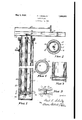
- Fig. 1 is a vertical transverse section through a lift embodying my nvention, as applied to the selective meansfor restricting rotation of the lift;
- Fig. 2 1s a transverse section taken on the line 2-2 in Fig. 1;
- Fig. 3 is a longitudinal section through the lower part of the lift, embodying my invention, as applied to a permanent rotation'restrictive means;
- Fig. 4 is a section taken on the line -44 in Fig. 3 and
- Fig. 5 is a top plan view on a reduced scale, of a lift showing selective rotative positions,
- This invention is shown in connection with a fluid operated lift, wherein shows a casing, which is adapted to be imbedded 1n i5 the ground, while 11 indicates a plunger 01' ram, which is mounted for reciprocation therein.
- the ram supports a head indicated in general at 12, which in turn supports trackways 13 upon which the vehicle may be positioned.
- the plunger is closed at the bottom by a head 14,
- fluid means for raising the plunger may be introduced into the space between the plunger and easing through a conduit 15.
- the plunger is limited in its vertical movement upward, by engagement of a shoulder 16 on the plunger with a stop 17 on the casing. Suitable packing is indicated at 18 to prevent leakage between the'casingand plunger.
- the present invention embodies means for selectively clamping or looking the trackway against rotation with reference to the casing, while still permitting vertical movement of the plunger or ram within the casing.
- the preferred means for accomplishing this feature embodies a disc like member 20, that is supported on the lower end of a rod 21 by members 22.
- the member is adapted to be clamped against the lower end of the plunger by operation of a locking member 23, which is threaded onto the upper end of the rod and outside the confines of the plunger.
- the rod extends through the lower plate 24 and is threaded to receive the member 23. Access to the last named member may be had through an opening 25 in the head for purposes of adjustment.
- the member 20 is preferably free to rotate on the rod 21, and is preferably provided with a forked lateral extension 26 that straddles a guide bar 27. Such bar is fastened onto the inner wall of the casing, and extends vertically from the stop 17 to the bottom of the casing.
- the member 20 is splined to the casing, and is adapted to be selectively clamped to the plunger. When so clamped, the plunger is free' to move vertically, but is restricted against rotation with reference to the casing. 4
- a sleeve 30 which surrounds the pipe 21, and is surrounded with packing means 31 at the upper end thereof.
- the lower end of the sleeve may be welded onto the head 14, and the rod may be locked against rotation with reference to the sleeve by a key 32.
- a device for permanently locking the plunger against rotation comprises the utilization of a guide bar 40 that extends vertically on the inner face of the casing, and a forked portion 41 that extends around the guide bar.
- Such forked portion may comprise part of the annular member 42 that normally is positioned adjacent the lower portion of the plunger and acts as a stop to limit the upward movement thereof.
- An advantage of my invention is the fact that the means for restricting rotation of the plunger, with reference to the casing, is mounted within the casing, where it does not obstruct the space beneath the lift and does not require additional openings within the ground.
- a further advantage of my invention is. the fact that the plunger may be locked selectively against rotation after having been rotated to a desired position, and
- the member for controlling the selective characteristic is conveniently located in an accessible position outside the plunger.
- a vehicle lift comprising in combination, a casing adapted to be imbedded within the ground, aplunger mounted for reciprocation therein, means inside the casing and outside the plunger for permitting reciprocation, but preventing rotation of the plunger withreference to the casing, and a member extending through the center of the plunger and operable from a point outside the plunger for selectively controlling said means.
- a vehicle lift comprising in combination, a casing adapted to'be imbedded within the ground, a plunger mounted for-reciprocation and rotation therein, and means including a member positioned adjacent the center of the plunger for selectively locking the plunger against rotation with reference to the casing.
- a vehicle lift comprising in combination, a casing adapted to be imbedded within the ground, a plunger mounted for reciprocation and rotation therein, and means including a member positioned adjacent the center of the plunger and extending therethrough, for selectively locking the plunger against rotation with reference to the casing.
- a vehicle lift comprising in combina tion, a casing, a plunger mounted for reciprocation and rotation therein, a trackway supported on the plunger, and means for selectively locking the plunger against rotation with reference to the casing.
- a vehicle lift comprising in combination, a casing adapted to be imbedded within the ground, a member mounted for reciprocation therein, a vehicle trackway supported .on said member, and connected therewith,
- trackway may be rotated with reference to the casing, and means including one member outside and another member inside the casing, and cooperating therewith for selectively locking the plunger against rotation with reference to the casing.
- a vehicle lift comprisin in combination, a casing adapted to be imbedded within the ground, a plunger mounted for reciprocation and rotation therein, a guide bar rigidly mounted on the inner wall of the casing, a forked member engaging theguide bar, and means outside the plunger for selectively clamping the forked member to the plunger, whereby the plunger is permitted to move vertically, but is restricted against rotation with reference to the casing.
- a vehicle lift comprising in combination, a casing adapted to be imbedded within the ground, a plunger mounted for reciprocation and rotation therein, a guide bar rigidly mounted on the inner wall of the casing, a forked member engaging the guide bar, and means for selectively clamping the plunger against rotation with reference to the casing, while permitting reciprocation within the casing, said means including a member extending through the plunger and into the space between the plunger and casing, and other means outside the plunger for selectively locking the plunger against rotation with reference to the casing.
- a vehicle lift comprising in combination, a casing adapted to be embedded within the ground, a vehicle supporting member mounted for reciprocation and rotation with reference to the casing, a locking device associated with themember and means operable from a point outside the member for selectively locking it against rotation only with reference to the casing.
- PAUL I SCHULTZ.
Landscapes
- Life Sciences & Earth Sciences (AREA)
- Engineering & Computer Science (AREA)
- Geology (AREA)
- Mechanical Engineering (AREA)
- Structural Engineering (AREA)
- Devices For Conveying Motion By Means Of Endless Flexible Members (AREA)
Description
P. I. SCHULTZ VEHICLE LIFT May 3, 1932.
Filed Dec. 11, 1930 I Fi .1 I
Patented May 3, 1932 UNITED STATES PATENT OFFICE- PAUL I. SCHULTZ, OF CLEVELANILOHIO, ASSIGNOR TO THE UNITED STATES AIR COM- PRESSOR COMPANY, OF CLEVELAND, OHIO, A CORPORATION OF OHIO VEHICLE LIFT Application filed December 11, 1930. Serial No. 501,555.
This invention relates to power actuated lifts that are used for elevating a motor vehicle, such as for greasing, oiling and repairing purposes, and particularly to lifts of the 5 fluid actuated and rotating type.
In many instances, it is desirable that the lifts be free to move vertically, and yet be held against rotation, particularly where they are arranged within an enclosed greasing sta- ,0 tion. Accordingly, an object of the present invention is to make a lift, which employs acentrally disposed vertically movable ram and yet restricts rotation thereof. In this connection, my invention embodies means .5 that may effect permanent restriction against rotation, or selective restriction in accordance with the demand at the place of use.
In the drawings, Fig. 1 is a vertical transverse section through a lift embodying my nvention, as applied to the selective meansfor restricting rotation of the lift; Fig. 2 1s a transverse section taken on the line 2-2 in Fig. 1; Fig. 3 is a longitudinal section through the lower part of the lift, embodying my invention, as applied to a permanent rotation'restrictive means; Fig. 4 is a section taken on the line -44 in Fig. 3, and Fig. 5 is a top plan view on a reduced scale, of a lift showing selective rotative positions,
30 which may be obtained with the form of invention illustrated in Fig. 1.
This invention is shown in connection with a fluid operated lift, wherein shows a casing, which is adapted to be imbedded 1n i5 the ground, while 11 indicates a plunger 01' ram, which is mounted for reciprocation therein. The ram supports a head indicated in general at 12, which in turn supports trackways 13 upon which the vehicle may be positioned. In the form shown in Fig. 1, the plunger is closed at the bottom by a head 14,
' and fluid means for raising the plunger may be introduced into the space between the plunger and easing through a conduit 15.
-- Under the normal operation of the lift, the plunger is limited in its vertical movement upward, by engagement of a shoulder 16 on the plunger with a stop 17 on the casing. Suitable packing is indicated at 18 to prevent leakage between the'casingand plunger.
The present invention is not concerned with I the details of such construction wherefore, such features are merely indicated in general to show, an operative lift.
The present invention, as is illustrated in Fig. 1, embodies means for selectively clamping or looking the trackway against rotation with reference to the casing, while still permitting vertical movement of the plunger or ram within the casing. The preferred means for accomplishing this feature embodies a disc like member 20, that is supported on the lower end of a rod 21 by members 22. The member is adapted to be clamped against the lower end of the plunger by operation of a locking member 23, which is threaded onto the upper end of the rod and outside the confines of the plunger. To this end, the rod extends through the lower plate 24 and is threaded to receive the member 23. Access to the last named member may be had through an opening 25 in the head for purposes of adjustment.
The member 20 is preferably free to rotate on the rod 21, and is preferably provided with a forked lateral extension 26 that straddles a guide bar 27. Such bar is fastened onto the inner wall of the casing, and extends vertically from the stop 17 to the bottom of the casing. Thus in effect, the member 20 is splined to the casing, and is adapted to be selectively clamped to the plunger. When so clamped, the plunger is free' to move vertically, but is restricted against rotation with reference to the casing. 4
To guard against leakage of fluid into the plunger, I utilize a sleeve 30, which surrounds the pipe 21, and is surrounded with packing means 31 at the upper end thereof. The lower end of the sleeve may be welded onto the head 14, and the rod may be locked against rotation with reference to the sleeve by a key 32.
In Figs. 3 and 4:, I have shown a device for permanently locking the plunger against rotation. In the preferred arrangement, such device comprises the utilization of a guide bar 40 that extends vertically on the inner face of the casing, and a forked portion 41 that extends around the guide bar. Such forked portion may comprise part of the annular member 42 that normally is positioned adjacent the lower portion of the plunger and acts as a stop to limit the upward movement thereof.
An advantage of my invention is the fact that the means for restricting rotation of the plunger, with reference to the casing, is mounted within the casing, where it does not obstruct the space beneath the lift and does not require additional openings within the ground. A further advantage of my invention is. the fact that the plunger may be locked selectively against rotation after having been rotated to a desired position, and
\ that the member for controlling the selective characteristic is conveniently located in an accessible position outside the plunger.
I claim:
1. A vehicle lift comprising in combination, a casing adapted to be imbedded within the ground, aplunger mounted for reciprocation therein, means inside the casing and outside the plunger for permitting reciprocation, but preventing rotation of the plunger withreference to the casing, and a member extending through the center of the plunger and operable from a point outside the plunger for selectively controlling said means.
2. A vehicle lift comprising in combination, a casing adapted to'be imbedded within the ground, a plunger mounted for-reciprocation and rotation therein, and means including a member positioned adjacent the center of the plunger for selectively locking the plunger against rotation with reference to the casing.
3. A vehicle lift comprising in combination, a casing adapted to be imbedded within the ground, a plunger mounted for reciprocation and rotation therein, and means including a member positioned adjacent the center of the plunger and extending therethrough, for selectively locking the plunger against rotation with reference to the casing.
4. A vehicle lift comprising in combina tion, a casing, a plunger mounted for reciprocation and rotation therein, a trackway supported on the plunger, and means for selectively locking the plunger against rotation with reference to the casing.
- 5. A vehicle lift comprising in combination, a casing adapted to be imbedded within the ground, a member mounted for reciprocation therein, a vehicle trackway supported .on said member, and connected therewith,
whereby the trackway may be rotated with reference to the casing, and means including one member outside and another member inside the casing, and cooperating therewith for selectively locking the plunger against rotation with reference to the casing.
6. A vehicle lift comprisin in combination, a casing adapted to be imbedded within the ground, a plunger mounted for reciprocation and rotation therein, a guide bar rigidly mounted on the inner wall of the casing, a forked member engaging theguide bar, and means outside the plunger for selectively clamping the forked member to the plunger, whereby the plunger is permitted to move vertically, but is restricted against rotation with reference to the casing.
7. A vehicle lift comprising in combination, a casing adapted to be imbedded within the ground, a plunger mounted for reciprocation and rotation therein, a guide bar rigidly mounted on the inner wall of the casing, a forked member engaging the guide bar, and means for selectively clamping the plunger against rotation with reference to the casing, while permitting reciprocation within the casing, said means including a member extending through the plunger and into the space between the plunger and casing, and other means outside the plunger for selectively locking the plunger against rotation with reference to the casing.
" '8. A vehicle lift, comprising in combination, a casing adapted to be embedded within the ground, a vehicle supporting member mounted for reciprocation and rotation with reference to the casing, a locking device associated with themember and means operable from a point outside the member for selectively locking it against rotation only with reference to the casing.
In testimony-whereof, I hereunto afiix my signature.
PAUL I. SCHULTZ.
Priority Applications (1)
| Application Number | Priority Date | Filing Date | Title |
|---|---|---|---|
| US501555A US1856660A (en) | 1930-12-11 | 1930-12-11 | Vehicle lift |
Applications Claiming Priority (1)
| Application Number | Priority Date | Filing Date | Title |
|---|---|---|---|
| US501555A US1856660A (en) | 1930-12-11 | 1930-12-11 | Vehicle lift |
Publications (1)
| Publication Number | Publication Date |
|---|---|
| US1856660A true US1856660A (en) | 1932-05-03 |
Family
ID=23994038
Family Applications (1)
| Application Number | Title | Priority Date | Filing Date |
|---|---|---|---|
| US501555A Expired - Lifetime US1856660A (en) | 1930-12-11 | 1930-12-11 | Vehicle lift |
Country Status (1)
| Country | Link |
|---|---|
| US (1) | US1856660A (en) |
Cited By (3)
| Publication number | Priority date | Publication date | Assignee | Title |
|---|---|---|---|---|
| US2426447A (en) * | 1942-08-11 | 1947-08-26 | John N Gladden | Shock absorber |
| US2638316A (en) * | 1950-01-14 | 1953-05-12 | Byron Jackson Co | Power unit for a well pipe slip assembly |
| DE946744C (en) * | 1953-09-06 | 1956-08-02 | Franz Hoernstein | Hydraulic-pneumatic lifting platform |
-
1930
- 1930-12-11 US US501555A patent/US1856660A/en not_active Expired - Lifetime
Cited By (3)
| Publication number | Priority date | Publication date | Assignee | Title |
|---|---|---|---|---|
| US2426447A (en) * | 1942-08-11 | 1947-08-26 | John N Gladden | Shock absorber |
| US2638316A (en) * | 1950-01-14 | 1953-05-12 | Byron Jackson Co | Power unit for a well pipe slip assembly |
| DE946744C (en) * | 1953-09-06 | 1956-08-02 | Franz Hoernstein | Hydraulic-pneumatic lifting platform |
Similar Documents
| Publication | Publication Date | Title |
|---|---|---|
| US2435470A (en) | Pump | |
| US1856660A (en) | Vehicle lift | |
| US1548559A (en) | Fluid-pressure jack | |
| US1683911A (en) | Water supply for automobile radiators | |
| US2146403A (en) | Bumper jack | |
| US1624151A (en) | Hydraulic jack | |
| US2583923A (en) | Hydraulic jack | |
| US2288511A (en) | Automobile lift | |
| US2157480A (en) | Magnetic valve | |
| US2243758A (en) | Unitary guiding and latching means for automobile hoods | |
| US2283593A (en) | Hydraulic bumper jack | |
| US2002450A (en) | Cylinder cock | |
| US1763404A (en) | Hydraulic jack | |
| US1784116A (en) | Hydraulc jack | |
| US1815907A (en) | Elevator | |
| US2030332A (en) | Valve | |
| US2550882A (en) | Hoist safety valve | |
| US2451390A (en) | Hydraulic jack | |
| US2044699A (en) | Lifting jack | |
| US1903763A (en) | Hydraulic lifting mechanism | |
| US3377981A (en) | Level indicator | |
| US1846299A (en) | Automobile lift | |
| US2080114A (en) | Vehicle lift | |
| US1784553A (en) | Hydraulic jack | |
| US3140641A (en) | Vehicle lift apparatus |