US1856560A - Torch head - Google Patents
Torch head Download PDFInfo
- Publication number
- US1856560A US1856560A US496967A US49696730A US1856560A US 1856560 A US1856560 A US 1856560A US 496967 A US496967 A US 496967A US 49696730 A US49696730 A US 49696730A US 1856560 A US1856560 A US 1856560A
- Authority
- US
- United States
- Prior art keywords
- torch
- torches
- spindle
- bearing member
- bearing
- Prior art date
- Legal status (The legal status is an assumption and is not a legal conclusion. Google has not performed a legal analysis and makes no representation as to the accuracy of the status listed.)
- Expired - Lifetime
Links
- 239000007789 gas Substances 0.000 description 12
- 238000003466 welding Methods 0.000 description 8
- 210000002445 nipple Anatomy 0.000 description 4
- QFXZANXYUCUTQH-UHFFFAOYSA-N ethynol Chemical group OC#C QFXZANXYUCUTQH-UHFFFAOYSA-N 0.000 description 3
- 230000001105 regulatory effect Effects 0.000 description 2
- 102000010029 Homer Scaffolding Proteins Human genes 0.000 description 1
- 108010077223 Homer Scaffolding Proteins Proteins 0.000 description 1
- QVGXLLKOCUKJST-UHFFFAOYSA-N atomic oxygen Chemical compound [O] QVGXLLKOCUKJST-UHFFFAOYSA-N 0.000 description 1
- 238000002485 combustion reaction Methods 0.000 description 1
- 230000001276 controlling effect Effects 0.000 description 1
- 238000010438 heat treatment Methods 0.000 description 1
- 229910052751 metal Inorganic materials 0.000 description 1
- 239000002184 metal Substances 0.000 description 1
- 150000002739 metals Chemical class 0.000 description 1
- 238000012986 modification Methods 0.000 description 1
- 230000004048 modification Effects 0.000 description 1
- 239000001301 oxygen Substances 0.000 description 1
- 229910052760 oxygen Inorganic materials 0.000 description 1
Images
Classifications
-
- B—PERFORMING OPERATIONS; TRANSPORTING
- B23—MACHINE TOOLS; METAL-WORKING NOT OTHERWISE PROVIDED FOR
- B23K—SOLDERING OR UNSOLDERING; WELDING; CLADDING OR PLATING BY SOLDERING OR WELDING; CUTTING BY APPLYING HEAT LOCALLY, e.g. FLAME CUTTING; WORKING BY LASER BEAM
- B23K7/00—Cutting, scarfing, or desurfacing by applying flames
- B23K7/005—Machines, apparatus, or equipment specially adapted for cutting curved workpieces, e.g. tubes
- B23K7/006—Machines, apparatus, or equipment specially adapted for cutting curved workpieces, e.g. tubes for tubes
Definitions
- My invention relates to machines for working metals with heat, and especially to devices for operating and regulating the heaters or torches, such as combustion torches and electr1c arcs which are used in the machlnes.
- Another object of my invention is to provide means within convenient control of one operator for accurately regulating longitudiml and rotative movements of torches as well as the degree of heat supplied by torches which are adapted to heat restricted areas of the articles worked upon,
- Figure 2 is a sectional view taken approximately along the line II-II of Fig. 1.
- a relatively fixed 80 pipe A is fixedly clamped in the machine by the clamp 1 which is threadably secured in the yoke 3.
- the yoke 3 is secured to the end transverse frame member 5 by the bolts 7.
- the frame has an intermediate transverse 85 frame member 9 on which an intermediate yoke 11 is secured bythe bolts 12.
- the frame of the machine is formed by bolting the transverse frame members to longitudinal frame members 13 by the bolts 15.
- the intermediate yoke 9 carries cylindrical projecting collars 17 and 18 which are bored to align the pipe '13 with the pipe A and through which the pipe B is capable of sliding longitudinally.
- the collar 18 constitutes a hollow spindle for a bearing 19 which ismounted to rotate and to slide longi 'tudinally on the external surface of the spindle and constitutes one member of a torch head.
- the torch head comprises the oxy-acetylene torches 21, a torch ring 23 adapted to support the torches and conduct gases to the torches, one or more gas mixers 25 which communicate with the torch ring and with gas supply pipes, a reel for the gas supply pipes and the supporting bearing 19.
- the tips of the torches are desirably spaced I from the end of spindle 18 and from the outer face of the hose reel drum by mounting the mixers 25 and the semicircular sections of the torch ring 23 on the brackets 29, but the torch ring 23 and the mixers 25 -may be mounted directly on the outer face hoses at the outer ends of passages 41 and 43.
- the passages 41 and 43 are bored through the cylindrical portion 32 of the hose reel drum gases from sources of supply to the nipples v .37 and 39 which nipples are connected to the and they extend through the outer face of the drum.
- Oxygen and gas are conducted from the nipples 37 and 39 to each of the mixers 25 through pipes 47 and 49 which .are connected to the mixers and the nipples by means of suitable connections. B y attaching the torch ring and the mixers directly to the hose reel drum, the brackets 29 and the pipes 47 and 49 may be omitted.
- the torches 21 are dis osed so that alternate torches are directed o liquely onto the end face of the pipe A and the other torches are directed obliquely onto the confronting face of the pipe B but the torch tips can e directed in other directions.
- the torch tips 51 and 53 are desirably equally spacedon a circumference which is somewhat larger than the outer circumferences of the pipes to be welded so that longitudinal movements of" the torches and the pipes do not interfere with each other.
- a space of about one-half inch between the 7 tips and the outer. walls of pipes A and B is usually suflicient but the space may be varied.
- obliquely disposed gas tips may be directed so that the angles between the flames are about 50 but the obliquity of the flames can be varied.
- the flames of each set of torches are preferably directed in opposite directions along the surface and toward the apex of the cone having its. axis approximately coinciding with the axis of the pipes to bewelded.
- An adjusting lever 57 having an operating handle 59 on its outer end, is pivoted on the desired angular movement around frame member 9 on bracket 61;
- the inner end of the lever 57 branches and the branches extend to approximately diametrically opposite points of the bearing 19.
- rollers 63- are mounted to 'turn on the shafts 65 and to bear on a circumferential flange,
- a head for supporting and operating torches comprising a bearing member adapted for rotatable and longitudinal movement, a support for said bearing, a conduit-reel on the bearing member, means on the bearing member for supporting said torches, and. means engaging the bearing member to longitudinally actuate the bearing in either direction while the bearing is rotated.
- a head for supporting and operating torches comprising a support, a spindle on said support, a bearing member adapted for rotatable and longitudinal movement on said spindle, a plurality of circumferential flanges on the bearing member, and means pivoted on the support and engaging at least one of said flanges to actuate the bearing member longitudinally in either direction while the bearing member is rotated.
- a head for supporting and operating torches comprising av-bearing member adapted for rotatable and longitudinal movement on a fixed spindle, means on the bearing member to reel a supply conduit, a torch ring supported on saidbearing member. and conducting means rotatable with said bearing and reel to provide communication between said conduit and said torch ring.
- a head for supporting and operating torches comprising a hollow spindle adapted.
- abearing member adapted for rotatable and longitudinal-movement on said spindle, spaced flanges on the bearing member to provide a reeling drum for conduits, means to secure the conduits to the drum, a torch ring supported on the drum and a plurality of circumferentially disposed torch means mounted on said ring, andcommunieating conduits extending through the drum and then to the torch means.
- a head for supporting and operating torches comprising aihollow spindle adapted to receive an article, to be worked uponby torches, a bearing member'adapted for rotatable and lon 'tudinal movement on said.
- a torch head comprising a spindle, a bearing member adapted for rotatable and longitudinal movement on said spindle, a.
- flanged drum on the bearing member having passages extending through the body of the drum and terminating in one face of the drum, a plurality of torch means having tips spaced from the drum and arranged circumferentially, means to mount the tips on the drum, and means to supply gases from sources of supply to the tips through said passages.
- a torch head comprising a spindle, a bearing member adapted for rotatable and longitudinal movement on said spindle, a plurality of flanges on the bearing member, means engaging at least one of said flanges to actuate the bearing member longitudinally in either direction while said bearing member isrotated, a plurality of torch means having tipsspaced from the flanges and ar-.
- a torch head comprising a spindle, a bearing member adapted for rotatable and longitudinal movement on said spindle, a hose reel and torch means supported on the hearing, said torch means having tips which are spaced from the hose reel and arranged circumferentially, a circumferential guide flange on the bearing member, and a lever pivoted on the journalled support and having bearing means at one end to engage the guideflange and actuate the torches longitudinally while they are rotated.
- a torch 'head comprising a support which is adapted to support an article which is to be worked upon by'torches, a spindle on said support, a bearing member adapted for revolving and longitudinal movement on said spindle, torch means supported on the bearing member, said torch means having tips spaced on a circumference around the article which is to be worked, means to conduct gases to the torch means while the torches are rotated, flanged portions on the bearing memher, and means to engage at least one of said I flanges to actuate the torches longitudinally while they are rotated.
- a welding torch head adapted to weld together the end edges of two pieces of ipe, said head comprising a hollow spindle a apted to receive thepipe to be welded; a bearing member rotatably mounted on said spindle; a ring of torches carried by said bearin member and surrounding the axis of said spindle, said torches having discharge assages therein adapted to direct wel 'ng flames in opposite lengthwise directions of the pipe upon the end edges of the pipe to be welded and obliquely to the plane of rotation of said torches.
- a weldin torch head adapted to weld together the en edges of two pieces of pipe, said head comprising a hollow s indle adapted to receive the pipe to be we ded; a hearing member rotatably mounted on said spindle; a ring of torches carried by said bearing
Landscapes
- Engineering & Computer Science (AREA)
- Mechanical Engineering (AREA)
- Arc Welding In General (AREA)
Description
H. W. JONES May 3, 1932.
TORCH HEAD Filed Nov. 20, 19:50 2 Sheets-Shet H. w.. JONES 1,856,560
TORCH HEAD May 3; 1932.
Filed NOV. 20. 1950 2 Sheets-Sheet 2 NVENTOR 1 AoRNEYs.
Patented May 3, 1932 UNITED STATES PATENT OFFICE HOMER W. JONES, OF WILLLAMSVTLLE, NEW YORK, AS SIGNOB TO THE LINDE AIR PRODUCTS COMPANY, A CORPORATION OF OHIO TORCH HEAD Application filed November 20, 1930. Serial No. 496,967.
My invention relates to machines for working metals with heat, and especially to devices for operating and regulating the heaters or torches, such as combustion torches and electr1c arcs which are used in the machlnes.
It is among the objects of my invention to provide a heating device which can be given any desired rotative or longitudinal movement about a pipe or other article upon which work is to be done while the heat is being applied.
Another object of my invention is to provide means within convenient control of one operator for accurately regulating longitudiml and rotative movements of torches as well as the degree of heat supplied by torches which are adapted to heat restricted areas of the articles worked upon,
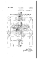
Other objects of my invention will be apparent from the following description of a pipe welding machine which employs oxyacetylene torches. The description refers to thle (irawings constituting a part hereof, in w 10 Figure 1 is a top plan view of a portion of a butt-welding machine, and
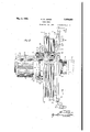
Figure 2 is a sectional view taken approximately along the line II-II of Fig. 1.
As shown in Figure 1, a relatively fixed 80 pipe A is fixedly clamped in the machine by the clamp 1 which is threadably secured in the yoke 3. The yoke 3 is secured to the end transverse frame member 5 by the bolts 7. The frame has an intermediate transverse 85 frame member 9 on which an intermediate yoke 11 is secured bythe bolts 12.
Devices for guidin and clamping a relatively movable pipe in endwise relationship to pipe A and for controlling various 1 9 forward and backward movements .of the pipe B to produce a welding of the ends of the pipes are mounted on and between the yoke 9, and an end yoke. The pipe vcontrollin device, the extreme end yoke andthe en transverse frame member are not shown.
The frame of the machine is formed by bolting the transverse frame members to longitudinal frame members 13 by the bolts 15.
The intermediate yoke 9 carries cylindrical projecting collars 17 and 18 which are bored to align the pipe '13 with the pipe A and through which the pipe B is capable of sliding longitudinally. The collar 18 constitutes a hollow spindle for a bearing 19 which ismounted to rotate and to slide longi 'tudinally on the external surface of the spindle and constitutes one member of a torch head. v
The torch head comprises the oxy-acetylene torches 21, a torch ring 23 adapted to support the torches and conduct gases to the torches, one or more gas mixers 25 which communicate with the torch ring and with gas supply pipes, a reel for the gas supply pipes and the supporting bearing 19.
I prefer to use two gas mixers 25 and to use a torch ring comprising two semi-circular parts with conduits or bores 27 extending therethrough to the ends of each of the, semicircular parts, but the torch ring may consist of one or more arts and one or more mixers can be used. arious arrangements of the bore 27 in the torch ring can be usedl There maybe as many parts of the bore '27 as there are torches, there being at least as many mixers as there are bores.
The tips of the torches are desirably spaced I from the end of spindle 18 and from the outer face of the hose reel drum by mounting the mixers 25 and the semicircular sections of the torch ring 23 on the brackets 29, but the torch ring 23 and the mixers 25 -may be mounted directly on the outer face hoses at the outer ends of passages 41 and 43. The passages 41 and 43 are bored through the cylindrical portion 32 of the hose reel drum gases from sources of supply to the nipples v .37 and 39 which nipples are connected to the and they extend through the outer face of the drum. Oxygen and gas are conducted from the nipples 37 and 39 to each of the mixers 25 through pipes 47 and 49 which .are connected to the mixers and the nipples by means of suitable connections. B y attaching the torch ring and the mixers directly to the hose reel drum, the brackets 29 and the pipes 47 and 49 may be omitted.
According to one arrangement, the torches 21 are dis osed so that alternate torches are directed o liquely onto the end face of the pipe A and the other torches are directed obliquely onto the confronting face of the pipe B but the torch tips can e directed in other directions. The torch tips 51 and 53 are desirably equally spacedon a circumference which is somewhat larger than the outer circumferences of the pipes to be welded so that longitudinal movements of" the torches and the pipes do not interfere with each other.
A space of about one-half inch between the 7 tips and the outer. walls of pipes A and B is usually suflicient but the space may be varied.
For welding pipes which are cut ofi on a plane substantially perpendicular to the axis of the pipes, obliquely disposed gas tips may be directed so that the angles between the flames are about 50 but the obliquity of the flames can be varied. The flames of each set of torches are preferably directed in opposite directions along the surface and toward the apex of the cone having its. axis approximately coinciding with the axis of the pipes to bewelded. In butt-welding pipes, it is desirable to regulate the spacing of the ends of the pipes and the angle between the flames so that the flames will impinge obliquely on the confronting faces. of the pipes and reflect on opposing faces.
An adjusting lever 57 having an operating handle 59 on its outer end, is pivoted on the desired angular movement around frame member 9 on bracket 61; The inner end of the lever 57 branches and the branches extend to approximately diametrically opposite points of the bearing 19. On the inner ends of thebranches of lever 57 rollers 63- are mounted to 'turn on the shafts 65 and to bear on a circumferential flange,
as for example the flange near the inner end of the bearing 19. Since 'therollers 63 travel on the opposite confronting faces of the flange 55, it is evident that longitudinal movement may be given to the torch head'by locating the lever so that the rollers will operate on the opposing faces-of the abovedescribed circum erential flanges. With this arrangement the torches may be given any the pipes, the hose may be reeled on or off and the torch tips may be adjusted longitudinally of the' while'the torch tips are replpes before 0 volved.
The invention has been described with reference' to a welding machine which employs oxy-acetylene torches but it is to be understood that I do not intend to s ecifically limit my invention to the described machine since the invention may be embodied in machines which use other kinds of torches and it may be embodied in machines which are used for other purposes than weldin Various modifications have been pointe out but it is evident that other modlfications can be made in the described welding head without departing from the invention,/and I- wish the invention to be limited only by the limitations im-' posed by the prior art and by the invention defined in the annexed claims.
1. A head for supporting and operating torches comprising a bearing member adapted for rotatable and longitudinal movement, a support for said bearing, a conduit-reel on the bearing member, means on the bearing member for supporting said torches, and. means engaging the bearing member to longitudinally actuate the bearing in either direction while the bearing is rotated.
2. A head for supporting and operating torches comprising a support, a spindle on said support, a bearing member adapted for rotatable and longitudinal movement on said spindle, a plurality of circumferential flanges on the bearing member, and means pivoted on the support and engaging at least one of said flanges to actuate the bearing member longitudinally in either direction while the bearing member is rotated.
3. A head for supporting and operating torches comprising av-bearing member adapted for rotatable and longitudinal movement on a fixed spindle, means on the bearing member to reel a supply conduit, a torch ring supported on saidbearing member. and conducting means rotatable with said bearing and reel to provide communication between said conduit and said torch ring.
4. A head for supporting and operating torches comprising a hollow spindle adapted. 3
to receive an article to be worked upon by "torches,
abearing member adapted for rotatable and longitudinal-movement on said spindle, spaced flanges on the bearing member to provide a reeling drum for conduits, means to secure the conduits to the drum, a torch ring supported on the drum and a plurality of circumferentially disposed torch means mounted on said ring, andcommunieating conduits extending through the drum and then to the torch means. a v
5. A head for supporting and operating torches comprising aihollow spindle adapted to receive an article, to be worked uponby torches, a bearing member'adapted for rotatable and lon 'tudinal movement on said.
spindle, space flanges on the bearing memher to provide a reeling drum for conduits, means to secure the conduits to the drum a torch. ring supported onthe drum and a plu- III rality of torch means mounted on said ring and disposed on a circumference outside of the article to be worked upon, and communicating conduits extending through the drum and then to the torch means.
6. A torch head comprising a spindle, a bearing member adapted for rotatable and longitudinal movement on said spindle, a.
flanged drum on the bearing member having passages extending through the body of the drum and terminating in one face of the drum, a plurality of torch means having tips spaced from the drum and arranged circumferentially, means to mount the tips on the drum, and means to supply gases from sources of supply to the tips through said passages.
7. A torch head comprising a spindle, a bearing member adapted for rotatable and longitudinal movement on said spindle, a plurality of flanges on the bearing member, means engaging at least one of said flanges to actuate the bearing member longitudinally in either direction while said bearing member isrotated, a plurality of torch means having tipsspaced from the flanges and ar-.
ranged circumferentially, means to mount the torch means on a portion of the bearing member, said bearing member having bores extending through a portion thereof, flexible means capable of being reeled on the bearing means to conduct gases to said bores, and
means to conduct gases from the bores to the" torch means.
8. A torch head comprising a spindle, a bearing member adapted for rotatable and longitudinal movement on said spindle, a hose reel and torch means supported on the hearing, said torch means having tips which are spaced from the hose reel and arranged circumferentially, a circumferential guide flange on the bearing member, and a lever pivoted on the journalled support and having bearing means at one end to engage the guideflange and actuate the torches longitudinally while they are rotated.
9. A torch 'head comprising a support which is adapted to support an article which is to be worked upon by'torches, a spindle on said support, a bearing member adapted for revolving and longitudinal movement on said spindle, torch means supported on the bearing member, said torch means having tips spaced on a circumference around the article which is to be worked, means to conduct gases to the torch means while the torches are rotated, flanged portions on the bearing memher, and means to engage at least one of said I flanges to actuate the torches longitudinally while they are rotated.
10. A welding torch head adapted to weld together the end edges of two pieces of ipe, said head comprising a hollow spindle a apted to receive thepipe to be welded; a bearing member rotatably mounted on said spindle; a ring of torches carried by said bearin member and surrounding the axis of said spindle, said torches having discharge assages therein adapted to direct wel 'ng flames in opposite lengthwise directions of the pipe upon the end edges of the pipe to be welded and obliquely to the plane of rotation of said torches.
11. A weldin torch head adapted to weld together the en edges of two pieces of pipe, said head comprising a hollow s indle adapted to receive the pipe to be we ded; a hearing member rotatably mounted on said spindle; a ring of torches carried by said bearing
Priority Applications (1)
| Application Number | Priority Date | Filing Date | Title |
|---|---|---|---|
| US496967A US1856560A (en) | 1930-11-20 | 1930-11-20 | Torch head |
Applications Claiming Priority (1)
| Application Number | Priority Date | Filing Date | Title |
|---|---|---|---|
| US496967A US1856560A (en) | 1930-11-20 | 1930-11-20 | Torch head |
Publications (1)
| Publication Number | Publication Date |
|---|---|
| US1856560A true US1856560A (en) | 1932-05-03 |
Family
ID=23974915
Family Applications (1)
| Application Number | Title | Priority Date | Filing Date |
|---|---|---|---|
| US496967A Expired - Lifetime US1856560A (en) | 1930-11-20 | 1930-11-20 | Torch head |
Country Status (1)
| Country | Link |
|---|---|
| US (1) | US1856560A (en) |
Cited By (1)
| Publication number | Priority date | Publication date | Assignee | Title |
|---|---|---|---|---|
| FR2537482A1 (en) * | 1982-12-09 | 1984-06-15 | Tachikawa Spring Co | ANGLE WELDING APPARATUS |
-
1930
- 1930-11-20 US US496967A patent/US1856560A/en not_active Expired - Lifetime
Cited By (1)
| Publication number | Priority date | Publication date | Assignee | Title |
|---|---|---|---|---|
| FR2537482A1 (en) * | 1982-12-09 | 1984-06-15 | Tachikawa Spring Co | ANGLE WELDING APPARATUS |
Similar Documents
| Publication | Publication Date | Title |
|---|---|---|
| US4306134A (en) | Arc welding pipe apparatus | |
| US3330021A (en) | Pipe aligning tool | |
| US4791270A (en) | Gas tungsten arc welding machine with infinite rotating welding head and torch tilt | |
| US9682448B1 (en) | Apparatus for torch cutting large pipe | |
| US6737608B2 (en) | Automated welding device for the buildup of material | |
| US2845038A (en) | Seam guide assembly | |
| US2054375A (en) | Welding apparatus | |
| US1856560A (en) | Torch head | |
| US2868953A (en) | Rotatable arc welding tool | |
| CN105665893A (en) | Consumable electrode gas shielded welding pipe plate welding machine | |
| US1852412A (en) | Pipe cutter | |
| CN209754263U (en) | Thick wall stainless steel pipeline cutting device | |
| US1351846A (en) | Circle-guide for oxyacetylene-torches | |
| US1692924A (en) | Burner holder | |
| US3125670A (en) | hawthorne | |
| US2061442A (en) | Pipe cutter | |
| US2985746A (en) | Butt-welding apparatus | |
| US2906851A (en) | Welding apparatus for use with flexible dam | |
| CN115446430A (en) | Pipeline assembly welding integrated machine head | |
| US1775667A (en) | Pipe-cutting machine | |
| US3406271A (en) | Impedor for a tube mill | |
| US3483353A (en) | Welding apparatus | |
| CN212122076U (en) | Petroleum pipeline laser electric arc hybrid welding device | |
| US2041913A (en) | Protable welding machine | |
| US2966576A (en) | Welding and work tool mounting apparatus |