US185656A - Improvement in automatic steam-boiler feeders - Google Patents
Improvement in automatic steam-boiler feeders Download PDFInfo
- Publication number
- US185656A US185656A US185656DA US185656A US 185656 A US185656 A US 185656A US 185656D A US185656D A US 185656DA US 185656 A US185656 A US 185656A
- Authority
- US
- United States
- Prior art keywords
- pipe
- reservoir
- water
- boiler
- steam
- Prior art date
- Legal status (The legal status is an assumption and is not a legal conclusion. Google has not performed a legal analysis and makes no representation as to the accuracy of the status listed.)
- Expired - Lifetime
Links
- XLYOFNOQVPJJNP-UHFFFAOYSA-N water Substances O XLYOFNOQVPJJNP-UHFFFAOYSA-N 0.000 description 102
- 210000003141 Lower Extremity Anatomy 0.000 description 8
- 238000009833 condensation Methods 0.000 description 8
- 230000005494 condensation Effects 0.000 description 8
- 238000010276 construction Methods 0.000 description 8
- 239000000203 mixture Substances 0.000 description 8
- 238000004140 cleaning Methods 0.000 description 4
- 239000002184 metal Substances 0.000 description 4
- 239000000615 nonconductor Substances 0.000 description 4
- 229920001195 polyisoprene Polymers 0.000 description 4
- 230000001105 regulatory Effects 0.000 description 4
- 239000007921 spray Substances 0.000 description 4
- 239000002023 wood Substances 0.000 description 4
- 230000000875 corresponding Effects 0.000 description 2
- 230000001627 detrimental Effects 0.000 description 2
- 238000010438 heat treatment Methods 0.000 description 2
- 230000004941 influx Effects 0.000 description 2
- 239000000463 material Substances 0.000 description 2
- 230000002028 premature Effects 0.000 description 2
- 230000000717 retained Effects 0.000 description 2
Images

Classifications
-
- F—MECHANICAL ENGINEERING; LIGHTING; HEATING; WEAPONS; BLASTING
- F22—STEAM GENERATION
- F22D—PREHEATING, OR ACCUMULATING PREHEATED, FEED-WATER FOR STEAM GENERATION; FEED-WATER SUPPLY FOR STEAM GENERATION; CONTROLLING WATER LEVEL FOR STEAM GENERATION; AUXILIARY DEVICES FOR PROMOTING WATER CIRCULATION WITHIN STEAM BOILERS
- F22D11/00—Feed-water supply not provided for in other main groups
- F22D11/02—Arrangements of feed-water pumps
- F22D11/06—Arrangements of feed-water pumps for returning condensate to boiler
Definitions
- NICOLAS YAGN ST. PETERSBURG, RUSSIA, ASSIGNOR TO SALLY OOHNFELD, OF DRESDEN, GERMANY.
- the invention has for its object improvements in the construction of the hereinafter described self'acting apparatus for feeding steam-boilers with water, which is in the position to replace advantageously all hithertoused apparatuses for this purpose.
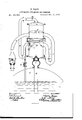
- this new self -acting feeding apparatus is shown in vertical section in annexed drawing.
- -It is composed of two metal reservoirs, cylindrical or otherwise shaped, R and B, one of which, R, is placed vertically above the other, R.
- R metal reservoirs
- R and B one of which, R
- R is placed vertically above the other, R.
- the bottom of the reservoir R and and the lid of the reservoir R are made to be taken off.
- caoutchouc rings may be placed between the borders of the bottom of R and of the lid of 1%, and the flanges O O of both reservoirs.
- the said flanges and borders, with the caoutchouc rings inserted in between them, are tightly screwed together by means of screw-bolts a a.
- the space 0 between the two reservoirs is filled up by a cushion of wood or other material, which is a non-conductor of heat.
- the reservoirs R and B. communicate with each other by means of the bent pipes B and C, the lower bend of the pipe B being placed on a level with the bottom of the reservoir R, while the lower bend of the pipe 0 is placed below this bottom.
- the pipe (J communicates with the lower part of the reservoir R by means of the short pipe d.
- the opening 3 is made in the side of the pipe 0, exactly opposite the pipe d.
- the opening 3! is closed by means of a screw, Y.
- an obturator or valve in the reservoir R to keep the orifice of the pipe B shut.
- This valve is provided with a float, T, and turning on the pivot U. The purport of this valve is to prevent any premature and therefore detrimental circulation of the water in the feeding apparatus, as will be explained further below.
- an opening, X At the topmost point of the self-acting feeding apparatus there is an opening, X, which can be closed either by means of a screw or a valve, or some other corresponding appliances. This opening is to let the air escape out of the feeding apparatus at the beginning of its being filled with Water. During all the time that the feeding apparatus is working this opening remains closed.
- W is a float in the reservoir R with a central hole, V, the diameter of the float being a little less than the inside diameter of the reservoir itself.
- A is a feeding-pipe communicating the reservoir R with a well or other cistern, which contains the alimentary water.
- This pipe is provided with one or two valves, f, of any suitable shape, giving way to the water from the well to the reservoir R, but preventing its passing vice versa.
- an ordinary forcing-pump is used for filling the boiler beforehand, and for cleaning the same, it can be advantageously connected with the pipe A to fill the self-acting feeding apparatus beforehand with water. In the contrary case the filling can be done through the aperture X.
- the reservoir R is provided with a pipe, g, which passes through the side of the boiler D, and terminates there at the height at which the water is to be kept in the boiler.
- the pipe g is furnished with a screw, K, used to diminish or regulate at will the passage of steam through it.
- This screw K may be replaced either by a suitable tap or sliding valve.
- the reservoir R is provided with a valve-box, h, having a valve, l, of any suitable construction, opening itself downward.
- the valve-box h is connected by means of a coupling-box, i, with the pipe E descending near to the bottom of boiler, so that the lower end of the pipe is continually under water.
- the valve 1 lets the Water pass freely from the reservoir B into the boiler D, but prevents it passing in the opposite direction.
- the above-described self-acting feeding apparatus may be placed immediately above the boiler, or at its side at some distance from it, which is preferable, as so placed it will not be. exposed so much to the influence of beat all ways existing above boilers. In this case the whole length of the pipe g must incline toward the boiler.
- the working of the self-acting feeding apparatus is as follows: Supposing the whole of the feeding apparatus-that is to say, the two reservoirs and all the pipes-be filled with cold water, and that the level of the water in the boiler be a little above the lower extremity of the pipe g, so as to cover it. It is evident that under these circumstances the water cannot empty itself from the feeding apparatus, whit-h will remain full till the level of the water in the boiler lowers itself below the lower extremity of the pipe g. As soon as this takes place the equilibrium of the water in the reservoir It ceases to exist. and the water commences to flow into the boiler D.
- the level of the water in the boiler will always be at the height fixed by the position of the lower extremity of the pipe g.
- the reservoir R ought to be as little subject to heat as possible.
- a cushion, O is placed between the reservoirs R and R, either of wood or of any other non-conductor of heat.
- an obturator or valve, S is arranged in the reservoir R quite close to the orifice of the pipe B, such valve being connected to a float, T, and pivoting by an arm or lever, U, fixed to the side of the reservoir B.
- the valve S being then no longer required, automatically leaves the said orifice by following the float T.
- the reservoir R In order to avoid excessive condensation of The greater the dispense of steam in the upper reservoir R, which might be caused by spray resulting from disturbance of the water therein, and lead to the pressure in this reservoir becoming less than in reservoir R, which would interfere with the regular working of the feeding apparatus, I consider it advantageous to furnish the reservoir R with the before-mentioned float W.
- the float W To prevent the float, when at its highest position, closing the orifice of the pipe B, the same is provided with a hole or passage, V, in its center.
- the float W may be, in some cases, advantageously substituted by one or more partitions, n, placed near the lid or cover of the upper reservoir R, and consisting of perforated metal plates or sieves.
- the screw K- which can also be replaced by a tap or sliding valveserves to regulate the passage of steam through the pipe 9.
- the influx of steam into the reservoir R can be regulated accordingly to the pressure of steam maintained in the boiler. Once so regulated it will not be any more necessary to touch the screw, tap, or sliding valve K.
Description
UNITED. STATES PATENT OFFICE.
NICOLAS YAGN, ST. PETERSBURG, RUSSIA, ASSIGNOR TO SALLY OOHNFELD, OF DRESDEN, GERMANY.
IMPROVEMENT IN AUTOMATIC STEAM-BOILER FEEDERS.
Specification forming part of Letters Patent No. 185,656, dated December 26, 1870'; application filed September 22, 1875.
To all whom it may concern:
Be it known that I, NICOLAS YAGN, of the city of St. Petersburg, in the Empire of Bussia, have invented certain Improvements in Feedin gApparatus for Steam-Boilers, of which the following is a specification:
The invention has for its object improvements in the construction of the hereinafter described self'acting apparatus for feeding steam-boilers with water, which is in the position to replace advantageously all hithertoused apparatuses for this purpose.
The construction of this new self -acting feeding apparatus is shown in vertical section in annexed drawing. -It is composed of two metal reservoirs, cylindrical or otherwise shaped, R and B, one of which, R, is placed vertically above the other, R. In order to render the interior of these reservoirs easily accessible the bottom of the reservoir R and and the lid of the reservoir R are made to be taken off. To insure these reservoirs being hermetically closed there may be placed between the borders of the bottom of R and of the lid of 1%, and the flanges O O of both reservoirs, caoutchouc rings. (Not shown in the drawing.) The said flanges and borders, with the caoutchouc rings inserted in between them, are tightly screwed together by means of screw-bolts a a. The space 0 between the two reservoirs is filled up by a cushion of wood or other material, which is a non-conductor of heat. The reservoirs R and B. communicate with each other by means of the bent pipes B and C, the lower bend of the pipe B being placed on a level with the bottom of the reservoir R, while the lower bend of the pipe 0 is placed below this bottom. Besides, the pipe (J communicates with the lower part of the reservoir R by means of the short pipe d. For the purpose of cleaning the pipe 01 the opening 3 is made in the side of the pipe 0, exactly opposite the pipe d. The opening 3! is closed by means of a screw, Y. To increase the action of the feeding apparatus it is advisable to divide the water entering the reservoir itthrough the pipe 0 into thin streamlets by letting the same pass, for instance,
through a perforated plate, m, placed for that purpose before the aperture of the pipe 0. S
is an obturator or valve in the reservoir R to keep the orifice of the pipe B shut. This valve is provided with a float, T, and turning on the pivot U. The purport of this valve is to prevent any premature and therefore detrimental circulation of the water in the feeding apparatus, as will be explained further below. At the topmost point of the self-acting feeding apparatus there is an opening, X, which can be closed either by means of a screw or a valve, or some other corresponding appliances. This opening is to let the air escape out of the feeding apparatus at the beginning of its being filled with Water. During all the time that the feeding apparatus is working this opening remains closed. W is a float in the reservoir R with a central hole, V, the diameter of the float being a little less than the inside diameter of the reservoir itself. The purport of this float will be explained further below. A is a feeding-pipe communicating the reservoir R with a well or other cistern, which contains the alimentary water. This pipe is provided with one or two valves, f, of any suitable shape, giving way to the water from the well to the reservoir R, but preventing its passing vice versa. Where an ordinary forcing-pump is used for filling the boiler beforehand, and for cleaning the same, it can be advantageously connected with the pipe A to fill the self-acting feeding apparatus beforehand with water. In the contrary case the filling can be done through the aperture X. Besides the pipes B, O, and d the reservoir R is provided with a pipe, g, which passes through the side of the boiler D, and terminates there at the height at which the water is to be kept in the boiler. The pipe g is furnished with a screw, K, used to diminish or regulate at will the passage of steam through it. This screw K may be replaced either by a suitable tap or sliding valve. The reservoir R is provided with a valve-box, h, having a valve, l, of any suitable construction, opening itself downward. The valve-box h is connected by means of a coupling-box, i, with the pipe E descending near to the bottom of boiler, so that the lower end of the pipe is continually under water. The valve 1 lets the Water pass freely from the reservoir B into the boiler D, but prevents it passing in the opposite direction.
The above-described self-acting feeding apparatus may be placed immediately above the boiler, or at its side at some distance from it, which is preferable, as so placed it will not be. exposed so much to the influence of beat all ways existing above boilers. In this case the whole length of the pipe g must incline toward the boiler.
The working of the self-acting feeding apparatus is as follows: Supposing the whole of the feeding apparatus-that is to say, the two reservoirs and all the pipes-be filled with cold water, and that the level of the water in the boiler be a little above the lower extremity of the pipe g, so as to cover it. It is evident that under these circumstances the water cannot empty itself from the feeding apparatus, whit-h will remain full till the level of the water in the boiler lowers itself below the lower extremity of the pipe g. As soon as this takes place the equilibrium of the water in the reservoir It ceases to exist. and the water commences to flow into the boiler D. In fact, no sooner is the lower I xtremity of the pipe 9 above water than the steam displaces the water in it, and enters into the res' ervoir B. As the water contained in the pipe E and in the reservoir R is not kept any more in an equilibrium through the sucking power of the column of waterin the pipe g, the valve lopens and the water flows out of the reservoir R into the boiler D. This flowing out or psssing over of the water into the boiler I) will go on until the lower extremity of the pipe 9 is shut again by the water in the boiler. The water will then enter again into the pipe g, which puts a stop to the flowing out of the water from the reservoir B. When a fall of the water-level in the boiler D again takes place the same operation of the feeding apparatus is repeated, and a fresh quantity of water flows out of it into the boiler D. Itis evident that the level of the water in the reservoir R must in consequence get gradually lower, and, after a certain time, fall to the level of the lower bend of the pipe B. It must be remarked here that the valve S ceases to close the orifice of the pipe B in reservoir B when the water level in this reservoir has fallen below the lower border of this orifice. The water level falling still lower, the float T and the valve S go down also, and leaves the orifice of the pipe B open. As the short branches of the pipes B and G communicate directly with the reservoir R, and as there is besides the pipe d, it is easy to understand that at a fall of the water-level the water in the reservoir R and in the short branches of the pipes B and 0 will always be at the same height.
When the Water falls below the lower bend of the pipe B'the steam passes into the long branch of this pipe, the equilibrium of the water in the upper reservoir R ceases, and the water empties itself into the reservoir R by the pipe 0. The steam, continually entering the reservoir R, the screw K being constantly open, by meeting cold water the steam condenses instantly. A due vacuum is produced inthe feeding apparatus, and consequently the valve 1 presses strongly against its seat. obstructingthc passage of the water from the boiler to the feeding apparatus, and soon the feeding apparatus fills with cold water, which rises from the well or some other cistern by the pipe A, forced up by the atmospheric pressure.
As soon as the feeding apparatus is filled again with water it continues to work, as above described, the water will again flow into the boiler D from the reservoir R, another condensation of steam takes place, the feeding apparatus will then fill itself with cold water, and so on, so that the action of this antomatic feeding apparatus is a continual one, and the boiler D is always getting new supplies of water. steam, the oftener will it pass into the pipe g, and the more energetic will be the action of the self-acting feeding apparatus, requiring no looking after on the part of the machinist or stoker; but if the dispense of steam ceases, the working of the apparatus will cease at the same time, and recommence perfectly of itself as soon as the dispense of steam takes place again.
It is evident that in consequence of the working of the self-acting feeding apparatus, as described, the level of the water in the boiler will always be at the height fixed by the position of the lower extremity of the pipe g. For the regular working of the self-acting feeding apparatus, as described, the reservoir R. ought to be as little subject to heat as possible. For this object a cushion, O, is placed between the reservoirs R and R, either of wood or of any other non-conductor of heat.
As the pipe B will always be warmer than the pipe 0, because steam periodically travels along the former, while through the latter nothing but cold water flows periodically from the reservoir B into the reservoir B, there may be produced in certain cases between these two reservoirs a continuous circulation of water along the pipe B upward, and along the pipe 0 downward. This circulation might sometimes result in so heating the water in the apparatus as to prevent the condensation of steam requisite for drawing up water by the pipe A.
To obviate this inconvenience an obturator or valve, S, is arranged in the reservoir R quite close to the orifice of the pipe B, such valve being connected to a float, T, and pivoting by an arm or lever, U, fixed to the side of the reservoir B. As the circulation of water cannot occur when the level in the reservoir R is below thelowest point of the orifice of the pipe B, the valve S, being then no longer required, automatically leaves the said orifice by following the float T.
In order to avoid excessive condensation of The greater the dispense of steam in the upper reservoir R, which might be caused by spray resulting from disturbance of the water therein, and lead to the pressure in this reservoir becoming less than in reservoir R, which would interfere with the regular working of the feeding apparatus, I consider it advantageous to furnish the reservoir R with the before-mentioned float W. To prevent the float, when at its highest position, closing the orifice of the pipe B, the same is provided with a hole or passage, V, in its center. The float W may be, in some cases, advantageously substituted by one or more partitions, n, placed near the lid or cover of the upper reservoir R, and consisting of perforated metal plates or sieves. The steam entering through the pipe B in the upper reservoir R-while the water in the same empties itself-spreads all over the perforated plates or sieves, and in passing through all the holes presses uniformily on the whole surface of the water, not disturbing it, preventing, therefore, spray, and thus obviating any excessive condensation of, steam.
I make the water-pipe A communicate, by preference, with the lower part of the reservoir R, for should this pipe communicate with the upper part of the reservoir R the cold water meeting the steam, which enters this reservoir by the pipe B, might, under certain circumstances, condense it so that the pressure in the reservoir R becomes less than in the reservoir R, which would make the feeding apparatus work irregularly.
It has been remarked above that the screw K-which can also be replaced by a tap or sliding valveserves to regulate the passage of steam through the pipe 9. By means of this the influx of steam into the reservoir R can be regulated accordingly to the pressure of steam maintained in the boiler. Once so regulated it will not be any more necessary to touch the screw, tap, or sliding valve K.
Having now described the nature of my invention, and the manner in which the same is to be operated, I would have it understood that I do not confine myself to the precise details and arrangements of construction as herein set forth, as these may be varied, the peculiar characteristics and main features of myinvention being at the same time retained.
What I claim as my invention is 1. In an automatic boiler-feeder, the combination of the reservoirs R R, pipes B, 0, and g, and the means, substantially as described, for spreading the steam in the reservoir R, substantially as and for the purpose specified.
2. The combination, with the reservoirs R R, ofpipe B, having valve S, operated by float T, and pipes O, E, and g, substantially as and for the purpose described.
3. The combination, in an automatic feeding apparatus, having two reservoirs, R R, placed one above the other, and communicating with each other by means of pipes B O, with the boiler by pipes g E, and with a well or cistern by a pipe, A, of the float W arranged within the reservoir R, substantially as and for the purpose described.
4. The combination, with a pair of reservoirs, R R, supported one above the other with an intervening cushion, O, the reservoir B being provided with a perforated plate, a, as described, of the pipes A B 0 d E g, the pipe B having a valve, S, operated by a float, T, arranged within the reservoir R, substantially as shown and described.
N IOOLAS YAGN. Witnesses N. TSHEXALOFF, G. L. F. Voss.
Publications (1)
| Publication Number | Publication Date |
|---|---|
| US185656A true US185656A (en) | 1876-12-26 |
Family
ID=2255062
Family Applications (1)
| Application Number | Title | Priority Date | Filing Date |
|---|---|---|---|
| US185656D Expired - Lifetime US185656A (en) | Improvement in automatic steam-boiler feeders |
Country Status (1)
| Country | Link |
|---|---|
| US (1) | US185656A (en) |
-
0
- US US185656D patent/US185656A/en not_active Expired - Lifetime
Similar Documents
| Publication | Publication Date | Title |
|---|---|---|
| US185656A (en) | Improvement in automatic steam-boiler feeders | |
| US844873A (en) | Feed-water regulator. | |
| US1361905A (en) | Weir-overflow for evaporators | |
| US968664A (en) | Regulator for water-heating systems. | |
| US1427600A (en) | Trap | |
| US130009A (en) | Improvement in feed-water heaters and regulators | |
| US1218643A (en) | Measuring apparatus. | |
| US565970A (en) | Michael farrell | |
| US146335A (en) | Improvement in automatic water-supply regulators for cisterns, tanks | |
| US762188A (en) | Feed-water regulator for boilers. | |
| US793629A (en) | Float-valve. | |
| US1044676A (en) | Boiler-feed-water regulator. | |
| US185208A (en) | Improvement in lamps | |
| US165435A (en) | Improvement in feeding apparatus for steam-boilers | |
| US499797A (en) | Device for watering stock | |
| US222452A (en) | Improvement in feed-water regulators | |
| US1253989A (en) | Steam-boiler regulator. | |
| US772410A (en) | Boiler-feeding mechanism. | |
| US43951A (en) | Improved liquid-separator | |
| US54798A (en) | Improvement in boiler-feeders | |
| US133052A (en) | Improvement in automatic boiler-feeders | |
| US397974A (en) | Feed-water regulator | |
| US611967A (en) | Boiler-feeding apparatus | |
| US1041272A (en) | Valve-regulating mechanism. | |
| US512682A (en) | Apparatus for feeding boilers |