US1856446A - Airplane loading station - Google Patents
Airplane loading station Download PDFInfo
- Publication number
- US1856446A US1856446A US345427A US34542729A US1856446A US 1856446 A US1856446 A US 1856446A US 345427 A US345427 A US 345427A US 34542729 A US34542729 A US 34542729A US 1856446 A US1856446 A US 1856446A
- Authority
- US
- United States
- Prior art keywords
- airplane
- loading station
- balloon
- platform
- gangplank
- Prior art date
- Legal status (The legal status is an assumption and is not a legal conclusion. Google has not performed a legal analysis and makes no representation as to the accuracy of the status listed.)
- Expired - Lifetime
Links
- 238000004873 anchoring Methods 0.000 description 6
- 238000010276 construction Methods 0.000 description 2
- 230000000979 retarding effect Effects 0.000 description 2
- 229910000746 Structural steel Inorganic materials 0.000 description 1
- 208000013114 circling movement Diseases 0.000 description 1
- 230000010006 flight Effects 0.000 description 1
- 239000000446 fuel Substances 0.000 description 1
Images


Classifications
-
- B—PERFORMING OPERATIONS; TRANSPORTING
- B64—AIRCRAFT; AVIATION; COSMONAUTICS
- B64F—GROUND OR AIRCRAFT-CARRIER-DECK INSTALLATIONS SPECIALLY ADAPTED FOR USE IN CONNECTION WITH AIRCRAFT; DESIGNING, MANUFACTURING, ASSEMBLING, CLEANING, MAINTAINING OR REPAIRING AIRCRAFT, NOT OTHERWISE PROVIDED FOR; HANDLING, TRANSPORTING, TESTING OR INSPECTING AIRCRAFT COMPONENTS, NOT OTHERWISE PROVIDED FOR
- B64F1/00—Ground or aircraft-carrier-deck installations
- B64F1/04—Launching or towing gear
Definitions
- AIRPLANE LOADI NG STATION Filed March 8, 1929 4 Sheets-Sheet 4 INVENTOR. Zouz's Vingh era e25 A TTORNEYS Patented May 3, 1932 PATENT OFFICE LOUIS VINGHEROETS; F GRAND RAPIDS, MICHIGAN AIRPLANE LOADING STATION,
- This invention relates to an airplane loading station.
- the main objects of this invention are to provide an improved loading station for airplanes whereby the planes can refuel and take on passengers, mail and freight while in mid-air without necessitating the landing of the plane; to provide a loading station which is freely suspended in the air by means of a balloonas distinguished from structures supported on rigid towers and the like; and to provide a loading station which is adapted to beibuilt upon the ground or carried upon a motor truck or upon a boat.
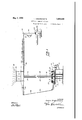
- Fig. 1 is a fragmentary view in elevation of the improved airplane loading station with the supporting balloon broken away and with an airplane contacting with thestation and being supplied with gasoline.
- ig. 2 is a View of the gangplank or arm supported by the balloon with an airplane contacting therewith in position to take on passengers or freight.
- Fig. 3 is a plan View of the same.
- Fig. 4 is a plan view of the gangplank with an airplane contacting therewith showing its circling movement.
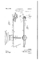
- Fig. 5 is a plan view of the turntable platform upon which the anchoring cable winches are carried.
- Fig. 6 is a view of the same partly in elevation and partly in medial vertical section.
- my improved invention comprises a structural framework 1 which supports in a horizontal plane a circular trackway 2.
- the trackway 2 is in the form of a channel iron arranged with the web 3 in a vertical plane and with the flanges 4 and 5 facing inwardly toward the center of the trackway.
- a turntable platform 6 is rotatably mounted on the trackway 2 by having a plurality of depending brackets 7 on the under side upon which are journalled rollers or wheels 8.
- the rollers 8 extend into the loosely fit between the upper and lower flanges 4 and 5 of the channel trackway 2.
- the under side of the latform 6 around its marginal edge is provided with a circular toothed ring gear 9 which meshes with a pinion gear 10 on the shaft of an electric motor ll.
- the motor 11 is secured to a. supporting bracket arm 12 which is rigidly mounted on. the framework 1.
- the shaft of the motor 11 is also provided with a brake and brake drum 13 for the purpose of retard ing rotation of the platform, the brake band of which is contracted by a brake lever or ha dle 14.
- the center of the platform 6 is provided
- the platform .6'j also supports a horizon tally disposed multiple drum winch which comprises upstanding bearing brackets 19, and 21 bolted to the platform at then lower ends and having. aligned boxings 1n the1r upper ends in which is journalled a line shaft 22.
- the line shaft22 hasrigidly mounted thereon cable drums 23, 24 and 25 which receive and are adapted to have wound thereon suitable cables 26, 27 and 28 respectively.
- the winch line shaft 2 2 has a worm gear 29 keyed thereto which is driven bya worm 30 onthe armature shaft of an electric motor 31 which is also mountedOnth platform 6.
- the cables 26, 27 and 28 are attached to and anchor to the platform a substantially horizontally disposed'gangplank or arm 36 which is supported and normally held in spaced relation to the earth by a balloon 37 whose netwark 38 is attached to a ring39.
- the ring 39 is in turn secured by a standard 40 to the gangplank 36.
- 7 i i The gangplank 36 is supported by the balloon closely adjacent one end thereof and the anchoring cables 27 and '28 are attached thereto directly under the" point of attachment of the balloon '37.
- the short end 41 of the gang-plank has the anchor cable 26 attached tothe outer end thereof for'counterbalancing the longer end of said gangplank which extends outwardly a considerable distance; I
- the gasoline hose 18 extends upwardly along the cables 27 and 28 and then-outwardly on the gangplank36 to the outer'free end 42" thereof thencedownwardly through an opening in the 'gangplank so that gasoline maybe supplied to an airplane 43which is attached'to the end 42 of the gangplank by a cable 44.
- the outer end42' of the gangplank 36 is also provided with a stairway hinged thereto at one end which may be lowered as shown in Fig. 2 ofthe drawings so that passengers or freight and express matter may be loaded into the'airplane 43 when drawn 'gangplank 36 in substantially horizontal position several hundred feet in the ,air, the cables 26, 27 and 28 anchoring the balloon and gangplank to the rotatable platform 6.
- the en'ti'relanding station may be quickly brought to a standstill by application of the brake 13 and the balloon and gangplank supported thereby maybe quickly drawn down close to the platform 6 by operation of the winch mounted on said platform.
- An'airplane loading station comprising a substantially horizontally disposed arm having'one end adapted to be connected'to an airplane, a balloon attached to said arm for supporting it in the air, flexible. cables for anchoring said arm and balloon to the earth, and means for rotating the horizontal arm at substantially airplane speed, the flexible cables permitting lateral swaying of the arm to I yield to airplane pull.
- An airplane loading station comprising a turntable platform, a balloon, flexible cables anchoring said balloon to said platform, an arm supported by said balloon having one end thereof adapted to be connected to an airplane, and means for rotating the said arm .at substantially airplane speed.
- An airplane loading station comprising a turntable platform, a balloon, a winch mounted on said platform, cables on said winch connected to said balloon, an arm supported by said balloon having one end thereof adapted to be connected to an airplane, and means for rotating the said arm at substantially airplane speed, the said cables permitting lateral swing of the arm to permit the same to yield to airplane pull.
- An airplane loading station comprising a turntable platform, means for rotating said platform, a multiple drum winch on said platform, a balloon, cables connecting said winch drums with said balloon, an arm supported by said balloon having one end thereof adapted to be connected to an airplane, and means for rotating the said arm at substantially airplane speed, the said cables permitting lateral swaying of the arm to enable the same to yield to airplane pull.
- An airplane loading station comprising a turntable platform, means for rotating said platform, a brake'for retarding the rotation of said platform, a multiple drum winch on said platform, a balloon, cables connecting said winch drums with said balloon, an arm 40 supported by said balloon having one end thereof adapted to be connected to an airplane, and means for rotating the said arm substantially at airplane speed, the said cables permitting lateral swaying of the said arm to yield to airplane pull.
- An airplane loading station comprising a balloon, a gangplank supported by said balloon, means for anchoring said balloon to the earth, and a stairway section pivoted on said so gangplank adjacent the outer end of the lat ter and located beneath and extending downwardly and outwardly from the said gangplank.
Landscapes
- Engineering & Computer Science (AREA)
- Mechanical Engineering (AREA)
- Aviation & Aerospace Engineering (AREA)
- Toys (AREA)
Description
May a, 1932.
L. VINGHEROETS 1,856,446
AIRPLANE LOADING STATION Filed March 8, 1929 4 Sheets-Sheet l INVENTOR. Zauzs l/mgh eroets A TTORNEYS y 1932- 1.. VINGHEROETS 1,856,446
AIRPLANE LOADING STATION Filed March 8, 1929 4 Sheets-Sheet 2 INVENTOR. Louzs l/zngn eroeis 287551041111. ayfifigw ATTORNEYS May 3, 1932.
L. VINGHEROETS AIRPLANE LOADING STATION Filed March 8, 1929 4 Sheets-Sheet 3 INVENTOR. Zouis Z/z'ng/z ero e25 ATTORNEYS y 1932- L. VINGHEROETS 1,856,446
AIRPLANE LOADI NG STATION Filed March 8, 1929 4 Sheets-Sheet 4 INVENTOR. Zouz's Vingh era e25 A TTORNEYS Patented May 3, 1932 PATENT OFFICE LOUIS VINGHEROETS; F GRAND RAPIDS, MICHIGAN AIRPLANE LOADING STATION,
Application filed March 8, 1929. Serial No. 345,427.
This invention relates to an airplane loading station.
The main objects of this invention are to provide an improved loading station for airplanes whereby the planes can refuel and take on passengers, mail and freight while in mid-air without necessitating the landing of the plane; to provide a loading station which is freely suspended in the air by means of a balloonas distinguished from structures supported on rigid towers and the like; and to provide a loading station which is adapted to beibuilt upon the ground or carried upon a motor truck or upon a boat.
An illustrative embodiment of this invention is shown in the accompanying drawings, in which:
Fig. 1 is a fragmentary view in elevation of the improved airplane loading station with the supporting balloon broken away and with an airplane contacting with thestation and being supplied with gasoline.
ig. 2 is a View of the gangplank or arm supported by the balloon with an airplane contacting therewith in position to take on passengers or freight.
Fig. 3 is a plan View of the same.
Fig. 4 is a plan view of the gangplank with an airplane contacting therewith showing its circling movement.
Fig. 5 is a plan view of the turntable platform upon which the anchoring cable winches are carried.
Fig. 6 is a view of the same partly in elevation and partly in medial vertical section.
Heretofore many devices have been proposed having for their objects the landing of airplanes on the tops of buildings and the like, the purpose being to permit airplanes to land and. take off from the downtown districts of large cities. At the present time the mail planes and the like necessarily have to come in at the landing fields which are generally located many miles-from the middle l I ofany large metropolis and much time is conwere possible for airplanes to make contact in the heart of business districts for the purpose of taking on or unloading passengers, mail and the like.
By use of the present invention, it is possible for airplanes to fly directly to the heart of business districts and there make contact with my improved loading station which loading station may be mounted on the top of any building without regard to its having a large roof area. Furthermore, loading stations of my improved design may be mounted upon motor trucks and thereby rendered mobile for use in warfare, also on boats and ships in mid-oceam'anchored or otherwise. Every ship afloat atthe present time could be equipped with a loading station of this character and airplanes making transoceanic flights could thereby follow the usual shipping lanes and refuel by giving appropriate signals to whatever ship they might sight without landing of the plane on the said ship.
In the construction shown in the drawings, my improved invention comprises a structural framework 1 which supports in a horizontal plane a circular trackway 2. The trackway 2 is in the form of a channel iron arranged with the web 3 in a vertical plane and with the flanges 4 and 5 facing inwardly toward the center of the trackway. A turntable platform 6 is rotatably mounted on the trackway 2 by having a plurality of depending brackets 7 on the under side upon which are journalled rollers or wheels 8. The rollers 8 extend into the loosely fit between the upper and lower flanges 4 and 5 of the channel trackway 2.
The under side of the latform 6 around its marginal edge is provided with a circular toothed ring gear 9 which meshes with a pinion gear 10 on the shaft of an electric motor ll. The motor 11 is secured to a. supporting bracket arm 12 which is rigidly mounted on. the framework 1. The shaft of the motor 11 is also provided with a brake and brake drum 13 for the purpose of retard ing rotation of the platform, the brake band of which is contracted by a brake lever or ha dle 14. L
The center of the platform 6 is provided The platform .6'j also supports a horizon tally disposed multiple drum winch which comprises upstanding bearing brackets 19, and 21 bolted to the platform at then lower ends and having. aligned boxings 1n the1r upper ends in which is journalled a line shaft 22. The line shaft22 hasrigidly mounted thereon cable drums 23, 24 and 25 which receive and are adapted to have wound thereon suitable cables 26, 27 and 28 respectively. The winch line shaft 2 2 has a worm gear 29 keyed thereto which is driven bya worm 30 onthe armature shaft of an electric motor 31 which is also mountedOnth platform 6. IfThe-shaft supporting bracket 19-1s providedwitha horizontally disposed radially extending arm 32, the outer endof which has a cable shive 33 journalled therein around which the cable 26 passes and a second cable shive 34, mounted 'on' an upstanding bracket 35, ismounted on the platform near the middle and to one'side of the cable drum 23 for guiding the cable 26 on to said drum.
' The cables 26, 27 and 28 are attached to and anchor to the platform a substantially horizontally disposed'gangplank or arm 36 which is supported and normally held in spaced relation to the earth by a balloon 37 whose netwark 38 is attached to a ring39. The ring 39 is in turn secured by a standard 40 to the gangplank 36. 7 i i The gangplank 36 is supported by the balloon closely adjacent one end thereof and the anchoring cables 27 and '28 are attached thereto directly under the" point of attachment of the balloon '37. The short end 41 of the gang-plank has the anchor cable 26 attached tothe outer end thereof for'counterbalancing the longer end of said gangplank which extends outwardly a considerable distance; I
The gasoline hose 18 extends upwardly along the cables 27 and 28 and then-outwardly on the gangplank36 to the outer'free end 42" thereof thencedownwardly through an opening in the 'gangplank so that gasoline maybe supplied to an airplane 43which is attached'to the end 42 of the gangplank by a cable 44.
The outer end42' of the gangplank 36 is also provided with a stairway hinged thereto at one end which may be lowered as shown in Fig. 2 ofthe drawings so that passengers or freight and express matter may be loaded into the'airplane 43 when drawn 'gangplank 36 in substantially horizontal position several hundred feet in the ,air, the cables 26, 27 and 28 anchoring the balloon and gangplank to the rotatable platform 6.
When it is desired to have an airplane make contact with the loading station, electric 'm'otor'll' is operated so as to turn the platform 6 and thereby rotate the gangplank 36 andballoon 37 mainly through the pull of thecable 26 which is attached to the outer end 41 of the gangplank. When the gangplank has attained a speedof somewhat the same as the flying speed of the airplane, the cable 44 attached to the outer swinging end 42 of the'gangplank is picked up by the airplane and attachment made thereto.
"If only gasoline is to be loaded,ithe plane continues itsflight in a circle somewhat as showniin Fig. 4 of the drawings, it being readily apparentthat slight variations in the course of the plane are compensated for by the flexible cable 44 which attachesit to the platform and also by reason of the fact that the ballon and gangplank are freely floating about in the air and may sway off to one side oranotlier depending upon the pull ofthe airplane. The hose 18 is passedto the gasoline tank of the airplane and opened and thereby'a supply of gasoline taken aboard.
If passengers or freight or'mail matter is to be loaded on the airplane, after it has made contact with the loading station'and become attached to the cable 44 itis drawn up into close proximity to the outer end 42 of the gangplank at which time the stairway 45 is lowered as shown in Fig.2 of the drawings I and mail matter, freight and express matter or even passengers loaded into the plane while it continues it flight round and round.
After the plane takes on fuel or is loaded and disconnects from the outer'end of the gangplank, the en'ti'relanding station may be quickly brought to a standstill by application of the brake 13 and the balloon and gangplank supported thereby maybe quickly drawn down close to the platform 6 by operation of the winch mounted on said platform. V Although'bu't' one specific embodiment of this invention has been herein shown and described, it will be understood that nu'mer- 1 ous details of the construction shown may.
bealtered or omitted without departing from v the spirit of this invention as defined by the following claims.
Iclaimz' a 1. An'airplane loading station comprising a substantially horizontally disposed arm having'one end adapted to be connected'to an airplane, a balloon attached to said arm for supporting it in the air, flexible. cables for anchoring said arm and balloon to the earth, and means for rotating the horizontal arm at substantially airplane speed, the flexible cables permitting lateral swaying of the arm to I yield to airplane pull.
2. An airplane loading station comprising a turntable platform, a balloon, flexible cables anchoring said balloon to said platform, an arm supported by said balloon having one end thereof adapted to be connected to an airplane, and means for rotating the said arm .at substantially airplane speed.
3. An airplane loading station comprising a turntable platform, a balloon, a winch mounted on said platform, cables on said winch connected to said balloon, an arm supported by said balloon having one end thereof adapted to be connected to an airplane, and means for rotating the said arm at substantially airplane speed, the said cables permitting lateral swing of the arm to permit the same to yield to airplane pull.
4. An airplane loading station comprising a turntable platform, means for rotating said platform, a multiple drum winch on said platform, a balloon, cables connecting said winch drums with said balloon, an arm supported by said balloon having one end thereof adapted to be connected to an airplane, and means for rotating the said arm at substantially airplane speed, the said cables permitting lateral swaying of the arm to enable the same to yield to airplane pull.
5. An airplane loading station comprising a turntable platform, means for rotating said platform, a brake'for retarding the rotation of said platform, a multiple drum winch on said platform, a balloon, cables connecting said winch drums with said balloon, an arm 40 supported by said balloon having one end thereof adapted to be connected to an airplane, and means for rotating the said arm substantially at airplane speed, the said cables permitting lateral swaying of the said arm to yield to airplane pull.
- 6. An airplane loading station comprising a balloon, a gangplank supported by said balloon, means for anchoring said balloon to the earth, and a stairway section pivoted on said so gangplank adjacent the outer end of the lat ter and located beneath and extending downwardly and outwardly from the said gangplank.
In testimony whereof I have hereunto set my hand at Grand Rapids, Michigan, this 5th day'of March, 1929.
LOUIS VINGHEROETS.
Priority Applications (1)
| Application Number | Priority Date | Filing Date | Title |
|---|---|---|---|
| US345427A US1856446A (en) | 1929-03-08 | 1929-03-08 | Airplane loading station |
Applications Claiming Priority (1)
| Application Number | Priority Date | Filing Date | Title |
|---|---|---|---|
| US345427A US1856446A (en) | 1929-03-08 | 1929-03-08 | Airplane loading station |
Publications (1)
| Publication Number | Publication Date |
|---|---|
| US1856446A true US1856446A (en) | 1932-05-03 |
Family
ID=23354995
Family Applications (1)
| Application Number | Title | Priority Date | Filing Date |
|---|---|---|---|
| US345427A Expired - Lifetime US1856446A (en) | 1929-03-08 | 1929-03-08 | Airplane loading station |
Country Status (1)
| Country | Link |
|---|---|
| US (1) | US1856446A (en) |
Cited By (3)
| Publication number | Priority date | Publication date | Assignee | Title |
|---|---|---|---|---|
| US4009850A (en) * | 1975-04-21 | 1977-03-01 | Hickey John J | Airship tankers |
| US5497962A (en) * | 1994-10-11 | 1996-03-12 | Lockheed Corporation | Mooring tower assembly for a lighter-than-air vehicle |
| US10730640B2 (en) * | 2018-03-14 | 2020-08-04 | Milivoj Plisic | Launch system apparatus |
-
1929
- 1929-03-08 US US345427A patent/US1856446A/en not_active Expired - Lifetime
Cited By (3)
| Publication number | Priority date | Publication date | Assignee | Title |
|---|---|---|---|---|
| US4009850A (en) * | 1975-04-21 | 1977-03-01 | Hickey John J | Airship tankers |
| US5497962A (en) * | 1994-10-11 | 1996-03-12 | Lockheed Corporation | Mooring tower assembly for a lighter-than-air vehicle |
| US10730640B2 (en) * | 2018-03-14 | 2020-08-04 | Milivoj Plisic | Launch system apparatus |
Similar Documents
| Publication | Publication Date | Title |
|---|---|---|
| US1748663A (en) | Method and means for landing and launching aircraft and aircraft freight | |
| US4402479A (en) | Small tethered aerostat relocatable system | |
| CN105564663A (en) | Airplane suspension type full-automatic take-off and landing system and take-off and landing method | |
| US1770675A (en) | Mooring device | |
| CN106494645A (en) | A kind of fast cable system | |
| US1856446A (en) | Airplane loading station | |
| US1748500A (en) | Mooring of airships | |
| US2312533A (en) | Aerial merry-go-round | |
| US1706065A (en) | Airplane-launching gear | |
| US2704193A (en) | Method and apparatus for mooring airships | |
| CN202414173U (en) | Fixed mooring system for tethered balloon | |
| US1829474A (en) | Method and device for establishing communication between aircraft in full flight and the ground | |
| US1912722A (en) | Aerial aircraft carrier | |
| US1813986A (en) | Take off and landing apparatus for airplanes | |
| KR102015758B1 (en) | Flying object with a multi-purpose landing gear module | |
| US3211429A (en) | Means and method of hoisting cargo | |
| RU2339548C1 (en) | Mobil device for lighter-than-air craft holding | |
| US1546443A (en) | Flying machine | |
| US1867591A (en) | Dirigible air dock | |
| SU14574A1 (en) | Device for take-off of an aircraft, with the use of an aircraft temporarily carrying an aircraft, a mast of suspension and delay cables | |
| US3040674A (en) | Aircraft positioning and locating system | |
| US2048950A (en) | Aircraft lift rotor and rotor pack | |
| US1806939A (en) | Starting and landing device fob airships of the lighter than air type | |
| US1853777A (en) | Method of and apparatus for berthing airships | |
| US1351931A (en) | ullmann |