US1856438A - Haymaker - Google Patents
Haymaker Download PDFInfo
- Publication number
- US1856438A US1856438A US332487A US33248729A US1856438A US 1856438 A US1856438 A US 1856438A US 332487 A US332487 A US 332487A US 33248729 A US33248729 A US 33248729A US 1856438 A US1856438 A US 1856438A
- Authority
- US
- United States
- Prior art keywords
- shaft
- feeder
- lever
- hay
- vehicle
- Prior art date
- Legal status (The legal status is an assumption and is not a legal conclusion. Google has not performed a legal analysis and makes no representation as to the accuracy of the status listed.)
- Expired - Lifetime
Links
Images
Classifications
-
- A—HUMAN NECESSITIES
- A01—AGRICULTURE; FORESTRY; ANIMAL HUSBANDRY; HUNTING; TRAPPING; FISHING
- A01D—HARVESTING; MOWING
- A01D89/00—Pick-ups for loaders, chaff-cutters, balers, field-threshers, or the like, i.e. attachments for picking-up hay or the like field crops
Definitions
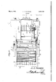
- Figure 1 shows, in top plan, a device constructed in accordance with the invention, parts being broken away;
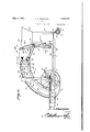
- Figure 2 is a side elevation
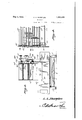
- Figure 3 is a transverse section taken at a point adjacent to the feeder
- Figure 4 is a fragmental transverse section taken approximately on the line 44 of Figure 1;
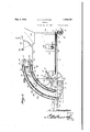
- Figure5- is a longitudinal section of the complete machine
- Figure 6 is a plan showing one of the clutch mechanisms thrown out
- Figure 7 is a view similar to Figure 6, the clutch mechanism being thrown in;
- Figure '8 is a transverse section showing the means whereby the clutch mechanism is operated
- FIG. 9 is a detail PQISPECtlVG view showing the mounting of the clutch lever and attendant parts
- FIG. 10 is a sectional view showing the clutch lever and attendant parts.
- a vehicle including a frame which is denoted generally by the numeral 1.
- Parts of the'frame l which have any important function in the operation of the machine, will be alluded to specifically, as the description of the invention progresses.
- a rear axle 2 On the frame 1 is mounted a rear axle 2, carrying rear ground wheels 3.
- the forward axle is designated by the numeral 4, and is pivotally mounted at 5 on the forward end of the vehicle frame 1, for horizontal swinging movement, in the usual way. Any suitable draft means, such as a tongue 6, is connected to the forward axle 4;.
- Forward ground wheels 7 are journaled on the for- Ward axle 4. I r
- a support 8 in the form of a rod, extends transversely of the vehicle, and passes through inclined lifting blocks 11 on the forward ends of rake tines 9, the points of the rake tines being designated by the numeral 12.
- the support or rod 8 can turn in the lift ing blocks 11.
- the rear ends 10 of the rake tines 9 are upwardly curved, as shown clearly in Figure 5 of the drawings.
- Suspension rods 14 are connected to the ends of the support 8, and slide in guides 15 mounted onthe sides of the frame'l. seg ments 16 are secured to the frame 1.
- Levers 17 are fulcrumed on the segments16 and are pivotally connected, at their rear ends, with the upper ends of the suspension rods 14.
- the levers 17 are supplied with latches 18 adapted to cooperate with the segments 16.
- the forward ends of rigid links 19 are pivotally connected with the rake tines 9, the rear ends of the links being pivotally connected to a cross bar 20 which forms part of the frame 1 of the vehicle.
- the opposite side portions of the frame 1 are connected by an arched standard 21.
- a platform 22 On the forward part of the frame 1 a platform 22 is mounted.
- the platform 22 supports a baling press 23, which may be of any de* sired construction.
- the baling press 23 includes a hopper 24:.
- the bales of hay may be discharged at the side of the vehicle, in the direction of the arrow A in .
- Figure 1 The device includes a horizontal feeder 25, discharging into the hopper 24 of the press 23.
- fourth track 30 is disposed parallel to the third track 29 and is mounted on the feeder 25,.on the standard 21, and on the rear. part of the frame 1.
- a first shaft 31 is journal ed in the frame 7 lat the rear end thereof, as shown in Figure 5.
- a second shaft 32 isjournaled in the rear part of the frame 1 and-is located slightlyin advance of the shaft 31.
- a third shaft 33 is journaled in the upper part of the feeder 25.
- a fourth shaft v34 is journaled in the feederg25 and is located below the shaft 133.
- Sprocket wheels :35 are mounted on the shafts 31 and 33.
- a top conveyor 36 is provided, and includes slats 37 connected by chains 38.
- Thechains 38 engage-the sprocket wheels 35 on the shafts 31 and 33.
- the upper runs. of the chains 38 move along the second track-27, and the lower. runs of the said chains move along the track 26.
- the guides 44 are supplied with outwardly-extended arms'45( Figure1) which are connected to any accessible partof the machine, for instance,"to the feeder 25.
- the guides -44 converge as they extend upwardly and'forwardly.
- the rolls 46- arezcarried, respectively, by an upper shaft 47 and a-lower shaft 48,these shafts beingj ournaledin the feeder 25.
- a shaft .96 is supportedjforrQtationon.a
- the sprocket wheel 98b is supported at 980 for rotation on the feeder 25.
- a gear wheel 98d turns withthe sp-rocket'wheel 985.
- a gear wheel98e meshes with the gear wheel 98d, and is secured to the shaft 53 which carries the hay stops 55.
- the sleeve 61 is provided with a'circumferential camtrack 64, in which is received slidably the extremity of the ,curved end 66 ,of a lever 65, the lever being fulcrumed at 67 on a bracket 68 which is mounted on the hanger 99. f
- a 'link 7 9 ( Figure3) connects the lever 65 with amovable part of the baling .press,.so that at a proper step in the operation of the baling press, motion will be transmitted to the lever 65, thereby to slide the sleeve 61 longitudinally and shift.- the clutch; elements 63 :of itlle sleeve Gland- :of-itheitubnlar shaft 57 into and out ofv engagement with each other.
- a retractile spring 69 is connected to the lever 65 and is anchored on the hanger 99 or elsewhere, the function of the spring 69 being to swing the curved end 66 offthe lever 65 to the right in Figure 6, so that the tubular shaft 57 is not coupled to the shaft 96 by the clutch elements 63.
- the lever 65 is provided with a projection 74.
- a latch 7 is fulcrumed at 71 on the bracket 68, the latch having a cam edge 72 which lies in the path of a radial finger 73 on the shaft 96, the latch 70 being held by a retractile spring 75 in such a position that the cam edge 72 is in the path of the finger '7 3 on the shaft 96.
- a stop 76 is pivoted at 77 to the lever 65 and slides-in a guide 78 which is mounted on the bracket 68 Let it be supposed that the stops 55 on the shaft 53 are extended into the feeder 25, as
- the curved end 66 of the lever 65 has been swung to the right, as iii- Figure 6, and the clutch elements 63 ofthe sleeve 61 and of the shaft 57 are out of engagement with each other, the shaft 96 being at rest, and the shaft 57 being free to turn.
- the projection 74 on the lever 65 is between the latch 7 0 and the edge of the bracket 68, and the stop 76 is advanced so that it extends into the path of the finger 73 on the shaft 53, thereby to hold the shaft 96 against turning, the hay stops on the shaft 53 being held ⁇ fixed into the feeder 25, as disclosed in Figures 5 and 1.
- the engine 59 operates the baling press 23 through the instrumentality of the mechanism shown at 60.
- the engine59 drives the chain and sprocket connection 58, and the tubular shaft 57 is rotated on the shaft 96.
- the shaft 96 and the shaft 53 do not rotate, and the stops 55 remain in a fixed position in the feeder 25 because the clutch elements 63 are out of engagement.
- the hay is gathered by the tines 9 and is lifted by the blocks 11 over the rod 8.
- the hay moves backwardly and upwardly upon the rear ends 10 of the tines 9, and by the time that the hay is on the curved ends 10 of the tines 9, the hay is caught by the inner hay reaches the feeder 25, the hay is in a a mass that is narrow enough to pass readily into thefeeder.
- the rolls 46 compress the hay and force it forwardly in the feeder 25, against the stops 55, the stops being called by that name because they stop the forward movement of the hay in the feeder 25.
- the shaft 96 makes a complete rotation, to restore the hay stops 55 to position of Figure 5, and in this rotation, the finger 73 on the shaft 96 wipes along the cam edge 72 of the latch 70, and the latch is tilted on its fulcrum 71, the end 81 of the latch being disengaged from the projection 74, so that the lever 65, under the action of the spring 69, and under the action of the part ( Figure 3) of the baling press 23, can move from the position of Figure 7 to the position of Figure 6, the clutch elements 63 being disengaged, the projection 74 on the lever 65 passing beneath the arm of the latch 70, and the stop 76 be- V 55' in the position shown in I Figure :5.
- the machine hereinbe fore described straddles a windrowoi hay, gathers-it up, andbales it on the-gob "Wha t is claimedis l.fI-n af'dev-ice of the-class descri'bed, a vehicle, a feeder thereon, a'movably mounted stop inthe'ieeder, a conveyor on the vehicle feeder, a rake on the vehicle and extended upwardly and rearwardly .to the lower rear end of the conveyor, a driving device for the conveyor, an engine on the vehlcleand opera- I tively connected to the driving'idev-ice, clutch mechanism for coupling the stop'to the driving device, and means for operating the clutch mechanism automatically at intervals from the driving-device', through power de .rivedi-rom .the' engine and independently of an operator to withdraw the stop from the feeder and then return therstop into the feeder.
- a ve masses advance of .thexiconveyors, the guides constituting means for compacting the material for delivery into the feeder as;the material is advancedlbythe conveyors, .a rake on the vehicle and delivering the material between the" conveyors, and automatically acting means for movingthe stop out of the feeder at intervals;
- a vehicle ground wheels mounted 'to'rotate on the vehicle on a horizontal axis, a conveyor on :the vehicle, and extendedupwardly and torwardly,.means forreceiving material from the upper forward end of the conveyor, a rake on the vehicle and extended; upwardly and rearwardly to the lower rear end of the conveyor, the vforward end :of therake being locatedi-in the same vertical plane with-the horizontal axis on "whichthe ground wheels are mountedto rotate, and means for raising and lowering the iorwarden'd oi the rake at thewi'lLo f an operator.
- a vehicle ground-wheels mounted to rotate on thevehicle on a horizontal axis, spacedconveyors-on the vehicle and extended upwardly and forwardly, lneansfor receiving material from the upper forward endsvoi the conveyors, guides supported between the conveyors rake on the vehicle, the rear end of the rake *being soplaced as to deliver the material between the conveyors, the forward end of the rakebeinglocated in theisa'me vertical plane with the horizontal axis 'on which the ground wheels rotate.
- a vehicle spaced conveyors onvthe vehicle, the upper forward ends of the conveyors being locatedin a substantially horizontalposibeing located in .a substantially vertical position, a "rake having annpwardly curved rear end located closely adjacent to the forward sideotthe'lowerrear end of the rearmost conveyor, mea'ns'forsupporting the rear por- 1.
- a. feeder thereon, a movably mounted v I stop in the feeder, spaced conveyors on the vehicle and extended upwardly and forwardly to the feeder, guides supported between the conveyors andconverging the direction of tion,and the lower rear ends of the conveyors 1.
Description
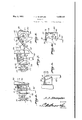
May 3, 1932. A. A. SHARPLES HAYMAKER 5 Sheets-Sheet l .Fileci Jan. 14, 1929 A d Shi ales I I l I I I I I I I l May 3, 1932. A. A; SHARPLES HAYMAKER Filed Jan. 14, 1929 5 Sheets-Sheet 4 May 3, 1932. A. A. SHARPLES HAYMAKER Filed Jan. 14, 1929 5 Sheets-Sheet 5 Patented May 3, 1932 PATENT oFTIcE ARTHUR A. SHARPLES, 0F STOCKDALE, KANSAS HAYMAKER Application filed January 14, 1929. Serial No. 332,487.
This invention has as one of its obj ects, the provision of novel means whereby hay may be raked and then conveyed to a feeder which discharges into a baling press. Another object of the invention is to provide novel ms ans whereby the hay will be delivered into the feeder at a proper step in the operation of the press. A further object of the invention is to provide a novel mechanism whereby the hay is raked.
It is within the province of the disclosure to improve generally and to enhance the utility of devices of that type to which the invention appertains.
\Vith the above and other objects in view, which will appear as the description proceeds,the invention resides in the combination and arrangement ofparts and in the details of construction hereinafter described and claimed, it being understood that changes in the precise embodiment of the invention herein disclosed, may be made within the scope ofwhat is claimed, without departing from the spirit of the invention.
In the accompanying drawings Figure 1 shows, in top plan, a device constructed in accordance with the invention, parts being broken away;
Figure 2 is a side elevation;
Figure 3 is a transverse section taken at a point adjacent to the feeder;
Figure 4 is a fragmental transverse section taken approximately on the line 44 of Figure 1; I
Figure5- is a longitudinal section of the complete machine;
Figure 6 is a plan showing one of the clutch mechanisms thrown out;
Figure 7 is a view similar to Figure 6, the clutch mechanism being thrown in;
Figure '8 is a transverse section showing the means whereby the clutch mechanism is operated;
Figure 9 is a detail PQISPECtlVG view showing the mounting of the clutch lever and attendant parts;
' Figure 10 is a sectional view showing the clutch lever and attendant parts.
In carrying out the invention, there is provided a vehicle including a frame which is denoted generally by the numeral 1. Parts of the'frame l which have any important function in the operation of the machine, will be alluded to specifically, as the description of the invention progresses.
On the frame 1 is mounted a rear axle 2, carrying rear ground wheels 3. The forward axle is designated by the numeral 4, and is pivotally mounted at 5 on the forward end of the vehicle frame 1, for horizontal swinging movement, in the usual way. Any suitable draft means, such as a tongue 6, is connected to the forward axle 4;. Forward ground wheels 7 are journaled on the for- Ward axle 4. I r
A support 8, in the form of a rod, extends transversely of the vehicle, and passes through inclined lifting blocks 11 on the forward ends of rake tines 9, the points of the rake tines being designated by the numeral 12. The support or rod 8 can turn in the lift ing blocks 11. The rear ends 10 of the rake tines 9 are upwardly curved, as shown clearly in Figure 5 of the drawings.
Suspension rods 14: are connected to the ends of the support 8, and slide in guides 15 mounted onthe sides of the frame'l. seg ments 16 are secured to the frame 1. Levers 17 are fulcrumed on the segments16 and are pivotally connected, at their rear ends, with the upper ends of the suspension rods 14. The levers 17 are supplied with latches 18 adapted to cooperate with the segments 16. The forward ends of rigid links 19 are pivotally connected with the rake tines 9, the rear ends of the links being pivotally connected to a cross bar 20 which forms part of the frame 1 of the vehicle.
The opposite side portions of the frame 1 are connected by an arched standard 21. On the forward part of the frame 1 a platform 22 is mounted. The platform 22 supports a baling press 23, which may be of any de* sired construction. As disclosed, but not necessarily, the baling press 23 includes a hopper 24:. The bales of hay may be discharged at the side of the vehicle, in the direction of the arrow A in .Figure 1. The device includes a horizontal feeder 25, discharging into the hopper 24 of the press 23.
Referring to Figure 5, in connection with Figure 4, it will be observed that a curved of the frame 1.' Disposed abovethe first track .26, in parallel relation thereto, is a curved second track '27 which is connected to the first track 26 by brackets 28. A third track 29, which may be an angle member, is
disposed parallel to the tracks 26 and'27,
and is secured to the feeder 25, the standard 21 and the rear part of the frame 1;A.
27, shown in section in Figure 4at one side of the -machine,;are duplicated at the opposite side of the-machine.
. A first shaft 31 is journal ed in the frame 7 lat the rear end thereof, as shown in Figure 5. A second shaft 32 isjournaled in the rear part of the frame 1 and-is located slightlyin advance of the shaft 31. A third shaft 33 is journaled in the upper part of the feeder 25. A fourth shaft v34 is journaled in the feederg25 and is located below the shaft 133.
Sprocket wheels :35 are mounted on the shafts 31 and 33. A top conveyor 36 is provided, and includes slats 37 connected by chains 38. Thechains 38 engage-the sprocket wheels 35 on the shafts 31 and 33. The upper runs. of the chains 38 move along the second track-27, and the lower. runs of the said chains move along the track 26.
provided, and includes chains 41 connected by'slats 42, the slats carryinga flexible body 43 ;preferably;-made of canvas. The'chains 41;are engaged with the sprocket wheels 39. The upper .runs of the chains 41 move-along the tracks 2-9,andthe lower runs of the said chains move along the tracks 30. The upwardly curved rearends 1O of'the rake tines 9 cooperate with the lower rear end of the top conveyor 36, as di'sclosed in Figure 5 of the-drawings. V I I iIn ithespace' between the lower run of the top :conveyor36 and the upper run of the bottom conveyor are located guides 44. At their rear lower ends, the guides 44 are connected to the sides ofthe frame 1. At their upper endsythe guides 44 are supplied with outwardly-extended arms'45(Figure1) which are connected to any accessible partof the machine, for instance,"to the feeder 25. The guides -44converge as they extend upwardly and'forwardly. Compression and feed rolls 46ers located in the feeder 25, one above the other,'the upper-mo'stroll being located in I advance of the shaft 33, .and the lower-most rol l'f'beinglocated in advance of the shaft 34.
The rolls 46-=arezcarried, respectively, by an upper shaft 47 and a-lower shaft 48,these shafts beingj ournaledin the feeder 25. There are pulleys 49 (Figure 3) on the shafts 47 and 48, and the-pulleys are connected by a crossed belt 50 indicated diagrammatically in Figure 2 of the drawings.
In Figure 2 it is shown that-the shafts 47 and 33 are yoked together operatively by a chain and sprocket connection 51, and the shafts 34 and 48 are connected in a like manner asdisclosed at 52. "On the front portion of the feeder 25 there is journaled a horizontal shaft 53, and this shaft carries angular hay stops (Figure .5) that extend backwardly into the feeder 25.
A shaft .96 is supportedjforrQtationon.a
t appears from Figures .6 and 7, that a clutch sleeve6l isymo-untedon theshaft 96 by means of a :pin and slot connection 62, or its equivalent, the construction being such that thersleeve 61 will. rotate with the sleeve 96, although vthe sleeve 61 can be moved lengthwise onthe shafta96. There'is a sprock etwheel 98 on the sleeveGl. A sprocket chain 98a is engaged around the sprocket wheel 98. The sprocket chain 98a engages a sprocket Wheel 98b. The sprocket wheel 98b is supported at 980 for rotation on the feeder 25. A gear wheel 98d turns withthe sp-rocket'wheel 985. A gear wheel98e. meshes with the gear wheel 98d, and is secured to the shaft 53 which carries the hay stops 55. There are clutch elements63 onthe'sleeve 61 and on the tubular shaft 57 the aforesaid clutch elements being moved into and. out of-engagement with each other when the sleeve "61 is moved longitudinally. V
As to the means whereby the sleeve 61 is moved longitudinally, as and for-the purpose specified, it may be stated that the sleeve 61 is provided with a'circumferential camtrack 64, in which is received slidably the extremity of the ,curved end 66 ,of a lever 65, the lever being fulcrumed at 67 on a bracket 68 which is mounted on the hanger 99. f
A 'link 7 9 (Figure3) connects the lever 65 with amovable part of the baling .press,.so that at a proper step in the operation of the baling press, motion will be transmitted to the lever 65, thereby to slide the sleeve 61 longitudinally and shift.- the clutch; elements 63 :of itlle sleeve Gland- :of-itheitubnlar shaft 57 into and out ofv engagement with each other.
A retractile spring 69 is connected to the lever 65 and is anchored on the hanger 99 or elsewhere, the function of the spring 69 being to swing the curved end 66 offthe lever 65 to the right in Figure 6, so that the tubular shaft 57 is not coupled to the shaft 96 by the clutch elements 63. The lever 65 is provided with a projection 74.
i A latch 7 is fulcrumed at 71 on the bracket 68, the latch having a cam edge 72 which lies in the path of a radial finger 73 on the shaft 96, the latch 70 being held by a retractile spring 75 in such a position that the cam edge 72 is in the path of the finger '7 3 on the shaft 96. A stop 76 is pivoted at 77 to the lever 65 and slides-in a guide 78 which is mounted on the bracket 68 Let it be supposed that the stops 55 on the shaft 53 are extended into the feeder 25, as
' shown in Figures 5 and 1 of the drawings.
The curved end 66 of the lever 65 has been swung to the right, as iii-Figure 6, and the clutch elements 63 ofthe sleeve 61 and of the shaft 57 are out of engagement with each other, the shaft 96 being at rest, and the shaft 57 being free to turn. The projection 74 on the lever 65 is between the latch 7 0 and the edge of the bracket 68, and the stop 76 is advanced so that it extends into the path of the finger 73 on the shaft 53, thereby to hold the shaft 96 against turning, the hay stops on the shaft 53 being held\fixed into the feeder 25, as disclosed in Figures 5 and 1.
The engine 59 operates the baling press 23 through the instrumentality of the mechanism shown at 60. The engine59 drives the chain and sprocket connection 58, and the tubular shaft 57 is rotated on the shaft 96. The shaft 96 and the shaft 53 do not rotate, and the stops 55 remain in a fixed position in the feeder 25 because the clutch elements 63 are out of engagement.
When the sleeve 57 is rotated, the chain and sprocket connection 54 rotates the shaft 48, and from the shaft 48, rotation is imparted to the shaft 47 (Figure 2) by the crossed belt 50. Thus, the feed and compression rolls 46 of Figure 5 are rotated.
From the shaft 47, rotation is imparted to the shaft 33 by the sprocketdrive 51 that is shown in Figure 2: and from the shaft 48 rotation is imparted to the shaft 34 by the sprocket drive 52. The sprocket wheels 39 on the shaft 34 actuate the bottom conveyor 40 (Figure 5') and the sprocket wheels 35 on the shaft 33 operate the top conveyor 36.
The hay is gathered by the tines 9 and is lifted by the blocks 11 over the rod 8. The hay moves backwardly and upwardly upon the rear ends 10 of the tines 9, and by the time that the hay is on the curved ends 10 of the tines 9, the hay is caught by the inner hay reaches the feeder 25, the hay is in a a mass that is narrow enough to pass readily into thefeeder. The rolls 46 compress the hay and force it forwardly in the feeder 25, against the stops 55,, the stops being called by that name because they stop the forward movement of the hay in the feeder 25.
After a suflicient quantity of hay has accumulated in the feeder 25, and at a proper step in the operation of the baling press 23, motion is imparted to the lever (Figure 3) by the link 79, and the movable part 80 of the baling press. The lever 65 now is tilted on its fulcrum 67 (Figure 10) from the position of Figure 6 to the position of Figure 7. This operation brings the clutch elements 63 into engagement, so that when the tubular shaft 57 is rotated by the sprocket drive 58 from the engine 59, as hereinbefore explained, rotation will be imparted to the shaft 96 also, the sprocket drive 98 rotating the shaft 53. )Vhen the lever 65 is swung from the position of Figure 6 to the position of Figure 7, the stop 76 is pulled out of the path of the finger 73 on the shaft 96, so that the shaft 96 can rotate, as aforesaid.
When the lever 65 is tilted from the position of Figure 6 to the position of Figure 7, the projection 74 on the lever 65 moves clear of the end of the latch and engages with the end 81 of the latch 70. This holds the lever 65 in the position of Figure 7, with the clutch elements 63 in engagement, rotation being imparted to the shaft 96 from the shaft 57. The shaft 53 (being coupled to the shaft 96 by the chain drive 98 and the sleeve 61) now makes a rotation, to pull out the stops 55 (Figure 5) from in front of the mass of hay in the feeder 25, so that the mass of hay in the feeder can move forwardly in the feeder and down into the hopper 24 of the baling press 23.
The shaft 96 makes a complete rotation, to restore the hay stops 55 to position of Figure 5, and in this rotation, the finger 73 on the shaft 96 wipes along the cam edge 72 of the latch 70, and the latch is tilted on its fulcrum 71, the end 81 of the latch being disengaged from the projection 74, so that the lever 65, under the action of the spring 69, and under the action of the part (Figure 3) of the baling press 23, can move from the position of Figure 7 to the position of Figure 6, the clutch elements 63 being disengaged, the projection 74 on the lever 65 passing beneath the arm of the latch 70, and the stop 76 be- V 55' in the position shown in I Figure :5.
ing advanced into the path of the "finger '73 on-rthe-shaft 96 .to hold theshaft :96 and the shaft/5'3 against rotation, with the hay stops Because :the lever .65 has been'restored to the positionof Figure '6, the shaft'57 can turn,
to operate the conveyors 40 and 36, without rotating the shait-96and :the shaft :53. :This
:is .so, because the clutch elements 63 ofthe shaft 1 57 and of thesleeve 61 *a re disengaged. hen 'th-e lever 65 is tilted, the cam track '64 onthe sleeve 61, cooperating with the extremity :ot' the lever ":65,- aids in imparting longitudinal movement to the sleeve 61, :as
.thesleeve rotates 'wit'h' the shaft '53. r
the wheels The-'resultis that the rake =tines 9-always make aclean pidk-11p, because the front ends 12 ofthe tines are so located that whenthelower-most parts of the ground wheels 8 godown into a depressiomthe ends 12 of the rake tines go down into the depression also and the hay is not passed over and missed. The links 19 of Figure '5 are rigid and take some of the bac-kward'th'rust from the tines 9. This desirable because the strain is divided fairly between the support V and extended upwardly and forwardly to the orf'rod- 8 and the links 19.
The machine hereinbe fore described straddles a windrowoi hay, gathers-it up, andbales it on the-gob "Wha t is claimedis l.fI-n af'dev-ice of the-class descri'bed, a vehicle, a feeder thereon, a'movably mounted stop inthe'ieeder, a conveyor on the vehicle feeder, a rake on the vehicle and extended upwardly and rearwardly .to the lower rear end of the conveyor, a driving device for the conveyor, an engine on the vehlcleand opera- I tively connected to the driving'idev-ice, clutch mechanism for coupling the stop'to the driving device, and means for operating the clutch mechanism automatically at intervals from the driving-device', through power de .rivedi-rom .the' engine and independently of an operator to withdraw the stop from the feeder and then return therstop into the feeder.
eso
2. In a device of the classdescrifbed, a ve masses advance of .thexiconveyors, the guides constituting means for compacting the material for delivery into the feeder as;the material is advancedlbythe conveyors, .a rake on the vehicle and delivering the material between the" conveyors, and automatically acting means for movingthe stop out of the feeder at intervals;
In a. device of the class described, a vehicle, ground wheels mounted 'to'rotate on the vehicle on a horizontal axis, a conveyor on :the vehicle, and extendedupwardly and torwardly,.means forreceiving material from the upper forward end of the conveyor, a rake on the vehicle and extended; upwardly and rearwardly to the lower rear end of the conveyor, the vforward end :of therake being locatedi-in the same vertical plane with-the horizontal axis on "whichthe ground wheels are mountedto rotate, and means for raising and lowering the iorwarden'd oi the rake at thewi'lLo f an operator. g.
4. In a device ofthe class described, a vehicle, ground-wheels mounted to rotate on thevehicle on a horizontal axis, spacedconveyors-on the vehicle and extended upwardly and forwardly, lneansfor receiving material from the upper forward endsvoi the conveyors, guides supported between the conveyors rake on the vehicle, the rear end of the rake *being soplaced as to deliver the material between the conveyors, the forward end of the rakebeinglocated in theisa'me vertical plane with the horizontal axis 'on which the ground wheels rotate. v V
5. In a device ofthe class described, a vehicle, spaced conveyors onvthe vehicle, the upper forward ends of the conveyors being locatedin a substantially horizontalposibeing located in .a substantially vertical position, a "rake having annpwardly curved rear end located closely adjacent to the forward sideotthe'lowerrear end of the rearmost conveyor, mea'ns'forsupporting the rear por- 1.
hicle, a. feeder thereon, a movably mounted v I stop in the feeder, spaced conveyors on the vehicle and extended upwardly and forwardly to the feeder, guides supported between the conveyors andconverging the direction of tion,and the lower rear ends of the conveyors 1.
Priority Applications (1)
| Application Number | Priority Date | Filing Date | Title |
|---|---|---|---|
| US332487A US1856438A (en) | 1929-01-14 | 1929-01-14 | Haymaker |
Applications Claiming Priority (1)
| Application Number | Priority Date | Filing Date | Title |
|---|---|---|---|
| US332487A US1856438A (en) | 1929-01-14 | 1929-01-14 | Haymaker |
Publications (1)
| Publication Number | Publication Date |
|---|---|
| US1856438A true US1856438A (en) | 1932-05-03 |
Family
ID=23298447
Family Applications (1)
| Application Number | Title | Priority Date | Filing Date |
|---|---|---|---|
| US332487A Expired - Lifetime US1856438A (en) | 1929-01-14 | 1929-01-14 | Haymaker |
Country Status (1)
| Country | Link |
|---|---|
| US (1) | US1856438A (en) |
-
1929
- 1929-01-14 US US332487A patent/US1856438A/en not_active Expired - Lifetime
Similar Documents
| Publication | Publication Date | Title |
|---|---|---|
| US1856438A (en) | Haymaker | |
| US2525870A (en) | Baled hay loader | |
| US2432956A (en) | Beet loader | |
| US2097353A (en) | Cutter attachment for balers | |
| US1233089A (en) | Cranberry-harvesting apparatus. | |
| US2259908A (en) | Pickup baler | |
| US2464684A (en) | Baling press | |
| US1979974A (en) | Harvester pick-up | |
| US2757807A (en) | Bale loader attachment for vehicles | |
| US1508857A (en) | Loader | |
| US1189710A (en) | Feeding mechanism for threshing-machines. | |
| US1834477A (en) | Alfalfa loader | |
| US2050947A (en) | Hay baler | |
| US1790447A (en) | Teanspoetable machine ege scattering geass and hay | |
| US2110501A (en) | Grain shocker | |
| US1102848A (en) | Shock-loader. | |
| US1342217A (en) | Manure-conveyer | |
| US2345542A (en) | Harvesting machine | |
| US1521089A (en) | Sheaf-delivering conveyer for shocking machines | |
| US828552A (en) | Hay-loader. | |
| US1241981A (en) | Hay-baler. | |
| US1552633A (en) | Shocking machine | |
| US1185126A (en) | Automatic shocker. | |
| US982642A (en) | Grain-shocker. | |
| US1092721A (en) | Harvester. |