US1856053A - Knitted fabric and method of making the same - Google Patents
Knitted fabric and method of making the same Download PDFInfo
- Publication number
- US1856053A US1856053A US567555A US56755531A US1856053A US 1856053 A US1856053 A US 1856053A US 567555 A US567555 A US 567555A US 56755531 A US56755531 A US 56755531A US 1856053 A US1856053 A US 1856053A
- Authority
- US
- United States
- Prior art keywords
- loops
- fabric
- course
- courses
- loop
- Prior art date
- Legal status (The legal status is an assumption and is not a legal conclusion. Google has not performed a legal analysis and makes no representation as to the accuracy of the status listed.)
- Expired - Lifetime
Links
Images

Classifications
-
- D—TEXTILES; PAPER
- D04—BRAIDING; LACE-MAKING; KNITTING; TRIMMINGS; NON-WOVEN FABRICS
- D04B—KNITTING
- D04B11/00—Straight-bar knitting machines with fixed needles
- D04B11/06—Straight-bar knitting machines with fixed needles with provision for narrowing or widening to produce fully-fashioned goods
Definitions
- ri ⁇ his invention relates to a novel and improved knitted fabric, more particularly of the full-fashioned type, and to a novel method of making the same, the novel features of which will be best understood from the following description and the annexed drawings, in which li have illustrated selected embodiments ofthe novel fabric and also selected embodiments of a mechanism which may be used in connection with one method of making the fabric.
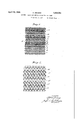
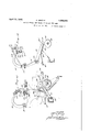
- Fig. 1 is a view on an exaggerated scale showing one form of stitch which may be used in making the fabric.
- Fig. 2 is a View similar to Fig. 1, but showing a different arrangement of stitches which may be employed.
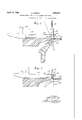
- Figs. 3 to 10, inclusive are diagrammatic views in the form of sections through the sinker head and associated mechanism and showing successive steps in the practicepf'v one method which may be used 1n makingpa' fabric similar to what is shown in Figs. 1y and 2, Figure Z being taken upon a section line through the wale of loops, adjoining the ⁇ vvale through which the preceding Figures B-t are taken.
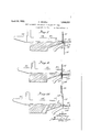
- Figs. 11 and 12 are diagrammatic views' in perspective showing the relation of 'the' different loops of the fabric to each other during the formation of certain stitches.
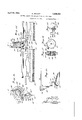
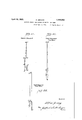
- Fig. 13 is a vertical transverse section through one form of knitting machine illustrating one method of giving one of the necessary movements performed in practicing the invention.
- Fig. 111 is a view similar to Fig. 13, but taken on a different plane parallel to that of Fig. 13 and illustrating one form of mechanism which may be used in giving another movement which cooperates with the movement caused by the mechanism of Fig. 13.
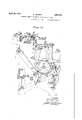
- Fig. 15 is a view on an enlarged scale and taken from the right of Fig. 14, showing the mechanism appearing in the upper part of that ligure.
- Fig. 16 is a view on an enlarged scale taken on the same plane as that of Fig. 14 and showing certain parts appearing in that figure.
- Fig. 17 is a section on the line 17--17 0f Fig. 16.
- Fig. 18 is a section on the line 18-18 of Fig. 15.
- Fig. 19 is a section on the line 19-19 of Fig. 16.
- Fig. 20 is a diagrammatic view showing the control means for some of the mechanism illustrated in the other figures.
- Fig. 21 is a view taken on a plane parallel to the planes of Figs. 13 and 14 and showing the mechanism for operating the needlebar.
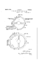
- Fig. 22 is a diagram of the cam.37 drawn on an enlarged scale.
- Fig. 23 is a diagram of one of the cams for causing the needle movement.
- Figs. 24, 25 and 26 are diagrams illustra-ting the movements of the needles and points.
- the fabric constructed according to my invention is one in which it is impossible for a so-called run to take place or in which such a run can be limited, depending upon the specific arrangement of stitches.
- Fig. 1 I have shown therein one form of stitch which will prevent formation of a run in a knitted fabric, particularly of the full-fashioned type, although it is to Vbe understood that the same stitch may be used with other types of knitted fabric.
- the courses designated 1, 2, and 3 are plain courses whichmay be formed in any usual way, and which are shown in this figure by way of contrast with the other courses to be described.
- the loops such as the loop 6, are shown as displaced towards the right, thus changing from one wale to an adjacent Wale, whereas in the course designated 11 similar locking loopsare shown as being displaced to the left, and then in the course designated 12 the locking loops are again shown as being displaced towards the right.
- Intermediate thelocking zones may be one or. more plain courses as desired.
- a short run of one or two courses may not be found undesirable, and therefore the question as to how many courses shall be made with the locking stitches is one largely of choice.
- Fig. 1 I have shown a single plain course 10 and a plain course 13, with the two courses 11 and 14 therebetween.
- Fig. 2 I have shown a similar arrangement in which there are provided plain courses 15 separated by courses 16 and 17, which together form a locking zone, this being very much like the arrangement shown in Fig. 1, except that here the displacement of the locking loops is all in one direction.
- the locking loops are comprising every other loop in a single course, it is possible to use every loop in a course as a locking loop or to have, say, every third or fourth loop as a locking loop.
- the number of loops in a course which are used as locking loops and the number of plain courses between the locking zones may e varied both for economy andv to aid in making different designs of fabric. It will be seen that in no wale is there a continuous line of loops, but that there are loops at appropriate intervals that are offset into adjacent wales and locked there, thus positively preventing a run in the wale from which the loop is oiset.
- Figs. 24, 25 and 26 the various numerals designate points corresponding to Figs. 3 to 10, inclusive, and indicate the positions of the needle and point in each of those figures.
- Fig. 25 shows the position of a certain point cooperating with the needle Whose movement is indicated in Fig. 24, both Figs. 24 and 25 showing the movement of the needle as viewed in the same plane as that in which Figs'. 3 to 10 were taken, whereas Fig-26 shows the movement of a point in a plane at right angles to the aforesaid plane.
- the numeral 4 in Figs. 24, 25 and 26 indicates the position of the needle and point respectively in Fig. 4.
- Figs. 22 and 23 are shown cams which cause the movement of the point and needle according to the diagrams of Figs. 24 and 25.
- Fig. 22 is an enlarged diagram of the cam-37 v appearing in Fig. 13. In Fig. 13 this cam is shown merely in a diagrammatic way without any attempt to indicate its exact form, whereas Fig. 22 is drawn to show more clearly the relations of the various parts of the cam to each other and to the corresponding parts of the cam operating the needle.
- Fig. 23 shows the cam 83 for operating the needle in a vertical plane corresponding to the planes indicatedin Fig. 3. Legends have been placed on Figs. 22 and 23 indicating the portions o f the cam periphery which are in action while the needle and point are in the positions in the various Figures 3 to 10, inclusive. It will not be necessary to repeat the subject matter of these legends herein.
- the successive positions ofthe dierent elements used in fox-min the stitches and the successive positions of t e various threads and the fabric are shown in Fi 3 to 10, inclusive, wherein the numera 18 designates a spring-beard needle adapted to catch a thread and pull it,throfgugh a previously formed loop 1n a manner well known ,in the art.
- the needle shown is one of a row of needles mounted in a needle bar and reciprocated verticall and horizontally by mechanism which is own in the art and which is indicated in Fig. 21.
- Associated with the needle are the usual sinker 19 and a divider 20 which are likewise operated by mechanism known in the art. and shown in Fig. 21.
- Associated with the needles, dividers, and sinkers are grooved lock ⁇ oints, which are shown at 2l in the iigures ein discussed and the operating means lor whic is shown and will be described further in connection with Figs. 13 to 20, inclusive.
- the points are arranged to be recipro-y cated vertically, and horizontally in a plane at right angles to the plane of the drawings, the vertical reciprocation bein on the arc oi a circle, as will be more fu y described later.
- the knitted fabric is leaving the machine in the direction of the arrow and is designated 22.
- the last row of loops 23 is in position on the knocking-over bits 24 and a new course is being formed with the thread 25, at this stage this thread being-termed of sinker loops 26 engaging the sinlrers 19 and needle loops 26 engaging the needles 18.
- the beard 18 of the needle engages the new loop 26 to carry it down through a loop 23, in a manner well known in the art.
- the point 21 is moving downwardly at a faster rate of speed than the needle, and receives the beard 13 in its .groove as shown in Fig. 5, and the lower end 2l' of the point 21 first forces the heard 18 against the shank of the needle and then engages within the loop 23 and pulls it tight as indicated in Fig. 6 and in dotted lines in Fig. l2.
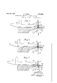
- the needle bar at the same time is moved backwardly or away to the right as appearing in these ligures, and thus4 helps in forming the loop as just described.
- the loop 23 is of a length such that it will extend into the next course oit the fabric. 'lhe needle continues to move downwardly until it leaves the plane of the labric as seen in Fig. 7, still carrying with it the thread forming the new loop, and it will nelly, the Iparts are returned to be seen in'Fig. 7 that the needle is clear of the oint.
- the locking loops 23 are being placed in correct position to perform their loc ing function at the same timethat the next course of loops is being formed from the thread 25. That is to say, a plain course of loops is being formed from the thread 25 simultaneously with the shifting of the locking loops 23.
- Figs. 13 to 20, inclusive I have shown the points 21asmounted on a bar 28, Fig. 15 indicating two such bars disposed adjacent each other for the purpose of knitting separate articles, it being understood that usually a number of articles, such as stockings, are manufactured on'one machine at the same time.
- the bar 28 is fastened to the shaft 29 upon an arm 30, which in turn is secured to a rock shaft 31 mounted in suitable bearings upon the frame of the machine, and this shaft 31 is rocked in order to give the vertical reciprocation of the points 21.
- the reciprocation is caused by a link 32 connected to the shaft 29 and pivoted at 33 to a rocking arm 34 pivoted at one end at 35 to the frame of the machine, and intermedia-te its ends carrying a roller 36 adapted to engage a cam 37 on the wn in.
- the roller engages the cam at its high point 39, which is concentric with the shaft 38 so that passage of the part 39 will not cause actuation of the arm 34.
- Means to be presently described is provided for releasing the arm 34 so that it may be operated by the cam 37.
- a pattern wheel 40 which may be in the form of a wheel rotating on a shaft 41, and having cam faces on opposite sides thereof cooperating with rollers 42 on a guide 43 slidably mounted on the shaft 29.
- the guide 43 is )rovided with ears 44 engaging collars 45 astened on a shaft 46 slidably mounted for longitudinal movement on the frame of the machine.
- brackets 47 Secured rigidly to the shaft 46, as by brackets 47, are the bars 28 in which the points are mounted so that movement of the guide 43 along the shaft 29 causes movement of the points 21 an equal amount.
- the wheel 40 is rotated intermittently as by a pawl and ratchet arrangement, here shown as comprising a ratchet 48 secured to the shaft 41 so as to rotate with the wheel and operated by a pawl 49 pivoted at 50 to an arm 51 of a bell crank lever secured on a rock shaft 52.
- the other arm 53 of the lever has at its end a roller 54 engaging a cam 55 on the cam shaft 38.
- the cam 55 is adapted to intermittently rock the bell crank lever and thus operate the pawl and rotate the ratchet and, consequently, the Wheel 40.
- the pawl is held in yielding engagement with the ratchet as by a spring 56.
- the cams 37 and 55 should be inoperative, and, as pointed out above, the roller ⁇ 36 is held inoperative upon rotation of the cam 37, this being done by a latch 57 engaging a pin 58 on the arm 34.
- the latch 57 is mounted upon a rock shaft 59 upon which is also secured an arm 60 carrying on its end a roller 61 adapted to engage a cam 62 upon the cam shaft 38.
- the roller 61 is, however, slidably mounted upon its shaft 61 which is carried on the end of the arm 60, and, similarly, the roller 54 is slidably mounted on its shaft 54. 1
- These rollers 54 and 61 may be moved on their shafts 54 and 61 to a position Where they do not engage the cams 55 and 62, respectively, and then means is provided for simultaneously moving them into engagement with those cams.
- a forked lever 63 engaging the roller 54 and pivoted on the arm 53 as at 64.
- the roller 61 is engaged by -a forked lever 65 pivoted at 66 on the arm 60.
- a rod 67 Secured to the opposite ends of the levers 63 and 65 is a rod 67 so that movement of this rod 67 will operate both rollers 54 and 61 to bring them into operative relation to the cams 55 and 62, or out of enga ment therewith.
- he rod 67 ma be thus operated by the means shown in ig. 20, which comprises a rock shaft 68 sup orted in suitable brackets 69 on the frame of) the machine and carrying an arm 70 pivoted to the rod 67.
- the other end of the rock shaft may carry an arm 71 pivoted to a. link ,72 which is in turn pivoted to a bell crank lever 73 having at its end a nose 74 disposed in position to be engaged by buttons 75 upon a chain 76 which may be driven by a sprocket 77, which in turn is 0perated by suitable connections from the cam shaft 38.
- the buttons are so arranged that the operation of the rod 67 and, consequently, of the cams 55 and 62, will ca use movement of the points 21 in synchronism with the needle ar to perform the operations de'- scribed above.
- the Wheel 40 forms a pattern wheel which may be varied to obtain any desired arrangement of lock stitches or loops in the knitted fabric, and the buttons 75 on the chain may be varied to control the number of locking zones used in the fabric.
- the arrangement is thus a very flexible one, as the pattern wheel may be changed at will and the buttons 75 may be made replaceable, as well known in the art.
- the chain 76 may be the usual narrowing chain employed in machines of this type, and the buttons 75 are in addition to the buttons normally used in the narrowing operation.
- the wheel 40 may be easily changed by making it of segments as indicated in Fig. 16, and by holding the segments in place as by pins 78 passing through the ratchet 48 on one side.
- I provide on the opposite side of the wheel 40 a second rtachet 79 enga-ging a pawl 80 urged into engagement with the teeth on the ratchet as by a spring 81.
- This is a two-way ratchet used to prevent overrunning and also helps to hold the segments of the Wheel in place.
- a non-run knitted fabric formed of courses and wales of loops, with substantially egaclr Wale containin a multiplicity of loops each of which has a ight portion thereof displaced from an adjacent existent Wale and from an adjacent course, andthe courses wherein such displaced loops occur being in such close meansilnity as to ⁇ render substantially the entire extent of the'fabric of a non-run character, by limiting the breaking effect of any loop of the fabric to a very small number of loops ⁇ in thewale in Whichthe break occurs.
- non-run knitted fabric formed of courses andaWales of loops, with substantially each-Wale containing, in addition to the normal loops of the fabric, a multiplicity of loops each of which has a bight portion thereof displaced from anadjacent existent Wale and from an adjacent course, and the courses wherein such displaced loops occur being in such close proximity as to render substantially the entire extent of the fabric of a nonrun character, limiting the breaking effect of any vloop of the fabric to a very small number of loops in the Wale in Which the break occurs.
- A' non-run-knitted fabric formed ofl courses and Wales of loops, With substantially each Wale containing, inv addition to thennormal loops of the fabric, a multiplicity of loops each of Which is displaced in its entirety from an adjacent existent Wale and from an adjacent course, and the courses Wherein such ldisplaced loops occur being in such close from an adjacentcourse and the bight of Which substantially coincides vin position With the bight of a normal loop in the Wale into Which such loop is displaced, and the courses wherein such displaced loops occur being in such close proximity as yto render substantially the entire extent of the fabric of a nonrun character, by ⁇ limitingsthe breaking efl'ect of any loop of the fabric to a very small 5 number of loops'in the Wale in'which'the reak occurs.
- each loc ing zone consisting of two adjacent courses, predeterL mlned loops ofone of said two adjacent courses being displaced into an adjacent Wale of the other of said two adjacent courses that together constitute a locking zone.
- a knitted fabric which is substantially of non-run character throu hout, said fabric having recurrent throng out its extent a structure characterized byl plain courses and by transverse locking zones inter osed between'said plain courses, each loc ingzone consisting of two adjoining courses, predetermined loops of one of said two adjoining courses being displaced into an adjacent Wale of the other of saidltwo adjoining courses that together constitute a locking zone, such displacement of loops occurring at closely spaced points in substantially all Wales of the fabril 7 That method of rendering a knitted fabric of a substantially non-run character throughout, during the fabrication thereof,
- ⁇ Which consists in knitting the fabric in course after course of loops, and in substantially every existent Wale, in a multiplicity of courses substantially throughout the fabric, laterally shifting predetermined loops each to an adjacent Wale in an adjacent course.
- That method of rendering a knitted fabric of a substantially non-run character throughout, during the fabrication thereof, which consists in knitting the fabric in course after courseof'loops, and in substantially every existent Wale, in a multiplicity of courses substantially throughout the fabric, laterally shifting a bight portion of each of a predetermined number of loops, each to an adjacent Wale n an adjacent course.
- That method of rendering a knitted fabric of a substantially non-run character throughout, duringthe fabrication thereof, which consists in knitting the lfabric in course after course of loops, and in substantially every existent Wale, in a multiplicity of courses substantially throughout the fabric, laterally shifting a bight portion of each of a predetermined number of loops, each to an adja-- N 5.
- a knitted fabric which is substantiallyl ⁇ cent lwale in an adjacent course onto a'ynorf mal loop in suchgadj acent Wale and course,
- a non-run knitted fabric formed of courses and wales of loops, with substantially each Wale containing a multiplicity of loops each of which has a bight portion thereof" from an existent/Wale laterally displaced from under loops of the next subsequent course of loops into superposed relationonto loops in adjacent wales in the said next subsequent coul'se, and the courses wherein such'- displaced loops occur belng 1n such close proximity/Nas to render substantially the elitire extentof the fabric oa non-run characl ter, by limiting the breaking effect ofany f loop of the fabric to a very small number of loops in the Wale in which the break occurs.
Description
April 26, 1932.
@www m4 ff i wav/smi INVENTOR BY M l ATTORNEY pril 26, 1932. A. GRAENZ i 1,856,053
KNITTED FABRIC AND METHOD OF MAKING THE SAME Filed Oct. 8, 1931 l0 Sheets-Sheet 2 il? j.
INVENTOR BQY M ATTORNEY April 26, 1932. A. GRAENz 1,856,053
KNITTED FABRIC AND METHOD OF MAKING THE SAME Filed oct. e, 1951 1o sheetssheet 3 a ff/f ff MQ( i INVENTOR April 26, 1932. A, GRAL-:NZ 1,856,053
KNITTED FABRIC AND METHOD OF MAKING THE SAME Filed odi. 8, 1951 10 sheets-sheet 4 f a zymo'z W l zy/a 7 f NVENTOR MLM ATTORNEYS pril 26, 1932. A `GRAENZ 1,856,053
KNITTED FABRIC AND METHOD OF MAKING THE SAME v Filed oct. 8, 1931 1o sheets-Sheet 5 W ATTORNEYS.
April 26, 1932. A. GRAENZ i KNITTED FABRIC AND METHOD OF MAKING THE SAME Filed Oct. 8. 1931 lo Sheets-Sheet 6 BY ATTOR A. GRAENZ pril 26, 1932.
KNITTD FABRIC AND METHOD OF MAKING THE SAME Filed 001;. 8, 1931 10 Sheets-Sheet 7 M ATTOR pril 26, 1932. A GRAENZ 1,856,053
KNITTED FABRIC AND METHOD OF MAKING THE SAME Filed oct. 8( 1931 1o Sheets-Sheet 8 BY M W f ATTORNEY April 26, 1932. A. GRAENZ 1,856,053v
KNITTED FABRIC AND METHOD OF MAKING THE SAME Filed oct. 8, 1931 10 sheetsheet sa leed/e5 mare out Paf/.215' @n April 26, 1932. A. @mm1 1,856,053
KNITTED FABRIC AND METHOD OF MAKING THEv SAME Filed Oct. 8, 1931 l0 Sheets-Sheet l0 /YYeeaZZe aref/zent titl Pennies Apr. ze, 1932 UNITEDI STATES `PATENT VOFFICE..
Amann oaAnNz, or PHILADELPHIA, rENNsYLvANIA, AssIaNon To MILLER nosInnY co., INC., or NEW Yonx. N. Y., A CORPORATION or New Yoan.'
KNITTED FBBIC .AND METHOD OF MAKING THE SAME Application led Uotober 8, 1931.
ri`his invention relates to a novel and improved knitted fabric, more particularly of the full-fashioned type, and to a novel method of making the same, the novel features of which will be best understood from the following description and the annexed drawings, in which li have illustrated selected embodiments ofthe novel fabric and also selected embodiments of a mechanism which may be used in connection with one method of making the fabric.
Referring to the drawings, Fig. 1 is a view on an exaggerated scale showing one form of stitch which may be used in making the fabric.
Fig. 2 is a View similar to Fig. 1, but showing a different arrangement of stitches which may be employed.
Figs. 3 to 10, inclusive, are diagrammatic views in the form of sections through the sinker head and associated mechanism and showing successive steps in the practicepf'v one method which may be used 1n makingpa' fabric similar to what is shown in Figs. 1y and 2, Figure Z being taken upon a section line through the wale of loops, adjoining the `vvale through which the preceding Figures B-t are taken.
Figs. 11 and 12 are diagrammatic views' in perspective showing the relation of 'the' different loops of the fabric to each other during the formation of certain stitches.
Fig. 13 is a vertical transverse section through one form of knitting machine illustrating one method of giving one of the necessary movements performed in practicing the invention. i
Fig. 111 is a view similar to Fig. 13, but taken on a different plane parallel to that of Fig. 13 and illustrating one form of mechanism which may be used in giving another movement which cooperates with the movement caused by the mechanism of Fig. 13.
Fig. 15 is a view on an enlarged scale and taken from the right of Fig. 14, showing the mechanism appearing in the upper part of that ligure.
Fig. 16 is a view on an enlarged scale taken on the same plane as that of Fig. 14 and showing certain parts appearing in that figure.
Serial No. '$67,555.
. Fig. 17 is a section on the line 17--17 0f Fig. 16.
Fig. 18 is a section on the line 18-18 of Fig. 15.
Fig. 19 is a section on the line 19-19 of Fig. 16.
Fig. 20 is a diagrammatic view showing the control means for some of the mechanism illustrated in the other figures.
Fig. 21 is a view taken on a plane parallel to the planes of Figs. 13 and 14 and showing the mechanism for operating the needlebar.
Fig. 22 is a diagram of the cam.37 drawn on an enlarged scale.
Fig. 23 is a diagram of one of the cams for causing the needle movement.
Figs. 24, 25 and 26 are diagrams illustra-ting the movements of the needles and points.
The fabric to which my invention refers is of the so-called full-fashioned type well known in the art, and which may be made by the Well-known Reading machine. My novel fabric is preferably made on a Reading machine, and the drawings illustrate changes which may be made in such machine in order to practice the invention. @ther parts of the machine which are well known to those skilled in the art, and which are not necessary to an understanding of the invention, have been omitted for the sake of simplicity.
The fabric constructed according to my invention is one in which it is impossible for a so-called run to take place or in which such a run can be limited, depending upon the specific arrangement of stitches.
Referring lirst to Fig. 1, I have shown therein one form of stitch which will prevent formation of a run in a knitted fabric, particularly of the full-fashioned type, although it is to Vbe understood that the same stitch may be used with other types of knitted fabric. In this ligure, I have shown a fragment of knitted fabric comprising a series of courses and Wales, with each course formed of alternate needle and sinker loops. The courses designated 1, 2, and 3 are plain courses whichmay be formed in any usual way, and which are shown in this figure by way of contrast with the other courses to be described.
into the course designate i It will be seen that inthe course designated l0 4. It is, however, carried into the course designated 5 and displaced transversely in that course so as to form part of an adjacent wale and an additional needle'loop vin the -course 5. Its bight or a portion thereof. be-
ing laterally displaced or shifted, overlafb with the loo 8 and forms a lock stitch at this point. ssuming that the loop 9 in the next course 10 should break, then the run will at once stop because the loop 6 is oilset into an adjacent Wale and locked in place there, so that it cannot be released as would be necessary to continue the run.
In the course designated 5, the loops, such as the loop 6, are shown as displaced towards the right, thus changing from one wale to an adjacent Wale, whereas in the course designated 11 similar locking loopsare shown as being displaced to the left, and then in the course designated 12 the locking loops are again shown as being displaced towards the right. Intermediate thelocking zones may be one or. more plain courses as desired. As a matter of fact, a short run of one or two courses may not be found undesirable, and therefore the question as to how many courses shall be made with the locking stitches is one largely of choice. For example, in Fig. 1 I have shown a single plain course 10 and a plain course 13, with the two courses 11 and 14 therebetween. These two courses 11 and 14 together form what may be termed a locking zone, and for the best results it is preferable not to have more than one plain course between any two locking zones, although, as just pointed out. this arrangement may be varied as found desirable. A v It will also be seen that in the displacing of the loops, such as the loops 6 of Fig. 1, the thread forming these loops: passes iirst under the sinker loops of the course 5, this course 5 being a course of normal loops, and then is deposited upon the thread forming such normal loops in this course. That is to say, the thread forming the displaced loop is passed under a portion of a thread in a course of normal loops and then over another portion of the threads in the same course.
In Fig. 2 I have shown a similar arrangement in which there are provided plain courses 15 separated by courses 16 and 17, which together form a locking zone, this being very much like the arrangement shown in Fig. 1, except that here the displacement of the locking loops is all in one direction.
The term normal is herein employed to indicate loops of the plain courses as well as other loo s which are -not laterally displaced or shifte as herein described.
While I have shown the locking loops as comprising every other loop in a single course, it is possible to use every loop in a course as a locking loop or to have, say, every third or fourth loop as a locking loop. Similarly, the number of loops in a course which are used as locking loops and the number of plain courses between the locking zones may e varied both for economy andv to aid in making different designs of fabric. It will be seen that in no wale is there a continuous line of loops, but that there are loops at appropriate intervals that are offset into adjacent wales and locked there, thus positively preventing a run in the wale from which the loop is oiset.
Referring now more particularly to Figs.
3 to 10, inclusive, I will describe the sequence of steps which takes place in forming the fabric described above, and in considering these figures, reference will also be had to Figs. 11, 12, 24, 25 and 26. In Figs. 24, 25 and 26,- the various numerals designate points corresponding to Figs. 3 to 10, inclusive, and indicate the positions of the needle and point in each of those figures. Fig. 25 shows the position of a certain point cooperating with the needle Whose movement is indicated in Fig. 24, both Figs. 24 and 25 showing the movement of the needle as viewed in the same plane as that in which Figs'. 3 to 10 were taken, whereas Fig-26 shows the movement of a point in a plane at right angles to the aforesaid plane. For example, the numeral 4 in Figs. 24, 25 and 26 indicates the position of the needle and point respectively in Fig. 4.
In Figs. 22 and 23 are shown cams which cause the movement of the point and needle according to the diagrams of Figs. 24 and 25. Fig. 22 is an enlarged diagram of the cam-37 v appearing in Fig. 13. In Fig. 13 this cam is shown merely in a diagrammatic way without any attempt to indicate its exact form, whereas Fig. 22 is drawn to show more clearly the relations of the various parts of the cam to each other and to the corresponding parts of the cam operating the needle. Fig. 23 shows the cam 83 for operating the needle in a vertical plane corresponding to the planes indicatedin Fig. 3. Legends have been placed on Figs. 22 and 23 indicating the portions o f the cam periphery which are in action while the needle and point are in the positions in the various Figures 3 to 10, inclusive. It will not be necessary to repeat the subject matter of these legends herein.
In connectionwith the showing in Fig. 23 of the needle operating cam 83, the showing is Venlarged and is more detailed than in the other res. Said other gures merely indicate t o cam diagrammatically.
The successive positions ofthe dierent elements used in fox-min the stitches and the successive positions of t e various threads and the fabric are shown in Fi 3 to 10, inclusive, wherein the numera 18 designates a spring-beard needle adapted to catch a thread and pull it,throfgugh a previously formed loop 1n a manner well known ,in the art. The needle shown is one of a row of needles mounted in a needle bar and reciprocated verticall and horizontally by mechanism which is own in the art and which is indicated in Fig. 21.
Associated with the needle are the usual sinker 19 and a divider 20 which are likewise operated by mechanism known in the art. and shown in Fig. 21. Associated with the needles, dividers, and sinkers are grooved lock` oints, which are shown at 2l in the iigures ein discussed and the operating means lor whic is shown and will be described further in connection with Figs. 13 to 20, inclusive. For the present, it will suffice' to say that the points are arranged to be recipro-y cated vertically, and horizontally in a plane at right angles to the plane of the drawings, the vertical reciprocation bein on the arc oi a circle, as will be more fu y described later.
Assuming that the parts are in the position shown in Fig. 3, the knitted fabric is leaving the machine in the direction of the arrow and is designated 22. The last row of loops 23 is in position on the knocking-over bits 24 and a new course is being formed with the thread 25, at this stage this thread being-termed of sinker loops 26 engaging the sinlrers 19 and needle loops 26 engaging the needles 18.
The needles 18 are now moved downwardly, as are also the points 21, and, as shown in lill liti
Figs. l and 11, the beard 18 of the needle engages the new loop 26 to carry it down through a loop 23, in a manner well known in the art. At the same time, the point 21 is moving downwardly at a faster rate of speed than the needle, and receives the beard 13 in its .groove as shown in Fig. 5, and the lower end 2l' of the point 21 first forces the heard 18 against the shank of the needle and then engages within the loop 23 and pulls it tight as indicated in Fig. 6 and in dotted lines in Fig. l2. The needle bar at the same time is moved backwardly or away to the right as appearing in these ligures, and thus4 helps in forming the loop as just described.
The result is that the loop 23 is of a length such that it will extend into the next course oit the fabric. 'lhe needle continues to move downwardly until it leaves the plane of the labric as seen in Fig. 7, still carrying with it the thread forming the new loop, and it will nelly, the Iparts are returned to be seen in'Fig. 7 that the needle is clear of the oint. 4 i e lpoint, however, is still in engagement with tie bight of the loop 23, and at this given a movement transverselyof so that at least'a portion of the stage it is the wales bight of t engaged w1 l be moved bodil Ifrom one existent wale to an` adjacent `wa e, preferably to the next adjacent wale, to the position shown in full lines in Fig. 12. The amount of displacement of a loop 23 by a to bring it into position to be en ed by an adjacent needle and preferably y the next adjacent needle. The o rat-lon then proceeds with the needles nsin and the displaced loop 23 will be engagedgby an adjacent needle and will then occupy the position shown, for example, by loop 6 in Fig. 1. That is to say, it will be engaged'b a new loop corresponding to the loop 9 slib Fig. 1, and will form a lock loop or thread engaging the loop in the next course. Fi-
the position shown in ig. 10, which correspond to those shown in Fig. 3, and the o eration may be repeated as often as desire to get the correct munber of lock stitches needed to prevent running or to form the desired pattern in the fabric.
It will also be noticed that the locking loops 23 are being placed in correct position to perform their loc ing function at the same timethat the next course of loops is being formed from the thread 25. That is to say, a plain course of loops is being formed from the thread 25 simultaneously with the shifting of the locking loops 23.
Referring now to Figs. 13 to 20, inclusive, I have shown the points 21asmounted on a bar 28, Fig. 15 indicating two such bars disposed adjacent each other for the purpose of knitting separate articles, it being understood that usually a number of articles, such as stockings, are manufactured on'one machine at the same time.
A single control may conveniently be used for the parts of the machine 'forming my invention. L. As stated above,v the points 2l are given a vertical reciprocating movement and a transverse reciprocating movement, and" the means for giving the first-named movement will now be described, this means being best shown in Fig. 13.
The bar 28 is fastened to the shaft 29 upon an arm 30, which in turn is secured to a rock shaft 31 mounted in suitable bearings upon the frame of the machine, and this shaft 31 is rocked in order to give the vertical reciprocation of the points 21. The reciprocation is caused by a link 32 connected to the shaft 29 and pivoted at 33 to a rocking arm 34 pivoted at one end at 35 to the frame of the machine, and intermedia-te its ends carrying a roller 36 adapted to engage a cam 37 on the wn in.
Referring now to Figs. 14, 15, and 16, the transverse movement of the points 21 is caused by means of a pattern wheel 40 which may be in the form of a wheel rotating on a shaft 41, and having cam faces on opposite sides thereof cooperating with rollers 42 on a guide 43 slidably mounted on the shaft 29. The guide 43 is )rovided with ears 44 engaging collars 45 astened on a shaft 46 slidably mounted for longitudinal movement on the frame of the machine. Secured rigidly to the shaft 46, as by brackets 47, are the bars 28 in which the points are mounted so that movement of the guide 43 along the shaft 29 causes movement of the points 21 an equal amount.
The wheel 40 is rotated intermittently as by a pawl and ratchet arrangement, here shown as comprising a ratchet 48 secured to the shaft 41 so as to rotate with the wheel and operated by a pawl 49 pivoted at 50 to an arm 51 of a bell crank lever secured on a rock shaft 52. The other arm 53 of the lever has at its end a roller 54 engaging a cam 55 on the cam shaft 38. The cam 55 is adapted to intermittently rock the bell crank lever and thus operate the pawl and rotate the ratchet and, consequently, the Wheel 40. The pawl is held in yielding engagement with the ratchet as by a spring 56.
lVhen forming plain courses of fabric, the cams 37 and 55 should be inoperative, and, as pointed out above, the roller` 36 is held inoperative upon rotation of the cam 37, this being done by a latch 57 engaging a pin 58 on the arm 34. The latch 57 is mounted upon a rock shaft 59 upon which is also secured an arm 60 carrying on its end a roller 61 adapted to engage a cam 62 upon the cam shaft 38. The roller 61 is, however, slidably mounted upon its shaft 61 which is carried on the end of the arm 60, and, similarly, the roller 54 is slidably mounted on its shaft 54. 1 These rollers 54 and 61 may be moved on their shafts 54 and 61 to a position Where they do not engage the cams 55 and 62, respectively, and then means is provided for simultaneously moving them into engagement with those cams.
.In Fig. 14 I have shown a forked lever 63 engaging the roller 54 and pivoted on the arm 53 as at 64. Similarly, the roller 61 is engaged by -a forked lever 65 pivoted at 66 on the arm 60. Secured to the opposite ends of the levers 63 and 65 is a rod 67 so that movement of this rod 67 will operate both rollers 54 and 61 to bring them into operative relation to the cams 55 and 62, or out of enga ment therewith.
he rod 67 ma be thus operated by the means shown in ig. 20, which comprises a rock shaft 68 sup orted in suitable brackets 69 on the frame of) the machine and carrying an arm 70 pivoted to the rod 67. The other end of the rock shaft may carry an arm 71 pivoted to a. link ,72 which is in turn pivoted to a bell crank lever 73 having at its end a nose 74 disposed in position to be engaged by buttons 75 upon a chain 76 which may be driven by a sprocket 77, which in turn is 0perated by suitable connections from the cam shaft 38. The buttons are so arranged that the operation of the rod 67 and, consequently, of the cams 55 and 62, will ca use movement of the points 21 in synchronism with the needle ar to perform the operations de'- scribed above.
The Wheel 40 forms a pattern wheel which may be varied to obtain any desired arrangement of lock stitches or loops in the knitted fabric, and the buttons 75 on the chain may be varied to control the number of locking zones used in the fabric. The arrangement is thus a very flexible one, as the pattern wheel may be changed at will and the buttons 75 may be made replaceable, as well known in the art. For the sake of convenience, the chain 76 may be the usual narrowing chain employed in machines of this type, and the buttons 75 are in addition to the buttons normally used in the narrowing operation.
The wheel 40 may be easily changed by making it of segments as indicated in Fig. 16, and by holding the segments in place as by pins 78 passing through the ratchet 48 on one side. For help in assembling, and also as va safety provision in operation, I provide on the opposite side of the wheel 40 a second rtachet 79 enga-ging a pawl 80 urged into engagement with the teeth on the ratchet as by a spring 81. This is a two-way ratchet used to prevent overrunning and also helps to hold the segments of the Wheel in place. v
Referring now to 'Fig.21, I have indicated therein a means for operating the needle bar, sinkers, and dividers. This mechanism will not be described in detail, as it generally follows the usual mechanism for operating these elements in a machine of the Reading type. 'lhe needles 18 are mounted in the usual needle bar 82, and the needle bar, sinkers, and dividers are all operated from the cam shaft 38 by the cams 83, 84, and 85. 4The cams in my machine are varied from the cams ordinarily employed in this type of machine, in order to vary the timing of the needle bar, sinkers, and dividers, but otherwise the connections are closely similar to those usually employed, and therefore a detailed description will not be indulged in.
While I have shown herein a specific form of stitch and specific arrangements of Lasagna stitches in my novel fabric, and have described and illustrated a selected methodand b a selected mechanism for practicing `that method, it is to be understood that I do not intend to limit myself thereby, as various changes therein may be `made Without departin from thescope of my inventlon as define by theappended claims.
I claim: .l
.1. A non-run knitted fabric formed of courses and wales of loops, with substantially egaclr Wale containin a multiplicity of loops each of which has a ight portion thereof displaced from an adjacent existent Wale and from an adjacent course, andthe courses wherein such displaced loops occur being in such close prixilnity as to` render substantially the entire extent of the'fabric of a non-run character, by limiting the breaking effect of any loop of the fabric to a very small number of loops `in thewale in Whichthe break occurs. l
2. non-run knitted fabric formed of courses andaWales of loops, with substantially each-Wale containing, in addition to the normal loops of the fabric, a multiplicity of loops each of which has a bight portion thereof displaced from anadjacent existent Wale and from an adjacent course, and the courses wherein such displaced loops occur being in such close proximity as to render substantially the entire extent of the fabric of a nonrun character, limiting the breaking effect of any vloop of the fabric to a very small number of loops in the Wale in Which the break occurs.
3. A' non-run-knitted fabric formed ofl courses and Wales of loops, With substantially each Wale containing, inv addition to thennormal loops of the fabric, a multiplicity of loops each of Which is displaced in its entirety from an adjacent existent Wale and from an adjacent course, and the courses Wherein such ldisplaced loops occur being in such close from an adjacentcourse and the bight of Which substantially coincides vin position With the bight of a normal loop in the Wale into Which such loop is displaced, and the courses wherein such displaced loops occur being in such close proximity as yto render substantially the entire extent of the fabric of a nonrun character, by` limitingsthe breaking efl'ect of any loop of the fabric to a very small 5 number of loops'in the Wale in'which'the reak occurs.
tween said plain courses, each loc ing zone consisting of two adjacent courses, predeterL mlned loops ofone of said two adjacent courses being displaced into an adjacent Wale of the other of said two adjacent courses that together constitute a locking zone.
6. A knitted fabric. which is substantially of non-run character throu hout, said fabric having recurrent throng out its extent a structure characterized byl plain courses and by transverse locking zones inter osed between'said plain courses, each loc ingzone consisting of two adjoining courses, predetermined loops of one of said two adjoining courses being displaced into an adjacent Wale of the other of saidltwo adjoining courses that together constitute a locking zone, such displacement of loops occurring at closely spaced points in substantially all Wales of the fabril 7 That method of rendering a knitted fabric of a substantially non-run character throughout, during the fabrication thereof,
`Which consists in knitting the fabric in course after course of loops, and in substantially every existent Wale, in a multiplicity of courses substantially throughout the fabric, laterally shifting predetermined loops each to an adjacent Wale in an adjacent course.
9. That method of rendering a knitted fabric of a substantially non-run character throughout, during the fabrication thereof, Which consists in knitting the fabric in course after courseof'loops, and in substantially every existent Wale, in a multiplicity of courses substantially throughout the fabric, laterally shifting a bight portion of each of a predetermined number of loops, each to an adjacent Wale n an adjacent course.
10. That method of rendering a knitted fabric of a substantially non-run character throughout, duringthe fabrication thereof, Which consists in knitting the lfabric in course after course of loops, and in substantially every existent Wale, in a multiplicity of courses substantially throughout the fabric, laterally shifting a bight portion of each of a predetermined number of loops, each to an adja-- N 5. A knitted fabric which is substantiallyl `cent lwale in an adjacent course onto a'ynorf mal loop in suchgadj acent Wale and course,
11. A non-run knitted fabric formed of courses and wales of loops, with substantially each Wale containing a multiplicity of loops each of which has a bight portion thereof" from an existent/Wale laterally displaced from under loops of the next subsequent course of loops into superposed relationonto loops in adjacent wales in the said next subsequent coul'se, and the courses wherein such'- displaced loops occur belng 1n such close proximity/Nas to render substantially the elitire extentof the fabric oa non-run characl ter, by limiting the breaking effect ofany f loop of the fabric to a very small number of loops in the Wale in which the break occurs. l t
ALFRED -GRAENZ
Priority Applications (1)
| Application Number | Priority Date | Filing Date | Title |
|---|---|---|---|
| US567555A US1856053A (en) | 1931-10-08 | 1931-10-08 | Knitted fabric and method of making the same |
Applications Claiming Priority (1)
| Application Number | Priority Date | Filing Date | Title |
|---|---|---|---|
| US567555A US1856053A (en) | 1931-10-08 | 1931-10-08 | Knitted fabric and method of making the same |
Publications (1)
| Publication Number | Publication Date |
|---|---|
| US1856053A true US1856053A (en) | 1932-04-26 |
Family
ID=24267640
Family Applications (1)
| Application Number | Title | Priority Date | Filing Date |
|---|---|---|---|
| US567555A Expired - Lifetime US1856053A (en) | 1931-10-08 | 1931-10-08 | Knitted fabric and method of making the same |
Country Status (1)
| Country | Link |
|---|---|
| US (1) | US1856053A (en) |
Cited By (3)
| Publication number | Priority date | Publication date | Assignee | Title |
|---|---|---|---|---|
| US2674864A (en) * | 1951-04-04 | 1954-04-13 | Alfred P Graenz | Method and mechanism for knitting hosiery |
| US2955444A (en) * | 1956-07-03 | 1960-10-11 | Stucki Robert | Process of knitting a non-run fabric |
| US3930387A (en) * | 1972-10-17 | 1976-01-06 | Tokyo Sun Co., Ltd. | Knitted fabric with a laid in metal chain |
-
1931
- 1931-10-08 US US567555A patent/US1856053A/en not_active Expired - Lifetime
Cited By (3)
| Publication number | Priority date | Publication date | Assignee | Title |
|---|---|---|---|---|
| US2674864A (en) * | 1951-04-04 | 1954-04-13 | Alfred P Graenz | Method and mechanism for knitting hosiery |
| US2955444A (en) * | 1956-07-03 | 1960-10-11 | Stucki Robert | Process of knitting a non-run fabric |
| US3930387A (en) * | 1972-10-17 | 1976-01-06 | Tokyo Sun Co., Ltd. | Knitted fabric with a laid in metal chain |
Similar Documents
| Publication | Publication Date | Title |
|---|---|---|
| US1856053A (en) | Knitted fabric and method of making the same | |
| US3159990A (en) | Elastic bobby sock top | |
| US3012423A (en) | Machine for knitting patterned fabrics | |
| US2000176A (en) | Run resistant fabric | |
| US3269150A (en) | Fabric draw-off means for knitting machines | |
| US2042149A (en) | Knitted fabric and hosiery produced therefrom | |
| US2573117A (en) | Article of hosiery | |
| US2296590A (en) | Method of widening on flat knitting machines employing auxiliary yarn | |
| US2199449A (en) | Production of warp knitted fabrics | |
| US1605895A (en) | Xslahb | |
| US3247684A (en) | Knitting machines and methods | |
| US3171271A (en) | Warp knitting | |
| US3034324A (en) | Method and machine for knitting stockings | |
| US2127139A (en) | Knitted fabric and in the method of producing same | |
| US2059682A (en) | Method of producing fabrics similar to ribbed goods with the aid of knitting machines | |
| US2055457A (en) | Runproof fabric and method of making same | |
| US1862514A (en) | Method and mechanism for making knitted fabric | |
| US2146852A (en) | Method of producing knitted fabric | |
| US2588718A (en) | Method of knitting | |
| US3112628A (en) | Patterned hosiery | |
| US2023882A (en) | Knitted fabric | |
| US2783629A (en) | Knitting machine | |
| US2149071A (en) | Knitted fabric | |
| US1423175A (en) | Knitting machine | |
| US3013415A (en) | Solid color knitting machine and method |