US1856041A - Refrigerator unit for railroad cars - Google Patents
Refrigerator unit for railroad cars Download PDFInfo
- Publication number
- US1856041A US1856041A US389013A US38901329A US1856041A US 1856041 A US1856041 A US 1856041A US 389013 A US389013 A US 389013A US 38901329 A US38901329 A US 38901329A US 1856041 A US1856041 A US 1856041A
- Authority
- US
- United States
- Prior art keywords
- car
- coil
- coils
- compressor
- clutch
- Prior art date
- Legal status (The legal status is an assumption and is not a legal conclusion. Google has not performed a legal analysis and makes no representation as to the accuracy of the status listed.)
- Expired - Lifetime
Links
Images

Classifications
-
- F—MECHANICAL ENGINEERING; LIGHTING; HEATING; WEAPONS; BLASTING
- F25—REFRIGERATION OR COOLING; COMBINED HEATING AND REFRIGERATION SYSTEMS; HEAT PUMP SYSTEMS; MANUFACTURE OR STORAGE OF ICE; LIQUEFACTION SOLIDIFICATION OF GASES
- F25D—REFRIGERATORS; COLD ROOMS; ICE-BOXES; COOLING OR FREEZING APPARATUS NOT OTHERWISE PROVIDED FOR
- F25D11/00—Self-contained movable devices, e.g. domestic refrigerators
- F25D11/003—Transport containers
Definitions
- This invention relates to improVements in a system for controlling the temperature in railroad cars.
- V The prime object of my invention is to pro- Vide a cooling apparatus that will occupy a minimum amount of space within the usual railroad car, and at the same time,regulation more ly than the apparatus now in use.
- Another Object is to provide a structure that will make ice, as well as control the temperatures of the car.
- Stili another object is to provide an even v temperature at all times throughout the car.
- Another object is to utilize the power from the moving car when the same is in motion, and to provide means for operating the reingeratmg apparatus when the car is at a standstiil.
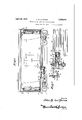
- Figure 1 is a side elevation of a railroad car with parts broken.away showing the refrigerating apparatus
- Figure 2 is a bottomplan in detail of the refxigerating apparatus removed from the car;
- Figure 3 is a plan view of the expansion coils taken on the line 3-3 of Figure 1;
- Figure 4 is a plan view looking downward on the line 44 of Figure 1;
- Figure 5 is a verticalsection on 5-5 of Fi re 3, showing the coils
- igure 6 is a section showing a modifica- 50 tion of Figure 5.
- Figure 7 is a top plan of the modification shown in Figure 6.
- nmeral 1 designates a railroad car.
- a clutch lever 17 controls a clutch 18, which is slidably mounted in a ke -way on the shaft 11, the belt pulley 12 aving' a r'atchet face 19 to engage.with said clutch 18.
- the same structure is present in the clutch 7 7, controlling the motor 5.
- a lever 7 is provided for throwing the clutch 7 into and out of engagement with a collr 20 mounted on the end of the crank arm9 which extends from the cylindr wall 10 ad acent the motor 5; the collar 20 having a ratchet face 21 t0 engage the elutch 7.
- a byas sage 22 leading into an.oil separator 23.
- xtending from the oil separator 23 is a pipe formed into a series of cooling coils 24:, which,
- a chemical retainer 25 in this particular case ammonia.
- a pipe 26 leading from said retainer is an expansion valve 27.
- the pipe 26 extends beneath the car 1 to the extreme end where it enter's the car 1 closely adjacent the end wall 28 thereof, and extends to a point closely adjacent the roof or top wall 29 where it enters a tank 30, being formed in said tank into a series of coils, as shown in Fi re 5 thecoils extending in a vertical direction, or a in Figure 6 in the form of a helix.
- the pipe 26 extends the length of the car 1, adjacent the roof 2Qtherkof and is returnedto form a net:
- theclutch lever 17 will be operated to throw the clutch 18 into engagement with the compressor and the clutch lever 7 will be operated to throw the clutch 7 out of engagement with the motor 5 if the car is in motion or,aboutto start.
- the belt 13, which connects the axle 15 and the belt 12 will cause the compressor 6 to operate as the axle 15 revolves.
- the clutch lever 17 will throw the clutch 18 out of engagement with the belt 12, and the operation of the clutch lever 7 will throw the clutch 7 into engagement with the collar 20 and the motor 5, whereupon the motor being turned on, the compressor will operate.
- the operation of the compressor 6 will force the refrigerant Such as compressd ammonia gas through the oil separator 23 and cooling coils 24 until it reaches the chemical retainer 25, which, in this case, contains ammonia.
- the ammonia largely liquid,.is forced out of the chemical retainer 25 through an expansion valve 27 under pressure, and as it leaves the expansion valve 27 it will expand, absorbing heat and assume its gaseous form.
- the semiliquid ammonia passes into the coils in the tank 30 and absorbs th'e.heat collected from the refrigerator interior.
- Water ma; be placed in thetank if it is desired to form ice, or brine may be placed thereinand the brine be conducted to other vess els in which water is placed to form ice.
- the semi- 4 liquid passes froni the tank 30 through a se ries of coils at the top of the car t0 a second ank 33 located at the opposite end of the car.
- he coils continue to cool the interior of the car by absorbing heat from the hottest.part, namely; the moi, and causing the cooled air to drop, ths cooling the stratas of air below and setting up a umform circulation.
- the water or brine may be placed infthe tank 33 as described in connection with the tank 30, and from the tank 33 the semi-liquid,
- The.gas enters the compresser through an opening 40 at the rear of the;outlet port 34.
- the gas will fill the'cylinder 10 at the 1ear of said piston 8, and upon the up-stroke the gas will be fo'rd through a by-passage 41 to collect below the piston 8 in the lower portion of the cylinder 10.
- the gas Upon the downstroke of the piston, the gas will becompressed and forced out through the outlet* port 34, and throughthe system as described.
- the modification, gas shown in Figures 6 and 7, may be utilized where it is desired to place receptacles wi-thin the coils for forming ice. It is to be noted'tha't all structure that is not needed for actually cooling the interior of the car is placed without the same, and that the placing of the coils within the car along with the tanks is so arranged as to occupy a minimum of space and yet provide the greatest efliciency from the cooling system.
- Another advantage of having the over-head coils is that upon the door 35 being opened, the car may be re-refrigerated in much less time than formerly, in that it is not necessary to depend upon the cooled air circulatmg from one end or both ends alone, but circulatien and cooiing wiil be set up immediately opposite the door 35, which, after having been opened, Wil1 normaHy be the warmest portion of the car.
- a refrigerating compartment In a refrigerating system for railroad cars, a refrigerating compartment, pipes ieading into and out of said compartment, a serics of coils at each end of said compartn1ent, the pipes leading into and out of said compartmcnt connected to said cols, a coil adjacent the top of the compartment and connected to the two end coiis, and condensing and compressing means beneath said compartment and connected to the said pipes ieading into and out of said compartment.
- a refrigerator car an expansion coil at each end of the car, an expansion coil adjacent the ceiling of said car said celing coil receiving thedischarge refrigerant from one end coil and discharging into the other end coil, and compressor and condensing'means located beneath the car connected with the discharge of one end coil and the intake of the other end coil whereby a continuous circuit of refrigerant is forced through one end coil, the ceiling coil and the other end coil, successively, as specified.
- a compressor 1ocated outside and .beneath the car means foi driving the compressor, means for selectively connecting the compressor with the driving means and the traction means of the car, a condensor coil lo'cated outside and beneath the car exposed to air passing thercunder, an expansion coil in the car, positioned in a plane paral1el with and closely adjacent to the ceiling of the car the convolutions of said expansion coil extending lengthwise of the car and being substantiaily coextensive therewith, and means cohnectin the condensor coil, compressor and expans1on coil in series inclnding an expansion valve.
Description
April 1932- *J. M. LE MIEUX 1,856,041
REFRIGEHATOR UNIT FOR RAILROAD CARS Filed Au 28, 1929 2 Sheets-Sheet 1 April 26, 1932. J. M. LE MIEUX REFRIGERTOR UNIT FOR RAILROAD CARS File Aug. 28, 1929 2 Sheets-Sheet uNn Patented Apr. 26, 1932 PATENT OFFICE JOHN M. LE MIEUX; OF NEW ORLEANS, LOUISANA BEFBGERATOB UNIT FOR. RAILROAZD CARS Application flled August 28, 1929. 8eral No. 389,013.
This invention relates to improVements in a system for controlling the temperature in railroad cars.
V The prime object of my invention is to pro- Vide a cooling apparatus that will occupy a minimum amount of space within the usual railroad car, and at the same time, fonction more eficiently than the apparatus now in use.
Another Object is to provide a structure that will make ice, as well as control the temperatures of the car.
Stili another object is to provide an even v temperature at all times throughout the car.
It is weil known that the usual refrigerator car travels long distances, and passes through varying temperatures and climates.
It is my object to provide means for controlling the refrigeratingapparatus so that the fi0W of the refrigerant material Will be in accordance with the temperature in the interior of the car and surrounding atmosphere.
This would result in a great saving of material and wear and tear on the apparatus and, at the same time, isure the preservation of the foodstuiia or other ommodities shipped in the car.
Another object is to utilize the power from the moving car when the same is in motion, and to provide means for operating the reingeratmg apparatus when the car is at a standstiil.
Other objecte will be disclosed in the spacification and dra'winge made a part of this application.
In the drawings: Figure 1 is a side elevation of a railroad car with parts broken.away showing the refrigerating apparatus;
Figure 2 is a bottomplan in detail of the refxigerating apparatus removed from the car; A
Figure 3 is a plan view of the expansion coils taken on the line 3-3 of Figure 1;
Figure 4 is a plan view looking downward on the line 44 of Figure 1;
Figure 5 is a verticalsection on 5-5 of Fi re 3, showing the coils;
igure 6 is a section showing a modifica- 50 tion of Figure 5; and
Figure 7 is a top plan of the modification shown in Figure 6.
Referring to the drawings in detail, in Which similar refere'nce characters designate corresponding parts throughout the sveral views; nmeral 1 designates a railroad car.
of the usual construction having trucks 2 with wheels 3 and axles 15 connecting the Wheels 3. Suspended between the trucks 2 is a frame on which is supported a motor 5 and a compressor 6 with a clutch member 7 betWeen the compreeeor 6 and motor 5. A piston 8 connected to a crank arm 9, slides in a cylinder 10. The clank arm 9 eXtends beyond the wall of the cylinder 10 to form a shaft 11 on which is freely mounted a belt pulley 12, which is connected by a belt 13 t0 a second'belt pulley 14 secured to the axle 15 by a screw or boit 16.
A clutch lever 17 controls a clutch 18, which is slidably mounted in a ke -way on the shaft 11, the belt pulley 12 aving' a r'atchet face 19 to engage.with said clutch 18. The same structure is present in the clutch 7 7, controlling the motor 5. A lever 7 is provided for throwing the clutch 7 into and out of engagement with a collr 20 mounted on the end of the crank arm9 which extends from the cylindr wall 10 ad acent the motor 5; the collar 20 having a ratchet face 21 t0 engage the elutch 7.
At the end of the cylinder 10 is a byas sage 22 leading into an.oil separator 23. xtending from the oil separator 23 is a pipe formed into a series of cooling coils 24:, which,
in turn, lead to a chemical retainer 25, in this particular case ammonia. Just beyond the chemical retainer 25, in a pipe 26 leading from said retainer, is an expansion valve 27. The pipe 26 extends beneath the car 1 to the extreme end where it enter's the car 1 closely adjacent the end wall 28 thereof, and extends to a point closely adjacent the roof or top wall 29 where it enters a tank 30, being formed in said tank into a series of coils, as shown in Fi re 5 thecoils extending in a vertical direction, or a in Figure 6 in the form of a helix.
From the last turn of the coils, the pipe 26 extends the length of the car 1, adjacent the roof 2Qtherkof and is returnedto form a net:
work of coils, covering the entire area beneath the roof 29. 1
It is to be noted that these convolutions of the coils are in a common horizontal plane. The last convolution of the coil will be adjacent the side wall 31, which is the side opwhich the first length of posite that alon will be bent parallel with pipe extends an the ends of the convolutions parallel to the 'is repeate A door permits ingress and egress to and from the car 1. Positioned in a line of thecirculation at ends 28 and 32, respectively, are thermostatic valve controls 36 and 37. The thermostatic valve controls are connected to valves 38 and 39 so that upon the rise or fall of the temperature Within the car the respective valves 38 and 39 will be opened or closed accordingly, to control the fibw of the refrigerant material.
As actually operated, theclutch lever 17 will be operated to throw the clutch 18 into engagement with the compressor and the clutch lever 7 will be operated to throw the clutch 7 out of engagement with the motor 5 if the car is in motion or,aboutto start.
The belt 13, which connects the axle 15 and the belt 12 will cause the compressor 6 to operate as the axle 15 revolves.
Should the car be at a standstill or shunted to a siding, the clutch lever 17 will throw the clutch 18 out of engagement with the belt 12, and the operation of the clutch lever 7 will throw the clutch 7 into engagement with the collar 20 and the motor 5, whereupon the motor being turned on, the compressor will operate.
The operation of the compressor 6 will force the refrigerant Such as compressd ammonia gas through the oil separator 23 and cooling coils 24 until it reaches the chemical retainer 25, which, in this case, contains ammonia. The ammonia largely liquid,.is forced out of the chemical retainer 25 through an expansion valve 27 under pressure, and as it leaves the expansion valve 27 it will expand, absorbing heat and assume its gaseous form.
The semiliquid ammonia passes into the coils in the tank 30 and absorbs th'e.heat collected from the refrigerator interior. Water ma; be placed in thetank if it is desired to form ice, or brine may be placed thereinand the brine be conducted to other vess els in which water is placed to form ice. The semi- 4 liquid passes froni the tank 30 through a se ries of coils at the top of the car t0 a second ank 33 located at the opposite end of the car.
he coils continue to cool the interior of the car by absorbing heat from the hottest.part, namely; the moi, and causing the cooled air to drop, ths cooling the stratas of air below and setting up a umform circulation.
The water or brine may be placed infthe tank 33 as described in connection with the tank 30, and from the tank 33 the semi-liquid,
( whi ch, by this time, is practically gas again due to the absorption of heat, passes out of the car at the farthest end wall 32, so that the floor space will not be occupied with the pipe, and the temperaturewithin the car will not be' further reduced due to the passage of ammonia gas which'has practically lost all of its heat absorbing qualities. The passage of the pipe beneath the car exposes the same to the air, and upon its reachingthe compressor it is in a gascons form once more.
,The.gas enters the compresser through an opening 40 at the rear of the;outlet port 34.
,Up0n the piston 8 operating on the down- Stroke, the gas will fill the'cylinder 10 at the 1ear of said piston 8, and upon the up-stroke the gas will be fo'rd through a by-passage 41 to collect below the piston 8 in the lower portion of the cylinder 10. Upon the downstroke of the piston, the gas will becompressed and forced out through the outlet* port 34, and throughthe system as described.
The modification, gas shown in Figures 6 and 7, may be utilized where it is desired to place receptacles wi-thin the coils for forming ice. It is to be noted'tha't all structure that is not needed for actually cooling the interior of the car is placed without the same, and that the placing of the coils within the car along with the tanks is so arranged as to occupy a minimum of space and yet provide the greatest efliciency from the cooling system.
By having tanks placed in both ends, a circulation may be established from both ends extending-towardthe middle, and the great. objection of having the source of refrigeratioxi only' at one end, thus depending upon radiation or circulation to properly refrigerate the car, is overcome.
Further, by connecting the two tanks with over-head fiat coils, a uniform temperature 'is created between the two tanks, and, in addition to the two cir0ulationsset up at both ends, a circulation extending from the top. between thetwo sides of the car is set up, thus thoroughly refngeratmgall parts of the car.
Another advantage of having the over-head coils, is that upon the door 35 being opened, the car may be re-refrigerated in much less time than formerly, in that it is not necessary to depend upon the cooled air circulatmg from one end or both ends alone, but circulatien and cooiing wiil be set up immediately opposite the door 35, which, after having been opened, Wil1 normaHy be the warmest portion of the car.
While I have described my invention in a specific form, it is to be understood that various changes may be made in the construction and arrangement of the parts as Well as in the proportion thereof withont departing from the spirit and scope of the invention to be defined in the claims appended to and forming a part of this specification.
What I daim is:
i. In a refrigerating system for railroad cars, a refrigerating compartment, pipes ieading into and out of said compartment, a serics of coils at each end of said compartn1ent, the pipes leading into and out of said compartmcnt connected to said cols, a coil adjacent the top of the compartment and connected to the two end coiis, and condensing and compressing means beneath said compartment and connected to the said pipes ieading into and out of said compartment.
2. ][n a refrigerator car, an expansion coil at each end of the car, an expansion coil adjacent the ceiling of said car said celing coil receiving thedischarge refrigerant from one end coil and discharging into the other end coil, and compressor and condensing'means located beneath the car connected with the discharge of one end coil and the intake of the other end coil whereby a continuous circuit of refrigerant is forced through one end coil, the ceiling coil and the other end coil, successively, as specified.
3. in a refrigerator car, an expansion coil at each end ofthe car, an expansion coil adjacent the ceiiing of said car, said ceiling coil receiving the discharge refrigerant from one end coil and including convolutions extend ing between the end coils and discharging into the other end coil, and compresser and condenser menus located beneath the car connected with the discharge of one end coil and the intake of the other end coil whereb) a continuous circuit of refrigerant is forced throngh one end-coil, the ceiling coil and the other end coil, succesaively, as specified.
4. In a refrigerator car, au expansion coil at each end of the car, an expansion coil adjacent the ceiling of said car, said ceiling coil receiving the discharge refrigerant from one end coil and discharging into the other end coil, and compressor and Condenser means connected with the discharge-of one and coil and the ii1take of the other end coil whereby a continuous circuit of refri erant is forced through one end coil, the ce1ling coil and the other end coil, successivcly, as specified, and means for throwing said compresser into and out of operative engagement with the propelling means of said car.
5. In a refrigerator car, an expansion coil adjacent and substantiafly co-extensive with denser means carried outside of and beneath the car connected with the coil whereby a continuons circuit of refrigerant is forced through the ceiling coil as specified.
6. In a refrigerator car, a compressor 1ocated outside and .beneath the car, means foi driving the compressor, means for selectively connecting the compressor with the driving means and the traction means of the car, a condensor coil lo'cated outside and beneath the car exposed to air passing thercunder, an expansion coil in the car, positioned in a plane paral1el with and closely adjacent to the ceiling of the car the convolutions of said expansion coil extending lengthwise of the car and being substantiaily coextensive therewith, and means cohnectin the condensor coil, compressor and expans1on coil in series inclnding an expansion valve.
In testimony whereof I afiix my si ature.
JOHN M. MI UX.
Priority Applications (1)
| Application Number | Priority Date | Filing Date | Title |
|---|---|---|---|
| US389013A US1856041A (en) | 1929-08-28 | 1929-08-28 | Refrigerator unit for railroad cars |
Applications Claiming Priority (1)
| Application Number | Priority Date | Filing Date | Title |
|---|---|---|---|
| US389013A US1856041A (en) | 1929-08-28 | 1929-08-28 | Refrigerator unit for railroad cars |
Publications (1)
| Publication Number | Publication Date |
|---|---|
| US1856041A true US1856041A (en) | 1932-04-26 |
Family
ID=23536464
Family Applications (1)
| Application Number | Title | Priority Date | Filing Date |
|---|---|---|---|
| US389013A Expired - Lifetime US1856041A (en) | 1929-08-28 | 1929-08-28 | Refrigerator unit for railroad cars |
Country Status (1)
| Country | Link |
|---|---|
| US (1) | US1856041A (en) |
-
1929
- 1929-08-28 US US389013A patent/US1856041A/en not_active Expired - Lifetime
Similar Documents
| Publication | Publication Date | Title |
|---|---|---|
| US2323511A (en) | Refrigerating and air conditioning apparatus | |
| CN101097099A (en) | Refrigerant cycle device with ejector | |
| US2270810A (en) | Condenser | |
| US2693682A (en) | Refrigerating system with defrosting arrangement | |
| US2046314A (en) | Room cooling unit | |
| US1856041A (en) | Refrigerator unit for railroad cars | |
| CN1325869C (en) | Heat pipe cold guide device and cold storage body and freezer with said device | |
| US2044330A (en) | Air conditioner | |
| US1352533A (en) | Traveling refrigerating plant | |
| US2336066A (en) | Air conditioning apparatus | |
| US2738655A (en) | Unitary refrigerating air conditioner | |
| US2469648A (en) | Automatic control for refrigerators | |
| US1492512A (en) | Cooling and heating system | |
| US2170992A (en) | Air conditioning | |
| US2302189A (en) | Refrigeration apparatus | |
| US2668421A (en) | Refrigerator car with fan and brine circulating system | |
| US668033A (en) | Refrigerator-car. | |
| US1717459A (en) | Refrigerator | |
| US1838259A (en) | Pump for refrigerating apparatus | |
| US276952A (en) | Refrigerator-car | |
| US1405319A (en) | Refrigerating apparatus | |
| US1602462A (en) | Purging system for refrigerating plants | |
| US191232A (en) | Improvement in air-cooling apparatus | |
| US1499489A (en) | Refrigerating apparatus | |
| US1823858A (en) | Compressor-condenser unit |