US1856030A - Wall insert - Google Patents
Wall insert Download PDFInfo
- Publication number
- US1856030A US1856030A US576363A US57636331A US1856030A US 1856030 A US1856030 A US 1856030A US 576363 A US576363 A US 576363A US 57636331 A US57636331 A US 57636331A US 1856030 A US1856030 A US 1856030A
- Authority
- US
- United States
- Prior art keywords
- plate
- plates
- plaster
- rear plate
- edges
- Prior art date
- Legal status (The legal status is an assumption and is not a legal conclusion. Google has not performed a legal analysis and makes no representation as to the accuracy of the status listed.)
- Expired - Lifetime
Links
Images
Classifications
-
- E—FIXED CONSTRUCTIONS
- E04—BUILDING
- E04F—FINISHING WORK ON BUILDINGS, e.g. STAIRS, FLOORS
- E04F13/00—Coverings or linings, e.g. for walls or ceilings
- E04F13/07—Coverings or linings, e.g. for walls or ceilings composed of covering or lining elements; Sub-structures therefor; Fastening means therefor
- E04F13/08—Coverings or linings, e.g. for walls or ceilings composed of covering or lining elements; Sub-structures therefor; Fastening means therefor composed of a plurality of similar covering or lining elements
- E04F13/12—Coverings or linings, e.g. for walls or ceilings composed of covering or lining elements; Sub-structures therefor; Fastening means therefor composed of a plurality of similar covering or lining elements of metal or with an outer layer of metal or enameled metal
-
- Y—GENERAL TAGGING OF NEW TECHNOLOGICAL DEVELOPMENTS; GENERAL TAGGING OF CROSS-SECTIONAL TECHNOLOGIES SPANNING OVER SEVERAL SECTIONS OF THE IPC; TECHNICAL SUBJECTS COVERED BY FORMER USPC CROSS-REFERENCE ART COLLECTIONS [XRACs] AND DIGESTS
- Y10—TECHNICAL SUBJECTS COVERED BY FORMER USPC
- Y10S—TECHNICAL SUBJECTS COVERED BY FORMER USPC CROSS-REFERENCE ART COLLECTIONS [XRACs] AND DIGESTS
- Y10S52/00—Static structures, e.g. buildings
- Y10S52/06—Toothed connecting means
Definitions
- the invention relates to a wall insert or face plate preferably made of sheet metal and enamelled, to be used as a facin for plastered walls, the product being 0 the type having rearwardly projecting portions which are embedded in the plaster before it is hardened, and which serve to support the face plate and hold it in position on the wall.
- the facing tiles and the like which are now in use are not sufliciently secured to the plaster and are apt to work loose and drop out, and also with the majority of these prior constructions the plaster is in full contact with the rear side of the late so that if the plaster is not even and dirt, the face plates can not be perfectly aligned without the greatest care in placing them.
- the facing plates made in accordance with the invention are provided in addition to the front plate or face plate proper, with a rear plate which is permanently and rigidly secured to the front plate preferably in a manner which obviates the necessity for soldering or welding, i. e., by clinching.
- This rear plate is preferably flat and parallel to the front plate which it supports by means of projecting tongues which are most conveniently formed by punching them out of the metal of the rear plate, providing holes for the entrance of the plaster in setting the tiles.
- These tongues are preferably pointed and may also be provided with additional perfo rations for the admission of plaster on both sides of the tongues.
- the pocket formed between the plates provides a receptacle for the plaster which is displaced in inserting or seating the tile, permitting the tile to be secured in any position into which it may be pressed or forced, making it easy to align the tiles.
- the rear plate with its pointed tongues is also of advantage in that it provides a support throughout the surface of the tile which prevents sagging when the tile is heated in applying the enamelled surface and the pointed configuration of the tongues is of further advantage in that the contact of the rear plate with the front plate is reduced to the minimum so that the heat which the rear plate abstracts from the front plate in enameling when the enamelled surface must be heated to a hi h temperature, is likewise reduced facilitatlng the process of enamelling the tiles.
- tongues thus punched out of the rear plate and engaging the front plate, spacing the rear plate from the front plate, are of 6 particular advantage in forming the tile without soldering or welding. These tongues serve most effectively in combination with the turned edges of the front and rear plates as a counter support spacing the plates apart with said edges in close contact, one with the other, as hereinafter described.
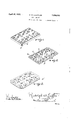
- Figure 1 is a perspective view of a completed tile showing the rear surface upwardly disposed.
- Figure 2 is a perspective view of the rear plate showing the bottom or inside surface of the same turned upwardly toward the observer.
- Figure 3 is a similar view of a modified form of rear plate.
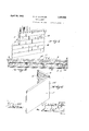
- Figure 4 is a fragmentary horizontal section of a plastered wall showing the tiles of the invention attached thereto also in section.
- Figure 5 is an elevation of a wall covered with the face plates of the invention.
- Figure 6 is an elevation of a corner tile constructed in accordance with the invention.
- the con struction shown comprises a front plate 1 and rear plate 2.
- the latter in the preferred form of the invention shown is perforated at 3, 4 to admit the soft plaster when the tile is seated as aforesaid.
- the front plate 1 and rear plate 2 being most conveniently of sheet metal, the perforations 3, L and the edges of the rear plate at 6, as hereinafter described are to the best advantage formed by punching and die pressing.
- the perforations are shown as triangular, although they may be otherwise shaped and in the formation of part of these perforations indicated by reference character 4, the metal which is dlsplaced is left attached at one side of the triangle forming projecting tongues 7 which in the preferred form of the invention are pointed at 8, as already suggested. These tongues are bent at a sharp angle to the plane of the plate, being preferably turned at right angles thereto as indicated in Fi re 2 and forwardly toward the position 0 the front plate.
- the alternate perforations or the remainder of the perforations 3 may to the best advantage be formed by severing the metal on all sides so that there are no projecting tongues. This permits the plaster which is displaced in seating the tile to enter more freely into the cavity between the plates, permitting the face plates to be aligned with ease.
- edges of the rear plates 2, indicated by reference character 6, are preferably turned.
- the edges 6 are turned in the general direction in which the tongues 7 are deflected from the plane of the plate.
- the edges 6 are preferably inclined outwardly at an obtuse angle away from the center of the plate, and as aforesaid in the direction of tongues 7, as best shown in Figure 4.
- the former In attaching the front plates to the rear plates the former are laid in contact with the points 8 of the tongues 7, and have their edges 9 in suitable relationto the edges 6 of the rear plates, the said edges 9 are then clinched or turned over about the inclined edges 6.
- the edges 9 being turned at an acute angle to the plane of the plate 1, so that they overlie and enclose edges 6 which are turned at an obtuse angle to the plane of the plate 2, whereby the front plates are permanently attached to the rear plates and supported and spaced therefrom by the points 7, which apply to the front plates 6 forward supporting pressure counter to that applied by clinching the edge plate.
- the plates are then permanently and rigidly connected without the necessity for welding, soldering or riveting.
- the edges 6 of the rear plate may be notched in saw tooth form, still further reducing the area of contact of the front and rear plates, or these edges may be left straight as indicated in 6 in Figure 3.
- the tile is cleaned and then coated with porcelain and placed horizontally in an oven to bake, the rear plates being downward.
- the lugs or tongues 7 support the front plate by means of the points 8 contacting the rear surface of the latter and preventing sagging and consequent disalignment of the p ate.
- Flgures 4 and 5 show the facing plates attached to a plaster wall indicated by reference character 10, the plaster being as shown supported on wooden laths 11, though this is not essential to the invention, the front plates 1 being coated with vitreous enamel 12, which may to the best advantage be arranged and marked at 14 to resemble ceramic tiling.
- FIG. 6 shows a corner tile 15 which is otherwise closely similar to the tiles just described, having a front plate 1, and a rear plate 2 attached, as already described, in connection with the Figures 1 to 5. This late is aflixed to the plaster as already descri ed to cover the projecting corner of the wall.
- the inserts made in accordance with the invention are most securely affixed to the plaster by the entrance of the plaster when soft through the apertures 3 and 4. This displacement of the plaster also provides for the convenient alignment of the tile which can be thus secured in almost any osition into which they may be pressed, an it further gives added security and ease of application.
- a wall insert for plaster walls comprising a front plate and a rear plate, the latter having a plurality of projecting members distributed throughout its area and engaging the front plate to space and support the same, means for connecting the plates at their edges, the rear plate being perforated to admit the soft plaster which enters as the plate is seated in the surface of the wall.
- a wall insert for plastered walls comprising a front plate and a rear plate, the rear plate having integral deflected portions distributed throughout its area engaging the front plate to support the same, the edges of the plates being deflected and engaged oppositel to the engagement of the front late by the eflected portion to connect the p ates together.
- a wall insert for plastered Walls comprisin afront plate and a rear plate which are substantially parallel, one to the other and spaced apart, the rear plate having integral deflected portions distributed throughout its area engaging the frontplate to support the same, the ed es of the plates being deflected and engage oppositely to the engagement of the front plate by the deflected portion to connect the plates together.
- a wall insert for plastered walls comprising a front plate and a rear plate which are substantially parallel one to the other and spaced apart, the rear plate having integral deflected portions distributed throughout its area engaging the front plate to support the same, the edges of the plates being deflected and engaged oppositely to the engagement of the front plate by the deflected portion to connect the plates together, the deflected portions also serving as a spacing means for the plates.
- a face plate for plastered walls comprisin a front plate and a rear plate, which are su stantially parallel, the rear plate having pointed lugs distributed throughout. its area, engaging the front plate to support the same, the edges of the plates being engaged by clinching to connect the plates together, the lugs also serving as a spacing means for the plates.
- a wall insert for plastered walls comprising a front plate and a rear plate, which are substantially parallel, the rear plate having integral deflected portions in the form of pointed In S distributed throughout its area, engaging the front plate to support the same, the edges of the plates being deflected and engaged by clinching to connect the plates together, the lugs also serving as a spacing means for the plates.
- a wall insert for plaster walls having a front and rear plate, members integral with the rear plate for spacing the plates apart and engaging the front plate at points distributed throughout its area, the front plate being coated with vitreous enamel.
- a wall insert for plaster walls having a front and rear plate, means integral with the rear plate for spacing the plates apart engaging the front plate at points distributed throughout its area, said means being pointed, the points engaging the front plate, the front plate being coated with vitreous enamel, the edges of the plates being interengaged to hold them in the assembled relation.
- a face plate for plaster walls having a front and rear plate, means integral with the rear plate for spacin the plates apart and engaging the front p ate at points distributed throughout its area, said means defing pointed, the points engaging the front
Description
April 26, 1932. R. w. LOEFFLER WALL INSERT Filed Nov. 20, 1931 2 Sheets-Sheet l ill-ii.
April 26, 1932. R LQEFFLER 1,856,030
WALL INSERT Filed Nov. 20, 1931 2 Sheets-Sheet 2 Patented Apr. 26, 1932 UNITED STATES PATENT OFFICE WALL INSERT Application filed November 20, 1931. Serial No. 576,363.
The invention relates to a wall insert or face plate preferably made of sheet metal and enamelled, to be used as a facin for plastered walls, the product being 0 the type having rearwardly projecting portions which are embedded in the plaster before it is hardened, and which serve to support the face plate and hold it in position on the wall. The facing tiles and the like which are now in use are not sufliciently secured to the plaster and are apt to work loose and drop out, and also with the majority of these prior constructions the plaster is in full contact with the rear side of the late so that if the plaster is not even and dirt, the face plates can not be perfectly aligned without the greatest care in placing them.
The facing plates made in accordance with the invention are provided in addition to the front plate or face plate proper, with a rear plate which is permanently and rigidly secured to the front plate preferably in a manner which obviates the necessity for soldering or welding, i. e., by clinching. This rear plate is preferably flat and parallel to the front plate which it supports by means of projecting tongues which are most conveniently formed by punching them out of the metal of the rear plate, providing holes for the entrance of the plaster in setting the tiles. These tongues are preferably pointed and may also be provided with additional perfo rations for the admission of plaster on both sides of the tongues. Not only is the engage ment of the perforated rear plate with the surface of the plaster much more effective than with the old type, but the pocket formed between the plates provides a receptacle for the plaster which is displaced in inserting or seating the tile, permitting the tile to be secured in any position into which it may be pressed or forced, making it easy to align the tiles.
The rear plate with its pointed tongues is also of advantage in that it provides a support throughout the surface of the tile which prevents sagging when the tile is heated in applying the enamelled surface and the pointed configuration of the tongues is of further advantage in that the contact of the rear plate with the front plate is reduced to the minimum so that the heat which the rear plate abstracts from the front plate in enameling when the enamelled surface must be heated to a hi h temperature, is likewise reduced facilitatlng the process of enamelling the tiles.
The tongues thus punched out of the rear plate and engaging the front plate, spacing the rear plate from the front plate, are of 6 particular advantage in forming the tile without soldering or welding. These tongues serve most effectively in combination with the turned edges of the front and rear plates as a counter support spacing the plates apart with said edges in close contact, one with the other, as hereinafter described.
The opposite thrust of these tongues and edges giving a most effective locking or clinching 0 the. plates whereby they are permanently and rigidly connected.
In the drawings:
Figure 1 is a perspective view of a completed tile showing the rear surface upwardly disposed.
Figure 2 is a perspective view of the rear plate showing the bottom or inside surface of the same turned upwardly toward the observer.
Figure 3 is a similar view of a modified form of rear plate.
Figure 4 is a fragmentary horizontal section of a plastered wall showing the tiles of the invention attached thereto also in section.
Figure 5 is an elevation of a wall covered with the face plates of the invention.
Figure 6 is an elevation of a corner tile constructed in accordance with the invention.
Referring to the drawings by numerals, each of which is used to indicate the same or similar parts in the different figures, the con struction shown comprises a front plate 1 and rear plate 2. The latter in the preferred form of the invention shown is perforated at 3, 4 to admit the soft plaster when the tile is seated as aforesaid. The front plate 1 and rear plate 2 being most conveniently of sheet metal, the perforations 3, L and the edges of the rear plate at 6, as hereinafter described are to the best advantage formed by punching and die pressing. The perforations are shown as triangular, although they may be otherwise shaped and in the formation of part of these perforations indicated by reference character 4, the metal which is dlsplaced is left attached at one side of the triangle forming projecting tongues 7 which in the preferred form of the invention are pointed at 8, as already suggested. These tongues are bent at a sharp angle to the plane of the plate, being preferably turned at right angles thereto as indicated in Fi re 2 and forwardly toward the position 0 the front plate. The alternate perforations or the remainder of the perforations 3 may to the best advantage be formed by severing the metal on all sides so that there are no projecting tongues. This permits the plaster which is displaced in seating the tile to enter more freely into the cavity between the plates, permitting the face plates to be aligned with ease.
The edges of the rear plates 2, indicated by reference character 6, are preferably turned. The edges 6 are turned in the general direction in which the tongues 7 are deflected from the plane of the plate. The edges 6 are preferably inclined outwardly at an obtuse angle away from the center of the plate, and as aforesaid in the direction of tongues 7, as best shown in Figure 4.
In attaching the front plates to the rear plates the former are laid in contact with the points 8 of the tongues 7, and have their edges 9 in suitable relationto the edges 6 of the rear plates, the said edges 9 are then clinched or turned over about the inclined edges 6. The edges 9 being turned at an acute angle to the plane of the plate 1, so that they overlie and enclose edges 6 which are turned at an obtuse angle to the plane of the plate 2, whereby the front plates are permanently attached to the rear plates and supported and spaced therefrom by the points 7, which apply to the front plates 6 forward supporting pressure counter to that applied by clinching the edge plate. The plates are then permanently and rigidly connected without the necessity for welding, soldering or riveting.
It will be noted from observation of Figure 2 that the edges 6 of the rear plate may be notched in saw tooth form, still further reducing the area of contact of the front and rear plates, or these edges may be left straight as indicated in 6 in Figure 3. When the tile has been thus completed, it is cleaned and then coated with porcelain and placed horizontally in an oven to bake, the rear plates being downward. During the baking process the lugs or tongues 7 support the front plate by means of the points 8 contacting the rear surface of the latter and preventing sagging and consequent disalignment of the p ate.
The drawing, Figure 6, shows a corner tile 15 which is otherwise closely similar to the tiles just described, having a front plate 1, and a rear plate 2 attached, as already described, in connection with the Figures 1 to 5. This late is aflixed to the plaster as already descri ed to cover the projecting corner of the wall.
The inserts made in accordance with the invention are most securely affixed to the plaster by the entrance of the plaster when soft through the apertures 3 and 4. This displacement of the plaster also provides for the convenient alignment of the tile which can be thus secured in almost any osition into which they may be pressed, an it further gives added security and ease of application.
The advantages of the tongues 7 supporting the front plate and preventing warping I and sagging of the same and the pointed formation .of these tongues whereby the least heat is extracted from the highly heated enamelled surface have been quite fully discussed, as will be apparent from the drawings and description.
have thus described specifically and in detail a face plate for plaster walls embodying the features of the invention in the preferred form, the description being specific and in detail, in order that the manner of constructing, applying, operating and using the invention may be fully understood, however, the specific terms herein are used descriptively rather than in a limitin sense, the scope of the invention being det ined in the claims.
What I claim as new and desire to secure by Letters Patent is: Y
1. A wall insert for plaster walls compris ing a front plate and a rear plate, the latter having a plurality of projecting members distributed throughout its area and engaging the front plate to space and support the same, means for connecting the plates at their edges, the rear plate being perforated to admit the soft plaster which enters as the plate is seated in the surface of the wall.
2. A wall insert for plastered walls comprising a front plate and a rear plate, the rear plate having integral deflected portions distributed throughout its area engaging the front plate to support the same, the edges of the plates being deflected and engaged oppositel to the engagement of the front late by the eflected portion to connect the p ates together.
3. A wall insert for plastered Walls comprisin afront plate and a rear plate which are substantially parallel, one to the other and spaced apart, the rear plate having integral deflected portions distributed throughout its area engaging the frontplate to support the same, the ed es of the plates being deflected and engage oppositely to the engagement of the front plate by the deflected portion to connect the plates together.
4. A wall insert for plastered walls comprising a front plate and a rear plate which are substantially parallel one to the other and spaced apart, the rear plate having integral deflected portions distributed throughout its area engaging the front plate to support the same, the edges of the plates being deflected and engaged oppositely to the engagement of the front plate by the deflected portion to connect the plates together, the deflected portions also serving as a spacing means for the plates.
5. A face plate for plastered walls comprisin a front plate and a rear plate, which are su stantially parallel, the rear plate having pointed lugs distributed throughout. its area, engaging the front plate to support the same, the edges of the plates being engaged by clinching to connect the plates together, the lugs also serving as a spacing means for the plates.
6. A wall insert for plastered walls comprising a front plate and a rear plate, which are substantially parallel, the rear plate having integral deflected portions in the form of pointed In S distributed throughout its area, engaging the front plate to support the same, the edges of the plates being deflected and engaged by clinching to connect the plates together, the lugs also serving as a spacing means for the plates.
7. A wall insert for plaster walls having a front and rear plate, members integral with the rear plate for spacing the plates apart and engaging the front plate at points distributed throughout its area, the front plate being coated with vitreous enamel.
8. A wall insert for plaster walls having a front and rear plate, means integral with the rear plate for spacing the plates apart engaging the front plate at points distributed throughout its area, said means being pointed, the points engaging the front plate, the front plate being coated with vitreous enamel, the edges of the plates being interengaged to hold them in the assembled relation.
9. A face plate for plaster walls having a front and rear plate, means integral with the rear plate for spacin the plates apart and engaging the front p ate at points distributed throughout its area, said means defing pointed, the points engaging the front
Priority Applications (1)
| Application Number | Priority Date | Filing Date | Title |
|---|---|---|---|
| US576363A US1856030A (en) | 1931-11-20 | 1931-11-20 | Wall insert |
Applications Claiming Priority (1)
| Application Number | Priority Date | Filing Date | Title |
|---|---|---|---|
| US576363A US1856030A (en) | 1931-11-20 | 1931-11-20 | Wall insert |
Publications (1)
| Publication Number | Publication Date |
|---|---|
| US1856030A true US1856030A (en) | 1932-04-26 |
Family
ID=24304123
Family Applications (1)
| Application Number | Title | Priority Date | Filing Date |
|---|---|---|---|
| US576363A Expired - Lifetime US1856030A (en) | 1931-11-20 | 1931-11-20 | Wall insert |
Country Status (1)
| Country | Link |
|---|---|
| US (1) | US1856030A (en) |
Cited By (6)
| Publication number | Priority date | Publication date | Assignee | Title |
|---|---|---|---|---|
| US3310921A (en) * | 1964-06-01 | 1967-03-28 | Forcadell Agustin Perez | Glass tile system |
| US4460420A (en) * | 1980-08-18 | 1984-07-17 | Sylver National Industries, Inc. | Method and articles for repairing gypsum wallboard |
| US4764409A (en) * | 1986-12-24 | 1988-08-16 | The Budd Company | Metallic reinforcements for use in fiber structures |
| US5234279A (en) * | 1988-09-14 | 1993-08-10 | Poutanen Tuoma Tapani | Connector plates, connector plate joints and connector plate structures |
| US20060010816A1 (en) * | 2004-07-13 | 2006-01-19 | Patrick Alan J | Building panel repair |
| DE102009005602A1 (en) * | 2009-01-21 | 2010-07-22 | Wilhelm Manz Gmbh & Co. Kg. | Metallic tile comprises front panel made of metal, where rear supporting plate is arranged parallel to front panel, and supporting plate has perforation for insertion of tile adhesive in metallic tile |
-
1931
- 1931-11-20 US US576363A patent/US1856030A/en not_active Expired - Lifetime
Cited By (7)
| Publication number | Priority date | Publication date | Assignee | Title |
|---|---|---|---|---|
| US3310921A (en) * | 1964-06-01 | 1967-03-28 | Forcadell Agustin Perez | Glass tile system |
| US4460420A (en) * | 1980-08-18 | 1984-07-17 | Sylver National Industries, Inc. | Method and articles for repairing gypsum wallboard |
| US4764409A (en) * | 1986-12-24 | 1988-08-16 | The Budd Company | Metallic reinforcements for use in fiber structures |
| US5234279A (en) * | 1988-09-14 | 1993-08-10 | Poutanen Tuoma Tapani | Connector plates, connector plate joints and connector plate structures |
| US20060010816A1 (en) * | 2004-07-13 | 2006-01-19 | Patrick Alan J | Building panel repair |
| US7730691B2 (en) * | 2004-07-13 | 2010-06-08 | Alan John Patrick | Building panel repair |
| DE102009005602A1 (en) * | 2009-01-21 | 2010-07-22 | Wilhelm Manz Gmbh & Co. Kg. | Metallic tile comprises front panel made of metal, where rear supporting plate is arranged parallel to front panel, and supporting plate has perforation for insertion of tile adhesive in metallic tile |
Similar Documents
| Publication | Publication Date | Title |
|---|---|---|
| US2245785A (en) | Wall tile | |
| US3703795A (en) | Building siding units | |
| US2642968A (en) | Panel for prefabricated houses | |
| US2209283A (en) | Building unit | |
| US4154040A (en) | Building siding and beveled backer panel assembly and method | |
| US2082241A (en) | Tiling | |
| US1856030A (en) | Wall insert | |
| US1853824A (en) | Wall covering | |
| US2202568A (en) | Tiled wall | |
| US2490577A (en) | Interlocking wall tile | |
| US777656A (en) | Means for securing enameled plates in position. | |
| US2387804A (en) | Reflective panel | |
| US2918814A (en) | Wall tile | |
| US2048981A (en) | Supporting device for wall panels | |
| US2370769A (en) | Wall structure | |
| US2630604A (en) | Wall or ceiling panel | |
| US1475539A (en) | Hanging wall | |
| JPH0612178B2 (en) | Floor structure for heating | |
| US1716626A (en) | Metal tile | |
| US2344279A (en) | Plastering base | |
| US1821343A (en) | Sheet metal wall tile construction | |
| US1669639A (en) | Tile simulation | |
| US2120049A (en) | Fastening means for wallboard and the like | |
| US1936238A (en) | Wall structure | |
| US2066824A (en) | Shoe holder bracket |