US185454A - Improvement in means for propelling vessels - Google Patents
Improvement in means for propelling vessels Download PDFInfo
- Publication number
- US185454A US185454A US185454DA US185454A US 185454 A US185454 A US 185454A US 185454D A US185454D A US 185454DA US 185454 A US185454 A US 185454A
- Authority
- US
- United States
- Prior art keywords
- chamber
- boat
- water
- propelling
- improvement
- Prior art date
- Legal status (The legal status is an assumption and is not a legal conclusion. Google has not performed a legal analysis and makes no representation as to the accuracy of the status listed.)
- Expired - Lifetime
Links
- XLYOFNOQVPJJNP-UHFFFAOYSA-N water Substances O XLYOFNOQVPJJNP-UHFFFAOYSA-N 0.000 description 20
- 238000010276 construction Methods 0.000 description 4
- 241000272168 Laridae Species 0.000 description 2
- JVTAAEKCZFNVCJ-UHFFFAOYSA-N lactic acid Chemical compound CC(O)C(O)=O JVTAAEKCZFNVCJ-UHFFFAOYSA-N 0.000 description 2
Images
Classifications
-
- B—PERFORMING OPERATIONS; TRANSPORTING
- B63—SHIPS OR OTHER WATERBORNE VESSELS; RELATED EQUIPMENT
- B63H—MARINE PROPULSION OR STEERING
- B63H11/00—Marine propulsion by water jets
- B63H11/02—Marine propulsion by water jets the propulsive medium being ambient water
- B63H11/04—Marine propulsion by water jets the propulsive medium being ambient water by means of pumps
- B63H11/08—Marine propulsion by water jets the propulsive medium being ambient water by means of pumps of rotary type
Definitions
- This invention relates to the new and novel devices used in propelling boats; and consists in the construction and combination of parts, which will be hereinafter more fully de-.
- A represents a portion of the hull of a boat.
- B is a chamber, located within the hull, at the stern of the boat, and sufficiently below the water-line. This chamber B is open at its outer end, but closed at the other end.
- 0 C are two tubes or passages, extending one from each side of the chamber B to an opening in the side of the boat.
- D is a shaft, supported in'suitable bearings.
- E is a continuous spiral wing, properly secured to the shaft D, forming a screw.
- F is an enlarged extension of the wing E, located upon that portion of the shaft D which is outside of the chamber B.
- a are valves, one in each tube 0.
- G is a funnel, from which extends a tube, 1), the lower end of which opens into the chamber B at its inner end. Between the funnel and the chamber B is a small air-chamber, c, and the tube which passes from c to the chamber B is considerably smaller than the tube b.
- the shaft D is to be rotated by any suitable means.
- the screw E By the action of the screw E the water in the chamber B will be thrown out therefrom with more or less force, depending upon the speed with which it revolves, giving forward motion to the boat, which motion will be accelerated by the action of the enlargement F in the water at the rear of the boat.
- Water to supply the place of that thrown from the chamber B by the screw E will flow in through the tubes 0, keeping the chamberB filled.
- the movement of the screw is in comparatively still water, and there is no large body of water in the chamber B.
- valves a By closing one of the valves a, water will be excluded from one side of the chamber B, which exclusion will aid in steering the boat. I have not shown the devices for operating these valves; but any suitable devices may be used for that purpose. These valves a are not designed to take the place of the ordinary rudder, which must be used, though if the rudder should be disabled the boat could be steered by the use of the valves.
- the openings in the sides of the boat are to be so formed as to facilitate the passage of ater into the tubes 0 G. i
- the enlargement F of the screw, and forming a part thereof, receives the water as it is forced from the chamber, which materially aids in the efficiency of propelling the boat, while the funnel G receives considerable air,
- the shaft D provided with the screw or spiral wing E and the enlarged portion F, extending outside of the boat and chamber, substantially as and for the purpose set forth.
Description
H. F. PARDEY.
MEANS FOR PROPELLING VESSELS Patented Dec. 19, 1876.
an m fie?) for UNITED STATES PATENT QFFIGE.
HERBERT F. PARDEY, OF CHICAGO, ILLINOIS.
IMPROVEMENT IN MEANS FOR PROPELLING VESSELS.
Specification forming part of Letters Patent No. 185,454., dated December 19, 1876; application filed October 20, 1876.
To all whom it may concern:
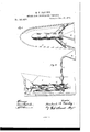
Be it known that I, HERBERT F. PARDEY, of the city of Chicago, Cook county, State of Illinois, have invented new and useful Improvements in Devices for Propelling Boats, of which the following is a full description, reference being bad to the accompanying drawings, in which Figure l is a plan view; Fig. 2, a vertical longitudinal section.
This invention relates to the new and novel devices used in propelling boats; and consists in the construction and combination of parts, which will be hereinafter more fully de-.
scribed, and pointed out by the claims.
In the drawings, A represents a portion of the hull of a boat. B is a chamber, located within the hull, at the stern of the boat, and sufficiently below the water-line. This chamber B is open at its outer end, but closed at the other end. 0 C are two tubes or passages, extending one from each side of the chamber B to an opening in the side of the boat. D is a shaft, supported in'suitable bearings. E is a continuous spiral wing, properly secured to the shaft D, forming a screw. F is an enlarged extension of the wing E, located upon that portion of the shaft D which is outside of the chamber B. a are valves, one in each tube 0. G is a funnel, from which extends a tube, 1), the lower end of which opens into the chamber B at its inner end. Between the funnel and the chamber B is a small air-chamber, c, and the tube which passes from c to the chamber B is considerably smaller than the tube b.
In use, the shaft D is to be rotated by any suitable means. By the action of the screw E the water in the chamber B will be thrown out therefrom with more or less force, depending upon the speed with which it revolves, giving forward motion to the boat, which motion will be accelerated by the action of the enlargement F in the water at the rear of the boat. Water to supply the place of that thrown from the chamber B by the screw E will flow in through the tubes 0, keeping the chamberB filled. The movement of the screw is in comparatively still water, and there is no large body of water in the chamber B.
By closing one of the valves a, water will be excluded from one side of the chamber B, which exclusion will aid in steering the boat. I have not shown the devices for operating these valves; but any suitable devices may be used for that purpose. These valves a are not designed to take the place of the ordinary rudder, which must be used, though if the rudder should be disabled the boat could be steered by the use of the valves.
Under ordinary circumstances air will be caught by the funnel G, and a current will be forced down the tube b into the chamber 0, and theneeinto the chamber B, and the pressure of the air upon the water will aid in propelling the boat.
The openings in the sides of the boat are to be so formed as to facilitate the passage of ater into the tubes 0 G. i
The construction shown relieves the boat from considerable strain, and adds to its strength.
The enlargement F of the screw, and forming a part thereof, receives the water as it is forced from the chamber, which materially aids in the efficiency of propelling the boat, while the funnel G receives considerable air,
which, when ejected into the chamber with a the water, has the same efficiency and power as the water in assisting to propel the boat, while the standard 1? allows the shaft D to have a rear hearing at its rear end.
What I claim as new, and desire to secure by Letters Patent, is as follows:
1. The shaft D, provided with the screw or spiral wing E and the enlarged portion F, extending outside of the boat and chamber, substantially as and for the purpose set forth.
2. The chamber B and spiral wing E, in combination with the funnel G and tube b, leading into the chamber, substantially as and for the purpose set forth.
3. The funnel G and tube b, provided with air-chamber c, in combination with the chamber B and spiral wing E, substantially as and E. A. WEST, O. W. Bonn.
Publications (1)
| Publication Number | Publication Date |
|---|---|
| US185454A true US185454A (en) | 1876-12-19 |
Family
ID=2254860
Family Applications (1)
| Application Number | Title | Priority Date | Filing Date |
|---|---|---|---|
| US185454D Expired - Lifetime US185454A (en) | Improvement in means for propelling vessels |
Country Status (1)
| Country | Link |
|---|---|
| US (1) | US185454A (en) |
Cited By (2)
| Publication number | Priority date | Publication date | Assignee | Title |
|---|---|---|---|---|
| US5679037A (en) * | 1996-03-01 | 1997-10-21 | Rieben; Leo R. | Stationary screw induction system |
| US20060065584A1 (en) * | 2004-03-05 | 2006-03-30 | Donaldson Company, Inc. | Liquid filter assembly for use with treatment agent and methods |
-
0
- US US185454D patent/US185454A/en not_active Expired - Lifetime
Cited By (2)
| Publication number | Priority date | Publication date | Assignee | Title |
|---|---|---|---|---|
| US5679037A (en) * | 1996-03-01 | 1997-10-21 | Rieben; Leo R. | Stationary screw induction system |
| US20060065584A1 (en) * | 2004-03-05 | 2006-03-30 | Donaldson Company, Inc. | Liquid filter assembly for use with treatment agent and methods |
Similar Documents
| Publication | Publication Date | Title |
|---|---|---|
| FI109014B (en) | Traction system for chassis | |
| JPS6127237B2 (en) | ||
| US185454A (en) | Improvement in means for propelling vessels | |
| US2467022A (en) | Marine propulsion and steering device | |
| US442615A (en) | Marine propulsion | |
| US1470191A (en) | Ship-propulsion apparatus | |
| US512591A (en) | Hydraulic propulsion of vessels | |
| US855165A (en) | Device for propelling and steering vessels. | |
| US671089A (en) | Hydraulic propeller. | |
| US1265309A (en) | Propelling mechanism for vessels. | |
| US451086A (en) | Propeller for vessels | |
| US441965A (en) | Propulsion of vessels | |
| US471274A (en) | Screw-propulsion of vessels | |
| US1256246A (en) | Boat. | |
| US955214A (en) | Propulsion of vessels. | |
| US1548936A (en) | Means for propelling boats | |
| US464898A (en) | Screw propeller | |
| US2233231A (en) | Boat propeller | |
| US961306A (en) | Apparatus for the propulsion of ships. | |
| US829033A (en) | Means for vessel propulsion. | |
| US253215A (en) | Alfeed maynaed | |
| US175436A (en) | Improvement in propelling canal-boats | |
| US565021A (en) | Propeller for vessels | |
| US624271A (en) | Pneumatic propulsion means | |
| US1288106A (en) | Steering mechanism for vessels. |