US1854477A - Tubing bleeder - Google Patents
Tubing bleeder Download PDFInfo
- Publication number
- US1854477A US1854477A US393800A US39380029A US1854477A US 1854477 A US1854477 A US 1854477A US 393800 A US393800 A US 393800A US 39380029 A US39380029 A US 39380029A US 1854477 A US1854477 A US 1854477A
- Authority
- US
- United States
- Prior art keywords
- plug
- tubing
- nipple
- bore
- frangible
- Prior art date
- Legal status (The legal status is an assumption and is not a legal conclusion. Google has not performed a legal analysis and makes no representation as to the accuracy of the status listed.)
- Expired - Lifetime
Links
- 210000002445 nipple Anatomy 0.000 description 16
- 239000007788 liquid Substances 0.000 description 3
- 230000000740 bleeding effect Effects 0.000 description 2
- 239000012530 fluid Substances 0.000 description 2
- 241000364021 Tulsa Species 0.000 description 1
- 230000004075 alteration Effects 0.000 description 1
- 238000010276 construction Methods 0.000 description 1
- 230000004048 modification Effects 0.000 description 1
- 238000012986 modification Methods 0.000 description 1
Images

Classifications
-
- E—FIXED CONSTRUCTIONS
- E21—EARTH DRILLING; MINING
- E21B—EARTH DRILLING, e.g. DEEP DRILLING; OBTAINING OIL, GAS, WATER, SOLUBLE OR MELTABLE MATERIALS OR A SLURRY OF MINERALS FROM WELLS
- E21B34/00—Valve arrangements for boreholes or wells
- E21B34/06—Valve arrangements for boreholes or wells in wells
- E21B34/063—Valve or closure with destructible element, e.g. frangible disc
-
- Y—GENERAL TAGGING OF NEW TECHNOLOGICAL DEVELOPMENTS; GENERAL TAGGING OF CROSS-SECTIONAL TECHNOLOGIES SPANNING OVER SEVERAL SECTIONS OF THE IPC; TECHNICAL SUBJECTS COVERED BY FORMER USPC CROSS-REFERENCE ART COLLECTIONS [XRACs] AND DIGESTS
- Y10—TECHNICAL SUBJECTS COVERED BY FORMER USPC
- Y10T—TECHNICAL SUBJECTS COVERED BY FORMER US CLASSIFICATION
- Y10T137/00—Fluid handling
- Y10T137/1624—Destructible or deformable element controlled
- Y10T137/1632—Destructible element
- Y10T137/1669—Tensile or sheer pin or bolt
Definitions
- This invention relates to new and useful improvements in tubing bleeders for wells.
- One object of the invention is to-provide frangible means in the tubing assembly so exposed in the bore or fluid passage of the tubing assembly as to be in the. path of a weight dropped in the tubing, whereby the frangible element will be fractured andthe liquid standing in the tubing above the element will be drained out.
- a further object of the invention is to provide a frangible plug arranged to be screwed into the wall of the tubing assembly so as to protrude into the bore thereof and having a sealed duct to be opened when the protruding portion of the plug is fractured by a weight dropped in the tubing.
- Another object of the invention is to provide a nipple for connecting in the tubing assembly preferably below the working valve, but above the standing valve and provided with a frangible element exposed in the bore for bleeding the tubing assembly when broken.
- a still further object of the invention is to h provide a frangible plug having a sealed duct and provided with screw threads so that it may be screwed into the side wall of the nipple or tubing assembly and readily replaced when broken.
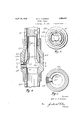
- Fig. 1 is a vertical sectional view of a portion of a working barrel including bleeding means constructed in accordance with the invention.
- Fig. 2 is a plan view of the same.
- Fig. 3 is a horizontal cross-sectional view taken on the line 3-3 of Fig. 1.
- Fig. 4 is a view similar to Fig. 1 showing another form of the invention.
- Fig. 5 is a plan view of the same.
- Fig. 6 is a horizontal cross-sectional view taken on the line 6-6 of Fig. 4.
- the numeral 10 designates a section of working barrel having a nipple 11 coupled therein, b-y collars 12 and 13, intermediate the working valve and the standing valve, preferably nearer the standing valve.
- the nipple has a reduced inside diameter or bore 14 with a flared throat 15 thereto at its upper end serving as a guide for a weight dropped therein.
- a screw threaded opening 16 is provided in the side of the nipple and has screwed therein a headed frangible plug 18 having a sealed passage or duct 19.
- the sealed end of said plug extends into the reduced bore in the path of a weight dropped therein; whereby the plug will be fractured allowing for the drainage of liquid standing in the tubing above said plug.
- the nipple being of reduced bore eliminatcs the possibility of the working valve entering said nipple and fracturing the plug when said valve is in operation.
- FIG. 4 Another form of the invention for use above the working barrel, as shown in Figures 4, 5, and 6, has a nipple so coupled intermediate a section of tubing 21 and a Working barrel 22.
- the nipple has a shoulder 23 providing for an enlarged bore 24 within said nipple.
- the enlarged bore is flared at its upper end 25 from the bore of the tubing and terminates at its lower end in a shelf 26, a frangible plug 27 having a sealed passage or duct 28 is screwed in an opening 29 of the nipple, said opening being located near the bottom of the enlarged bore.
- the plug is headless but is provided with a suitable tool seat for screwing it into said opening thereby allowing said plug to be flush with the face of the shoulder.
- the sealed end of the plug extends into the enlarged bore within the limits of the shelf 26 thus out of the path of the working valve but within the path of a suitable weight 30 adapted to be dropped therein,thereby eliminating the possibility of the accidental fracture of said plug.
- the suitable weight 30 to be dro ped for fracturing the plug is yoke shape having 100 spring arms 31 terminating in shoes 32,
- This weight is of suflicient weight to overcome the'friction of the spring arms against the sides of the tubing and to provide suflicient force to fracture the plug when dropped thereon.
- the arms of the weight will expand into the enlarged bore of the nipple allowing the curved breaking edges of the shoes to make contact with the plug, whereby said plug will be fractured allowing for the drainage of liquid standing in the tubing above the plug.
- a tubing bleeder a tubing member having an opening in its side, and a frangible plug closing said opening and protruding into the member, said plug having a passage extending through the plug, the inner end of the passage being closed.
- a tubing bleeder a tubing member having an opening in its side, and a frangible plug closing said opening, said plug having a a discharge passage closed at its inner end and arranged to be opened upon fracture of the plug to drain the tubing.
- a tubing nipple having a bore less in diameter than the tubing to which it is coupled, said nipple having a removable frangible plug screwed into one side and protruding into the bore of said nipple, said plug having a passage therein sealed at its inner end.
- a pump for wells having a fluid passageway upwardly therethrough and a frangible plug threaded through the pump wall with its inner end projecting into said passageway, the outer end of the plug having a socket located so as to form a drain outlet when the inner end of the plug is broken off.
Description
April 19, 1932.
W. H. M KISSICK TUBING BLEEDER Filed 2 Sheets-Sheet 1 Sept. 19, 1929 Patented Apr. 19, 1932 UNITED STATES WILLIAM H. MCKISSICK, OF TULSA, OKLAHOMA TUBING BLEEDER Application filed September 19, 1929. Serial No. 393,800.
This invention relates to new and useful improvements in tubing bleeders for wells.
One object of the invention is to-provide frangible means in the tubing assembly so exposed in the bore or fluid passage of the tubing assembly as to be in the. path of a weight dropped in the tubing, whereby the frangible element will be fractured andthe liquid standing in the tubing above the element will be drained out.
A further object of the invention is to provide a frangible plug arranged to be screwed into the wall of the tubing assembly so as to protrude into the bore thereof and having a sealed duct to be opened when the protruding portion of the plug is fractured by a weight dropped in the tubing.
Another object of the invention is to provide a nipple for connecting in the tubing assembly preferably below the working valve, but above the standing valve and provided with a frangible element exposed in the bore for bleeding the tubing assembly when broken.
A still further object of the invention is to h provide a frangible plug having a sealed duct and provided with screw threads so that it may be screwed into the side wall of the nipple or tubing assembly and readily replaced when broken.
A construction designed to carry out the invention will be hereinafter described together with other features of the invention.
The invention will be more readily understood from a reading of the following specification and by reference to the accompanying drawings in which an example of the invention is shown, and wherein Fig. 1 is a vertical sectional view of a portion of a working barrel including bleeding means constructed in accordance with the invention.
Fig. 2 is a plan view of the same.
Fig. 3 is a horizontal cross-sectional view taken on the line 3-3 of Fig. 1.
Fig. 4 is a view similar to Fig. 1 showing another form of the invention.
Fig. 5 is a plan view of the same, and
Fig. 6 is a horizontal cross-sectional view taken on the line 6-6 of Fig. 4.
In the drawings the numeral 10 designates a section of working barrel having a nipple 11 coupled therein, b-y collars 12 and 13, intermediate the working valve and the standing valve, preferably nearer the standing valve.
The nipple has a reduced inside diameter or bore 14 with a flared throat 15 thereto at its upper end serving as a guide for a weight dropped therein.
A screw threaded opening 16 is provided in the side of the nipple and has screwed therein a headed frangible plug 18 having a sealed passage or duct 19. The sealed end of said plug extends into the reduced bore in the path of a weight dropped therein; whereby the plug will be fractured allowing for the drainage of liquid standing in the tubing above said plug.
The nipple being of reduced bore eliminatcs the possibility of the working valve entering said nipple and fracturing the plug when said valve is in operation.
Another form of the invention for use above the working barrel, as shown in Figures 4, 5, and 6, has a nipple so coupled intermediate a section of tubing 21 and a Working barrel 22.
The nipple has a shoulder 23 providing for an enlarged bore 24 within said nipple. The enlarged bore is flared at its upper end 25 from the bore of the tubing and terminates at its lower end in a shelf 26, a frangible plug 27 having a sealed passage or duct 28 is screwed in an opening 29 of the nipple, said opening being located near the bottom of the enlarged bore.
The plug is headless but is provided with a suitable tool seat for screwing it into said opening thereby allowing said plug to be flush with the face of the shoulder. The sealed end of the plug extends into the enlarged bore within the limits of the shelf 26 thus out of the path of the working valve but within the path of a suitable weight 30 adapted to be dropped therein,thereby eliminating the possibility of the accidental fracture of said plug.
The suitable weight 30 to be dro ped for fracturing the plug is yoke shape having 100 spring arms 31 terminating in shoes 32,
enlarged to conform with the enlarged bore of said nipple and having a curved breaking edge 33. This weight is of suflicient weight to overcome the'friction of the spring arms against the sides of the tubing and to provide suflicient force to fracture the plug when dropped thereon. The arms of the weight will expand into the enlarged bore of the nipple allowing the curved breaking edges of the shoes to make contact with the plug, whereby said plug will be fractured allowing for the drainage of liquid standing in the tubing above the plug.
Various changes in the size and shape of the different parts, as well as modifications and alterations, may be made within the scope of the appended claims.
What I claim is:
1. In a tubing bleeder, a tubing member having an opening in its side, and a frangible plug closing said opening and protruding into the member, said plug having a passage extending through the plug, the inner end of the passage being closed.
2. In a tubing bleeder, a tubing member having an opening in its side, and a frangible plug closing said opening, said plug having a a discharge passage closed at its inner end and arranged to be opened upon fracture of the plug to drain the tubing.
3. In a tubing bleeder, a tubing nipple having a bore less in diameter than the tubing to which it is coupled, said nipple having a removable frangible plug screwed into one side and protruding into the bore of said nipple, said plug having a passage therein sealed at its inner end.
4. A pump for wells having a fluid passageway upwardly therethrough and a frangible plug threaded through the pump wall with its inner end projecting into said passageway, the outer end of the plug having a socket located so as to form a drain outlet when the inner end of the plug is broken off.
In testimony whereof I aflix my signature.
WILLIAM H. MCKISSICK.
Priority Applications (1)
| Application Number | Priority Date | Filing Date | Title |
|---|---|---|---|
| US393800A US1854477A (en) | 1929-09-19 | 1929-09-19 | Tubing bleeder |
Applications Claiming Priority (1)
| Application Number | Priority Date | Filing Date | Title |
|---|---|---|---|
| US393800A US1854477A (en) | 1929-09-19 | 1929-09-19 | Tubing bleeder |
Publications (1)
| Publication Number | Publication Date |
|---|---|
| US1854477A true US1854477A (en) | 1932-04-19 |
Family
ID=23556299
Family Applications (1)
| Application Number | Title | Priority Date | Filing Date |
|---|---|---|---|
| US393800A Expired - Lifetime US1854477A (en) | 1929-09-19 | 1929-09-19 | Tubing bleeder |
Country Status (1)
| Country | Link |
|---|---|
| US (1) | US1854477A (en) |
Cited By (17)
| Publication number | Priority date | Publication date | Assignee | Title |
|---|---|---|---|---|
| US2855943A (en) * | 1956-03-20 | 1958-10-14 | Bynum W Moller | Circulation port assemblies for tubing or well pipe |
| US2885008A (en) * | 1954-09-07 | 1959-05-05 | Temple P Hoffer | Flow directing device |
| US2922479A (en) * | 1956-05-28 | 1960-01-26 | Kinley Myron Macy | Apparatus for controlling fluid circulation |
| US2937654A (en) * | 1958-02-10 | 1960-05-24 | Wilner L Bruce | Tube shearing valve |
| US3093151A (en) * | 1958-09-12 | 1963-06-11 | Gen Dynamics Corp | Shear valve and frangible fitting |
| US3095040A (en) * | 1961-06-30 | 1963-06-25 | Bramlett Oil Field Service Inc | Access valve for completing oil wells |
| US3111133A (en) * | 1959-08-11 | 1963-11-19 | Hydro Space Technology Inc | Explosive actuated normally closed valve |
| US3670914A (en) * | 1970-05-21 | 1972-06-20 | Airco Inc | Break seal |
| FR2581699A1 (en) * | 1985-05-13 | 1986-11-14 | Inst Francais Du Petrole | ROD TRAIN EQUIPMENT, SUCH AS A DRILL ROD TRAIN, COMPRISING A LATERAL WINDOW CONNECTION FOR PASSING A CABLE |
| US4673039A (en) * | 1986-01-24 | 1987-06-16 | Mohaupt Henry H | Well completion technique |
| US4944351A (en) * | 1989-10-26 | 1990-07-31 | Baker Hughes Incorporated | Downhole safety valve for subterranean well and method |
| US5305914A (en) * | 1993-03-23 | 1994-04-26 | Cartridge Actuated Devices, Inc. | Pressurized gas bottle discharge device |
| US5782305A (en) * | 1996-11-18 | 1998-07-21 | Texaco Inc. | Method and apparatus for removing fluid from production tubing into the well |
| US6591915B2 (en) * | 1998-05-14 | 2003-07-15 | Fike Corporation | Method for selective draining of liquid from an oil well pipe string |
| CN105443060A (en) * | 2016-01-06 | 2016-03-30 | 东营市海天石油科技有限责任公司 | Oil pipe drainage anchor |
| US10030472B2 (en) | 2014-02-25 | 2018-07-24 | Halliburton Energy Services, Inc. | Frangible plug to control flow through a completion |
| US10145482B2 (en) | 2014-01-29 | 2018-12-04 | Raytheon Company | Frangible valve |
-
1929
- 1929-09-19 US US393800A patent/US1854477A/en not_active Expired - Lifetime
Cited By (21)
| Publication number | Priority date | Publication date | Assignee | Title |
|---|---|---|---|---|
| US2885008A (en) * | 1954-09-07 | 1959-05-05 | Temple P Hoffer | Flow directing device |
| US2855943A (en) * | 1956-03-20 | 1958-10-14 | Bynum W Moller | Circulation port assemblies for tubing or well pipe |
| US2922479A (en) * | 1956-05-28 | 1960-01-26 | Kinley Myron Macy | Apparatus for controlling fluid circulation |
| US2937654A (en) * | 1958-02-10 | 1960-05-24 | Wilner L Bruce | Tube shearing valve |
| US3093151A (en) * | 1958-09-12 | 1963-06-11 | Gen Dynamics Corp | Shear valve and frangible fitting |
| US3111133A (en) * | 1959-08-11 | 1963-11-19 | Hydro Space Technology Inc | Explosive actuated normally closed valve |
| US3095040A (en) * | 1961-06-30 | 1963-06-25 | Bramlett Oil Field Service Inc | Access valve for completing oil wells |
| US3670914A (en) * | 1970-05-21 | 1972-06-20 | Airco Inc | Break seal |
| FR2581699A1 (en) * | 1985-05-13 | 1986-11-14 | Inst Francais Du Petrole | ROD TRAIN EQUIPMENT, SUCH AS A DRILL ROD TRAIN, COMPRISING A LATERAL WINDOW CONNECTION FOR PASSING A CABLE |
| EP0202151A1 (en) * | 1985-05-13 | 1986-11-20 | Institut Français du Pétrole | Apparatus for a drill pipe or the like, comprising a side entry SUB for a cable |
| US4673039A (en) * | 1986-01-24 | 1987-06-16 | Mohaupt Henry H | Well completion technique |
| US4944351A (en) * | 1989-10-26 | 1990-07-31 | Baker Hughes Incorporated | Downhole safety valve for subterranean well and method |
| US5305914A (en) * | 1993-03-23 | 1994-04-26 | Cartridge Actuated Devices, Inc. | Pressurized gas bottle discharge device |
| US5782305A (en) * | 1996-11-18 | 1998-07-21 | Texaco Inc. | Method and apparatus for removing fluid from production tubing into the well |
| US6591915B2 (en) * | 1998-05-14 | 2003-07-15 | Fike Corporation | Method for selective draining of liquid from an oil well pipe string |
| US20030192701A1 (en) * | 1998-05-14 | 2003-10-16 | Burris Mark A. | Dump valve assembly for selective draining of liquid from an oil well pipe stream |
| US6752212B2 (en) * | 1998-05-14 | 2004-06-22 | Fike Corporation | Dump valve assembly for selective draining of liquid from an oil well pipe stream |
| US20040216867A1 (en) * | 1998-05-14 | 2004-11-04 | Burris Mark A. | Dump hole dump valve |
| US10145482B2 (en) | 2014-01-29 | 2018-12-04 | Raytheon Company | Frangible valve |
| US10030472B2 (en) | 2014-02-25 | 2018-07-24 | Halliburton Energy Services, Inc. | Frangible plug to control flow through a completion |
| CN105443060A (en) * | 2016-01-06 | 2016-03-30 | 东营市海天石油科技有限责任公司 | Oil pipe drainage anchor |
Similar Documents
| Publication | Publication Date | Title |
|---|---|---|
| US1854477A (en) | Tubing bleeder | |
| US2092261A (en) | Tubing head for wells | |
| US1890223A (en) | Drill pipe float coupling | |
| US2349164A (en) | Bottom hole intermitter for pumping wells | |
| US2154811A (en) | Primer valve | |
| US1601676A (en) | Tubing drain | |
| US1487061A (en) | Pump-cylinder protector | |
| US1493149A (en) | Double-valve construction | |
| US2363290A (en) | Improved bleeder valve | |
| GB2603365A (en) | Liner wiper plug with rupture disk for wet shoe | |
| US2070907A (en) | Tubing bleeder | |
| US1612857A (en) | Ball-cock valve | |
| US2231820A (en) | Pump | |
| US1717022A (en) | Combination stop and check valve | |
| US1519219A (en) | Jar for removing standing valves | |
| US1574292A (en) | Pump | |
| US2372191A (en) | Vacuum pump | |
| US1552870A (en) | Pump valve | |
| US1756499A (en) | Tubing drain | |
| US1993266A (en) | Plunger lift device | |
| US1947587A (en) | Plunger lift valve closing device | |
| US2215916A (en) | Overhead tank valve | |
| US2079140A (en) | Formation tester | |
| US2398305A (en) | Valve puller | |
| US2272022A (en) | Tubing head |