US1854468A - Refrigerating cabinet - Google Patents
Refrigerating cabinet Download PDFInfo
- Publication number
- US1854468A US1854468A US126903A US12690326A US1854468A US 1854468 A US1854468 A US 1854468A US 126903 A US126903 A US 126903A US 12690326 A US12690326 A US 12690326A US 1854468 A US1854468 A US 1854468A
- Authority
- US
- United States
- Prior art keywords
- cabinet
- refrigerant
- chamber
- space
- pipe
- Prior art date
- Legal status (The legal status is an assumption and is not a legal conclusion. Google has not performed a legal analysis and makes no representation as to the accuracy of the status listed.)
- Expired - Lifetime
Links
Images

Classifications
-
- A—HUMAN NECESSITIES
- A47—FURNITURE; DOMESTIC ARTICLES OR APPLIANCES; COFFEE MILLS; SPICE MILLS; SUCTION CLEANERS IN GENERAL
- A47F—SPECIAL FURNITURE, FITTINGS, OR ACCESSORIES FOR SHOPS, STOREHOUSES, BARS, RESTAURANTS OR THE LIKE; PAYING COUNTERS
- A47F3/00—Show cases or show cabinets
- A47F3/04—Show cases or show cabinets air-conditioned, refrigerated
- A47F3/0404—Cases or cabinets of the closed type
- A47F3/0417—Cases or cabinets of the closed type with natural air circulation
Definitions
- This invention relates to refrigeration and cooling, and especially to a system adapted to cabinets usually involvesthe passage of a' cold refrigerant through a series of convolution's, placed in the interior of the cabinet in v such a way that a substantially uniform low temperature is obtained in all parts of the cabinet.
- the cooling effect is secured in the same manner as in the usual refrigerating system; for example, a refrigerant such as su1 phur dioxide, can be caused to pass through the usual cycle of expansion and evaporation with attendent absorption of heat, in an expansionspace, usually in the form of a series of convolutions. It has been attempted in prior systems to provide uniform low temperatures in the vcabinet by proper distribution of the convolutions; but this is sometimes inconvenient, nor is it always thoroughly efficacious.
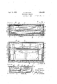
- Fi re 1 is a horizontal sectional View, of a cab1 et incorporating my invention, the section being taken substantially along plane 11 of Fig. 3, but with certain parts omitted for clarity; I r
- Fig. 2 is a longitudinal vertical section, of the cabinet shown in Fig. 1
- Fig. 3 is a sectional view, taken along plane 33 of Fig. 1;
- Fig. 4 is a diagram showing how my invention can be adapted to larger size spaces or cabinets.
- examplefl'the cabinet ingeneral can. have exterior walls 11 of wood, as well as a bottom 12 of wood.
- a hefivy cork lining 13 can be used if desired.
- a rim or band 14 extezgs completely around the cabinet and over e lining of insulation 13.
- Sheet metal flashing 15 covers the layer .13 and provides in addi-' tion a water tight lining.
- v v The rim 14 serves to support the glass front structure, which consists in this instance of two spaced sloping glass walls 16 and 17. These plates 16 and 17 rest upon the band 14, and can be held in place thereat by molding 18.
- the top of the cabinet can also be formed of double glass plates 19 and 20.
- the cabinet is of the and that can be used to display meat or other foods.
- Trays 27 of Wire or the like can rest on the shoulders'28 formed above the cork insulation 13 and by the aid of the band14. Upon these trays the "food on display can rest. A slight distance below the trays, a
- pan 29 of sheet metal is provided to catch drippings; the rear and sides being supported by the aidof upturned flanges 30, upon the rear and side walls of the cabinet.
- the front edge is also flanged, as indicated at 31, Fig. 3,
- a plurality of brackets 32 serve to support this front edge.
- the pan 29 slopes to the rear in order to drain the moisture; and a drain pipe 33 serves to drain this moisture from the pan.
- the refrigerant in a liquid state is supplied to the various expansion spaces inside of the cabinet, through a pipe 34; and it returns in a gaseous state from the cabinet through a pipe 35. Both these pipes extend below the pan 29.
- the liquid refrigerant passes through pipe 34 into a container or chamber 36, the details of which are disclosed most clearly in Fig. 3.
- This chamber presents a large and sudden increase in the area of the space through which the refrigerant must pass, and therefore rapid evaporation with cooling, results.
- Such a chamber is described and claimed in a pending application filed May 10, 1926, in my name, entitled Refrigcrating system and having Serial. Number 109,306. It is in the form of a double walled container, in the present instance cylindrical, between the walls of which the refrigerant is conducted. 7
- the chamber 36 is chown, inthis instance as made from an inner and outer cylinder to which the apertured ends 37 are welded toform a closed container.
- the inner cylinder forms a flue for the passage of air, which is cooled by contact with thechamber and settles close to the bottom of the cabinet.
- the chamber 36 rests on legs or supports 38 fastened to the bottom of the cabinet, but which do not impede the flow of convection currents in the chamber.
- the provision of a flue-like container is of considerable importance. I t initiates an efficient movement of cold air in the cabinet and provides a uniform degree of cold therein.
- the pipe leads into the chamber 36 at or below the normal liquid line therein-
- the outlet pipe has an upwardly extending portion 39 (Fig. 3) connecting near the top of the chamber 36, well above the liquid level therein.
- - I preferably provide another expansion chamber 40 of the same structure as chamber 36, but at the other end of the cabinet.
- pan 29 is cut around these tanks, and has depending portions 41 defining a square space with the corners of the cabinet to accommodate these chambers.
- the conduit 42 connects -to both tanks 36 and 40 below the liquid level, whereby the transfer of cold refrigerant through the conduit is effected.
- the expanded gaseous refrigerant in tank 40 passes through a conduit 43 into pipe 35 leading to the compressor. This conduit 43 connects to tank 40 adjacent the top thereof.
- the system produces rapid convection currents of cooling air; and in addition a large cooling surface, formed by conduit 42, is effective to equalize the temperature.
- a large cooling surface formed by conduit 42, is effective to equalize the temperature.
- the large cabinet 44 has three tanks 45, 46 and 47.
- the center tank 46 is connected to the outlet of a compressor, as by pipe 48, whereby refrigerant in a liquid state is supplied to the systerm.
- the other chambers 45 and 47 are each connected to chamber 46 through convoluted conduits 49 and 50, similar to conduit 42, and arranged near the liquid level in the chambers.
- a common return pipe 51 connects to the vapor space in all three chambers.
- a refrigerator means forming a space to be cooled, a plurality of containers in said space, means for leading refrigerant to one of said containers, means for conducting refrigerant away from all of said containers, and means whereby refrigerant is distributed from said one container to the others, com prising a convoluted conduit.
- a refrigerator means forming a space to be cooled, a pair of cylindrical, vertically arranged, double-walled containers in to be cooled, a palr of closed contamers, one
- each end of the space having an open flue extending substantially vertically therethrough, and connections between the containers for providing a circulatory sipace for the refrigerant.
- n combination means forming a space 'to be cooled, a plurality of closed double walled containers in said space, each container having a clear upright flue therethrough,
Description
Patented Apr. 159, 1932 UNITED STATES I PATENT OFFICE 'WILFRED FOURNESS, 0]! PASADENA, CALIFORNIA,ASSIGNOR BY MESNE ASSIGNMENTS,
TO FOURNESS DEVELOPMENT CORPORATION LTD., OF NEW YORK, N. Y., A CORPORA- TION OF NEW YORK REFBIGERATING CABINET Application filed August 3, 1926. Serial No. 126,908.
This invention relates to refrigeration and cooling, and especially to a system adapted to cabinets usually involvesthe passage of a' cold refrigerant through a series of convolution's, placed in the interior of the cabinet in v such a way that a substantially uniform low temperature is obtained in all parts of the cabinet. The cooling effect is secured in the same manner as in the usual refrigerating system; for example, a refrigerant such as su1 phur dioxide, can be caused to pass through the usual cycle of expansion and evaporation with attendent absorption of heat, in an expansionspace, usually in the form of a series of convolutions. It has been attempted in prior systems to provide uniform low temperatures in the vcabinet by proper distribution of the convolutions; but this is sometimes inconvenient, nor is it always thoroughly efficacious.
It is one of the objects of my invention to secure substantial uniformity of temperature in a simple and inexpensive manner.
It is another object of my invention to provide this uniformity by setting up a movement of the air in convection currents, in the V space to be cooled.
It is still another object of my invention to make it possible to fit the system to any sized space to be cooled, by providing additional units of equipment.
' My invention possesses many other advantages, and has other objects which may be made more easily apparent from a consideration of one embodiment of my invention. For this purpose I have shown a form in the drawings accompanyin-g and formingpart of the present specification. I shall now proceed to describe this form in detail, which illustrates the general principles of my invention; but it is to be understood that this detailed description'is not to be taken in a limiting sense, since the scope of my invention is best defined by the appended claims.
Referring to the drawings:
Fi re 1 is a horizontal sectional View, of a cab1 et incorporating my invention, the section being taken substantially along plane 11 of Fig. 3, but with certain parts omitted for clarity; I r
Fig. 2 is a longitudinal vertical section, of the cabinet shown in Fig. 1
Fig. 3 is a sectional view, taken along plane 33 of Fig. 1; and
Fig. 4 is a diagram showing how my invention can be adapted to larger size spaces or cabinets.
In the present instance I show my invention applied to a store cabinet, having an interior space well insulated against heat. For
examplefl'the cabinet ingeneral can. have exterior walls 11 of wood, as well as a bottom 12 of wood. A hefivy cork lining 13 can be used if desired. A rim or band 14 extezgs completely around the cabinet and over e lining of insulation 13. Sheet metal flashing 15 covers the layer .13 and provides in addi-' tion a water tight lining. v v The rim 14 serves to support the glass front structure, which consists in this instance of two spaced sloping glass walls 16 and 17. These plates 16 and 17 rest upon the band 14, and can be held in place thereat by molding 18. The top of the cabinet can also be formed of double glass plates 19 and 20. The rear edges of these plates are fastened to the rear wall 11 and a lining 21 of wood which extends above band 14. Molding 22 across this lining 21 servesas a rest for the bottom plate 20. Both plates 19 and 20 are cemented or otherwise fastened adjacent their front edges to plates 16 and 17.; and 'a molding 23 can be "up of insulation and flashing linings in a manner similar to the walls of the cabinet.
As thus far described, the cabinet is of the and that can be used to display meat or other foods. Trays 27 of Wire or the like can rest on the shoulders'28 formed above the cork insulation 13 and by the aid of the band14. Upon these trays the "food on display can rest. A slight distance below the trays, a
but is spaced from the front of the cabinet to permit air circulation between the upper and lower portions of the cabinet. A plurality of brackets 32 serve to support this front edge. The pan 29 slopes to the rear in order to drain the moisture; and a drain pipe 33 serves to drain this moisture from the pan.
The refrigerant in a liquid state is supplied to the various expansion spaces inside of the cabinet, through a pipe 34; and it returns in a gaseous state from the cabinet through a pipe 35. Both these pipes extend below the pan 29. The liquid refrigerant passes through pipe 34 into a container or chamber 36, the details of which are disclosed most clearly in Fig. 3. This chamber presents a large and sudden increase in the area of the space through which the refrigerant must pass, and therefore rapid evaporation with cooling, results. Such a chamber is described and claimed in a pending application filed May 10, 1926, in my name, entitled Refrigcrating system and having Serial. Number 109,306. It is in the form of a double walled container, in the present instance cylindrical, between the walls of which the refrigerant is conducted. 7
Y The chamber 36 is chown, inthis instance as made from an inner and outer cylinder to which the apertured ends 37 are welded toform a closed container. By placing the chamber 36 inan upright position, it is seen that the inner cylinder forms a flue for the passage of air, which is cooled by contact with thechamber and settles close to the bottom of the cabinet. The chamber 36 rests on legs or supports 38 fastened to the bottom of the cabinet, but which do not impede the flow of convection currents in the chamber. The provision of a flue-like container is of considerable importance. I t initiates an efficient movement of cold air in the cabinet and provides a uniform degree of cold therein.
The pipe leads into the chamber 36 at or below the normal liquid line therein- The outlet pipe has an upwardly extending portion 39 (Fig. 3) connecting near the top of the chamber 36, well above the liquid level therein.
- I preferably provide another expansion chamber 40 of the same structure as chamber 36, but at the other end of the cabinet. The
I conduct refrigerant from chamber 36 into chamber 40 through a pipe or conduit 42 in the form of a series of convolutions, disposed immediately below the trays 27. These convolutions also assist in cooling the interior of the cabinet, and thus serve a double function. The conduit 42 connects -to both tanks 36 and 40 below the liquid level, whereby the transfer of cold refrigerant through the conduit is effected. The expanded gaseous refrigerant in tank 40 passes through a conduit 43 into pipe 35 leading to the compressor. This conduit 43 connects to tank 40 adjacent the top thereof.
It is evident that the system produces rapid convection currents of cooling air; and in addition a large cooling surface, formed by conduit 42, is effective to equalize the temperature. It is to be noted that but one of the chambers 36, 40, is in direct connection with the refrigerant supply; the other chamw capacity. Such a system is shown diagrammatically in Fig. 4. In this case, the large cabinet 44 has three tanks 45, 46 and 47. The center tank 46 is connected to the outlet of a compressor, as by pipe 48, whereby refrigerant in a liquid state is supplied to the systerm. The other chambers 45 and 47 are each connected to chamber 46 through convoluted conduits 49 and 50, similar to conduit 42, and arranged near the liquid level in the chambers. A common return pipe 51 connects to the vapor space in all three chambers.
' It is evident that. this arrangement can be further multiplied by the addition of further containers and convoluted pipes.
I claim:
1. In a refrigerator, means forming a space to be cooled, a plurality of containers in said space, means for leading refrigerant to one of said containers, means for conducting refrigerant away from all of said containers, and means whereby refrigerant is distributed from said one container to the others, com prising a convoluted conduit.
2. In a refrigerator, means forming a space to be cooled, a pair of cylindrical, vertically arranged, double-walled containers in to be cooled, a palr of closed contamers, one
adjacent each end of the space, and each having an open flue extending substantially vertically therethrough, and connections between the containers for providing a circulatory sipace for the refrigerant.
n combination, means forming a space 'to be cooled, a plurality of closed double walled containers in said space, each container having a clear upright flue therethrough,
, and having substantial volume so as to accommodate a refrigerant, and to permit it to ex and, and connections between the contamers forproviding a circulatory space for I the refri erant.
In testimony whereof I have hereunto "set; my hand.
WILFRED FOURNESS.
Priority Applications (1)
| Application Number | Priority Date | Filing Date | Title |
|---|---|---|---|
| US126903A US1854468A (en) | 1926-08-03 | 1926-08-03 | Refrigerating cabinet |
Applications Claiming Priority (1)
| Application Number | Priority Date | Filing Date | Title |
|---|---|---|---|
| US126903A US1854468A (en) | 1926-08-03 | 1926-08-03 | Refrigerating cabinet |
Publications (1)
| Publication Number | Publication Date |
|---|---|
| US1854468A true US1854468A (en) | 1932-04-19 |
Family
ID=22427296
Family Applications (1)
| Application Number | Title | Priority Date | Filing Date |
|---|---|---|---|
| US126903A Expired - Lifetime US1854468A (en) | 1926-08-03 | 1926-08-03 | Refrigerating cabinet |
Country Status (1)
| Country | Link |
|---|---|
| US (1) | US1854468A (en) |
Cited By (1)
| Publication number | Priority date | Publication date | Assignee | Title |
|---|---|---|---|---|
| US2484307A (en) * | 1944-07-10 | 1949-10-11 | Willard L Morrison | Nested cylinder cooler |
-
1926
- 1926-08-03 US US126903A patent/US1854468A/en not_active Expired - Lifetime
Cited By (1)
| Publication number | Priority date | Publication date | Assignee | Title |
|---|---|---|---|---|
| US2484307A (en) * | 1944-07-10 | 1949-10-11 | Willard L Morrison | Nested cylinder cooler |
Similar Documents
| Publication | Publication Date | Title |
|---|---|---|
| US2318532A (en) | Refrigerating system and apparatus | |
| US2261681A (en) | Refrigeration | |
| US1854468A (en) | Refrigerating cabinet | |
| US2375359A (en) | Refrigeration | |
| US1952148A (en) | Refrigerating apparatus | |
| US1825698A (en) | Refrigerating apparatus | |
| US1726344A (en) | Refrigerating apparatus | |
| US2047415A (en) | Refrigerator | |
| US2106263A (en) | Cooling cabinet | |
| US2946206A (en) | Refrigerator employing secondary refrigeration system | |
| US2509612A (en) | Refrigerating apparatus | |
| US2260825A (en) | Refrigerating apparatus | |
| US2215192A (en) | Cooler apparatus | |
| US1914300A (en) | Evaporator for refrigerators | |
| US2313499A (en) | Evaporator unit | |
| US2387840A (en) | Refrigerating apparatus | |
| US2022570A (en) | Ice safe | |
| US1918818A (en) | Refrigerating apparatus | |
| USRE18253E (en) | Befbigebatob and kefeioebatina ahpabatub | |
| US1829406A (en) | Refrigerating apparatus | |
| US1951223A (en) | Refrigerating apparatus | |
| US2878658A (en) | Freezing compartment for household refrigerator | |
| US1829407A (en) | Refrigerating apparatus | |
| US1827769A (en) | Refrigerating apparatus | |
| US2076770A (en) | Evaporator |