US185446A - Improvement in metallic car-platforms - Google Patents
Improvement in metallic car-platforms Download PDFInfo
- Publication number
- US185446A US185446A US185446DA US185446A US 185446 A US185446 A US 185446A US 185446D A US185446D A US 185446DA US 185446 A US185446 A US 185446A
- Authority
- US
- United States
- Prior art keywords
- tubes
- car
- metallic
- platform
- blocks
- Prior art date
- Legal status (The legal status is an assumption and is not a legal conclusion. Google has not performed a legal analysis and makes no representation as to the accuracy of the status listed.)
- Expired - Lifetime
Links
- 239000002184 metal Substances 0.000 description 12
- 229910052751 metal Inorganic materials 0.000 description 12
- 239000000203 mixture Substances 0.000 description 8
- 210000000614 Ribs Anatomy 0.000 description 6
- 230000000717 retained Effects 0.000 description 6
- 229910000754 Wrought iron Inorganic materials 0.000 description 4
- CWYNVVGOOAEACU-UHFFFAOYSA-N fe2+ Chemical compound [Fe+2] CWYNVVGOOAEACU-UHFFFAOYSA-N 0.000 description 4
- 229910000831 Steel Inorganic materials 0.000 description 2
- 150000001875 compounds Chemical class 0.000 description 2
- 238000007906 compression Methods 0.000 description 2
- 238000010276 construction Methods 0.000 description 2
- 230000001808 coupling Effects 0.000 description 2
- 238000010168 coupling process Methods 0.000 description 2
- 238000005859 coupling reaction Methods 0.000 description 2
- 238000009408 flooring Methods 0.000 description 2
- 239000000463 material Substances 0.000 description 2
- 239000010959 steel Substances 0.000 description 2
Images
Classifications
-
- B—PERFORMING OPERATIONS; TRANSPORTING
- B61—RAILWAYS
- B61D—BODY DETAILS OR KINDS OF RAILWAY VEHICLES
- B61D17/00—Construction details of vehicle bodies
- B61D17/04—Construction details of vehicle bodies with bodies of metal; with composite, e.g. metal and wood body structures
- B61D17/08—Sides
Definitions
- the present invention relates to a peculiar construction of intersection-block, whereby the number of tubes or bars running in one direction corresponds to the number running in the other direction, so as to obtain uniformity of strength transversely and longitudinally of the car, which is very essential in adapting the car to the various circumstances under which it is placed.
- 1 also employ intersection-blocks of varying lengths, in order that the tubes or rods may diverge or converge between one block and the next, and thereby there will be a slight bend produced at the intersectionblocks, in consequence of the holes in such blocks being par-. allel.
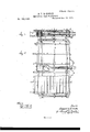
- Figure 1 is avertical crosssection of the car-frame.
- Fig. 2 is a plan below the line as m, and
- Fig. 3 is a section through the transom-beam.
- Fig. 4 is a section of the attaching-strap, and
- Fig. 5 is an elevation of the same.
- the tubes a pass longitudinally of the platform, and the tubes or bars I) b run transversely.
- the tubes 0 0 form the transombeam, between which tubes is the block d, that receives the king-bolt of the truck.
- Said block (I is retained by metallic bands wrapped aroundit and the adjacent tubes 0 c.
- the longitudinal and transverse tubes intersect each other, and they are tied together by means of metal straps e e, that are of flat strips of sheet metal wound into a coil of the proper size, and
- This mode of constructing the platform is preferable to that shown in my former Patent No. 105,699, because the wrought-iron bands hold the tubes or bars in direct contact one with the other, and allow for the introduction of larger tubes or a greater number of them, without increasing the thickness of the platform-frame.
- the tubes pass through the plate g, and are expanded so as to retain the plate firmly in position.
- the draft-bar h passes through this plate 9. It is provided with any suitable head or coupling between the buffer-blocks h, and the movement of the draft-bar is limited by the collars 2 and 3, so that the spring I: is not unduly strained in either direction.
- This spring k is a coil of steel wire of suitable size, and it is connected by a strap, 4, with the inner end of the draftbar, or by the end of the draft-bar forming such strap, and by a strap, 5, with the kingbolt block d, or the tubes 0 of the transombeam.
- a platform constructed as aforesaid can be used for a flat or platform car, or it can be provided with the upper portions next described, to form a box or passenger car.
- the vertical rods or tubes l are connected with the transverse tubes of the platform, and they are bent to give them the vertical position shown, and they pass through the intersection-blocks m, and these blocks m vary in length, as shown, so that the rods lconverge or diverge at the respective sides of such blocks, and hence bind in the parallel holes of the intersection-blocks, and lessen the risk of such blocks slipping or becoming displaced upon the said rods or tubes 1.
- the sheets of metal 0 are folded to form --thevertical ribs 8 8, that are double, and at a distance apart correspouding'tothe width metal bottom will prevent the leakage of grain or other material which may be in the car.
- the metallic car-platform made of longitudinal and transverse tubes or rods, secured together at the intersections by wroughtiron bands, in the manner specified. r r
- the band e for securing the tubes or rod a and b, made of a strip of sheet metal wound up and retained at its ends by the'band e, as V V V and for the purposes set forth. 3.
- the plate 9 at the end of the car-platby such tubes being passed through the said platerand spread, in combination with the transverse tubes b of'the platform, as set forth.
Description
Z Sheets-Sheet 1.
B. J. Le. MOTHE. METALLIC CAR PLATFORM.
Patented Dec. 19, 1876.
W W n m m fin w .u in
TH E GRAPH IC CONM ZSheets-Sheet 2.
: METALLIC CAR PLATFORM. No. 185,446. Patented Dec.19, 1876.
HE GRAPHIC CO.N.
UNITED STATES BERNARD J. LA MOTHE, OF NEW YORK, N. Y.
IMPROVEMENT IN METALLIC CAR-PLATFORMS.
I Specification forming part of Letters Patent No. 185,446, dated December 19, 1876; application filed October 11, 1875.
To all when it may concern:
Be it known that I, BERNARD J. LA MOTHE, of the city and State of New York, have invented an Improvement in Metallic Cars, of which the following is a specification In Letters Patent N 0. 105,699, heretofore granted to me, metallic car-frames are described, in which the tube or bars are united together by metallic intersection-blocks, having holes through them for said tubes or bars, and there were two or three tubes or bars running in one direction, and one or two tubes or bars running in the other direction.
The present invention relates to a peculiar construction of intersection-block, whereby the number of tubes or bars running in one direction corresponds to the number running in the other direction, so as to obtain uniformity of strength transversely and longitudinally of the car, which is very essential in adapting the car to the various circumstances under which it is placed. 1 also employ intersection-blocks of varying lengths, in order that the tubes or rods may diverge or converge between one block and the next, and thereby there will be a slight bend produced at the intersectionblocks, in consequence of the holes in such blocks being par-. allel.
I construct the platform so as to obtain great strength with lightness, and employ a draft-bar that is connected to the metallic platform by a coiled spring, that serves, also, as a buffer-spring.
In the drawing, Figure 1 is avertical crosssection of the car-frame. Fig. 2 is a plan below the line as m, and Fig. 3 is a section through the transom-beam. Fig. 4 is a section of the attaching-strap, and Fig. 5 is an elevation of the same.
The tubes a a pass longitudinally of the platform, and the tubes or bars I) b run transversely. The tubes 0 0 form the transombeam, between which tubes is the block d, that receives the king-bolt of the truck. Said block (I is retained by metallic bands wrapped aroundit and the adjacent tubes 0 c. The longitudinal and transverse tubes intersect each other, and they are tied together by means of metal straps e e, that are of flat strips of sheet metal wound into a coil of the proper size, and
the ends secured by passing them through the flat band or ring 0' and turning the ends over. These straps e are driven upon the groups of'tubes contiguous to the intersections, so as to bind them tightly together and the tubes may be slightly flattened at such intersections, to cause them to set together more firmly.
This mode of constructing the platform is preferable to that shown in my former Patent No. 105,699, because the wrought-iron bands hold the tubes or bars in direct contact one with the other, and allow for the introduction of larger tubes or a greater number of them, without increasing the thickness of the platform-frame.
At the end of the car the tubes pass through the plate g, and are expanded so as to retain the plate firmly in position. The draft-bar h passes through this plate 9. It is provided with any suitable head or coupling between the buffer-blocks h, and the movement of the draft-bar is limited by the collars 2 and 3, so that the spring I: is not unduly strained in either direction. This spring k is a coil of steel wire of suitable size, and it is connected by a strap, 4, with the inner end of the draftbar, or by the end of the draft-bar forming such strap, and by a strap, 5, with the kingbolt block d, or the tubes 0 of the transombeam.
The tension upon the draft-bar elongates the circular spring-coil 70 into an ellipse longitudinally of the car, and compression upon such draft-bar spreads the spring is into an e1- liptical form transversely of the car.
A platform constructed as aforesaid can be used for a flat or platform car, or it can be provided with the upper portions next described, to form a box or passenger car.
The vertical rods or tubes l are connected with the transverse tubes of the platform, and they are bent to give them the vertical position shown, and they pass through the intersection-blocks m, and these blocks m vary in length, as shown, so that the rods lconverge or diverge at the respective sides of such blocks, and hence bind in the parallel holes of the intersection-blocks, and lessen the risk of such blocks slipping or becoming displaced upon the said rods or tubes 1.
these arenot the perforated tie-blocksaforesaid; hence there is not any binding-action 'upon the tubes or rods in the holes.
Instead of thehorizontal tubes or'rods no 'form, retained upon the longitudinal tubes (1 alternating with the tubes or rods Z, I place 7 both the rods a. between the rods l, (or vice versa,) and the intersection-blocks are made accordingly, so that the same number of transverse and longitudinal tubes or rods can be employed at each intersection, to obtain .uniformity of strength, and to facilitate the intro- 7 duction of the sheet-metal covering or filling sheets or Wood-work that incloses the sides of the car.
I make use of a compound flooring to the car, whereby the floor is rendered strong, and
,Vthe connection of the planks to the metallic frame of the platform is facilitated;
The sheets of metal 0 are folded to form --thevertical ribs 8 8, that are double, and at a distance apart correspouding'tothe width metal bottom will prevent the leakage of grain or other material which may be in the car.
I claim as my invention 1. The metallic car-platform made of longitudinal and transverse tubes or rods, secured together at the intersections by wroughtiron bands, in the manner specified. r r
2. The band e, for securing the tubes or rod a and b, made of a strip of sheet metal wound up and retained at its ends by the'band e, as V V V and for the purposes set forth. 3. The plate 9 at the end of the car-platby such tubes being passed through the said platerand spread, in combination with the transverse tubes b of'the platform, as set forth.
4. Thecombinatiomwith the draft-bar of a car, having a movement limited by thestops 2 and 3, of the spring formed of a circular coil'of' Wire or bandmetal,andthe straps 4 and 5, that pass around the'convolutions at opposite sides of the circle, and connect the same together 'and'to' the draft bar an d car respectively, substantially as set forth.
7 5.. The bars or tubes 1, in combination with the intersection-blocks m, of varying length,
placed together so that the said bars lor tubes nconverge ordiverge, as and for the purposes set forth.
6. The two bars or tubes a, passing through between the two. bars or tubes l, in combination with the intersection-blocks m, that'a're made to receive and sustain such bars or tubes, in the manner andfor the purposes set forth.
7. The metallic plate 0, folded to form double longitudinal ribs '8, in'combination with the flooring-planks t, inserted between said ribs and secured, as set forth. R r Signed by me this6th' day of October, 1875.
B. J. LA MOTHE. Witnesses:
Gno. T. PINGKNEY, GEO. D. WALKER.
Publications (1)
| Publication Number | Publication Date |
|---|---|
| US185446A true US185446A (en) | 1876-12-19 |
Family
ID=2254852
Family Applications (1)
| Application Number | Title | Priority Date | Filing Date |
|---|---|---|---|
| US185446D Expired - Lifetime US185446A (en) | Improvement in metallic car-platforms |
Country Status (1)
| Country | Link |
|---|---|
| US (1) | US185446A (en) |
-
0
- US US185446D patent/US185446A/en not_active Expired - Lifetime
Similar Documents
| Publication | Publication Date | Title |
|---|---|---|
| US656274A (en) | Clip for steel building construction, & c. | |
| US185446A (en) | Improvement in metallic car-platforms | |
| US1082937A (en) | Collapsible tent-frame. | |
| USRE7768E (en) | Improvement in metallic car frames and platforms | |
| US368343A (en) | la mothe | |
| US390026A (en) | Bernard j | |
| US198631A (en) | Improvement in metallic cars | |
| US904841A (en) | Reinforcement for concrete columns. | |
| US1140448A (en) | Collapsible metallic structure. | |
| US37236A (en) | Improved metallic framing for ships and other navigable vessels | |
| US1159398A (en) | Car-underframe. | |
| US919273A (en) | Reinforcing-truss for concrete structures. | |
| US1262196A (en) | Article comprising clip-connected relatively movable elements. | |
| US430840A (en) | George w | |
| US754957A (en) | Case. | |
| US736358A (en) | Door-mat. | |
| US439781A (en) | Frederic c | |
| US1546953A (en) | Sheet-metal end structure | |
| US1203819A (en) | Metal wall for railway-cars. | |
| US365968A (en) | Thomas b | |
| US1502354A (en) | Corrugated metal end structure for cars | |
| US183856A (en) | Improvement in metal car-frames | |
| US695918A (en) | Diaphragm for car-vestibules. | |
| US387978A (en) | Assigmdb of two | |
| US243762A (en) | cushman |