US1854083A - Apparatus for protecting supporting insulators on power lines - Google Patents
Apparatus for protecting supporting insulators on power lines Download PDFInfo
- Publication number
- US1854083A US1854083A US184987A US18498727A US1854083A US 1854083 A US1854083 A US 1854083A US 184987 A US184987 A US 184987A US 18498727 A US18498727 A US 18498727A US 1854083 A US1854083 A US 1854083A
- Authority
- US
- United States
- Prior art keywords
- insulator
- gap
- terminals
- arcing
- arc
- Prior art date
- Legal status (The legal status is an assumption and is not a legal conclusion. Google has not performed a legal analysis and makes no representation as to the accuracy of the status listed.)
- Expired - Lifetime
Links
Images
Classifications
-
- H—ELECTRICITY
- H01—ELECTRIC ELEMENTS
- H01B—CABLES; CONDUCTORS; INSULATORS; SELECTION OF MATERIALS FOR THEIR CONDUCTIVE, INSULATING OR DIELECTRIC PROPERTIES
- H01B17/00—Insulators or insulating bodies characterised by their form
- H01B17/42—Means for obtaining improved distribution of voltage; Protection against arc discharges
- H01B17/46—Means for providing an external arc-discharge path
Definitions
- My invention relates to method and apparatus for protecting insulators on power lines, and specifically, by limiting the voltage which may be impres ed on the supporting insulators.
- My invention contemplates spaced terminals aii'ording an air gap path arranged in parallel with the supporting insulator and having a high speed break-down rating which approaches, but is lower than, the flash-over rating of the insulator; Consequently, when dangerous superpotential is impressed on the line, the current fiows between the air gap terminals and there is no flash-over on the insulator itself.
- the insulator is thus protected from injury incident to the initial flash-over on a ground discharge from the power line at its point of support.
- My invention contemplates gap terminals having certain of the characteristics of sphere terminals, but so designed that on are formation therebetween the continued play of the arc occurs upon portions of the terminals other than that between which the arc initially strikes and by which the gap rating is determined. Consequently, the fusion or consumption of metal of the terminals by the heat of the are which plays thereon, does not aii ect the gap rating, and the latter is maintained substantially constant in spite of repeated arc formation.
- My invention contemplates gap terminals so designed that upon are over therebetwee-n,
- My invention contemplates terminals of such character that they may be safely set 4.; at a gap rating far closer to the flash-over rating of the insulator than has heretofore been practicable.
- my invention contemplates gap terminals which are adjnstably mounted so that their spacing may e.) be accurately determined to approach more 1927.
- My invention contemplates a method of protectin an insulator a ainst in'ur 0n arc D C over which comprises the discharge of superpotential across a high speed gap arranged in parallel with the insulator, followed by the deflection of the are into an ionized path more remote from the insulator than the path established by the are on its initial formation.
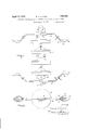
- FIG. 1 is a side elevation of an insulator string to which arcing horns which embody my invention in one form are applied;
- Fig. 2 is a plan view thereof
- Fig. 3 is a side elevation of an installation adapted for an insulator string arranged in horizontal position
- Fig. at is a similar view illustrating the ap- 7 plication of my invention to a string of insulators of the cap and pin type;
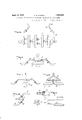
- Figs. 5 and 6 are side elevations at right angles to each other showing the application of my invention to a multiple string suspension insulator
- Fig. 7 is a plan view of an arcing tip detached from its support
- Fig. 8 is a section on the line 88, Fig. 7;
- Fig. 9 is a side elevation showing a modification of the terminal support.
- neither the arcing horn gaps nor the ring gaps provide any means which cause the are, when established therebetween, to travel away from the insulator. Consequently it is a common experience for the arc to strike from one of these terminals into the insulator, causing puncture of the insulator or injury to its associated metal parts.
- My invention eliminates the danger of in jury to the insulator by providing gap terminals which have the high speed characteristics of sphere terminals, and by setting these terminals at such spacing that when superpotential is impressed upon the line, the current does not flash over the insulator, but jumps the gap.
- My gap terminals are of such substantial size that the momentary play of the are at the point of initial formation, has little or no effect thereon even after repeated operation of the gap.
- my terminal construction is such that the arc is caused to move away from the area upon which it initially plays, and shifts to an area where fusion or volatilization has no effect upon the gap rating, and little effect upon the characteristic operation of the gap. This area is more remote from the insulator, and consequently the danger that the arc will strike into the insulator is minimized and practically eliminated.
- the installation shown in Fig. 1 comprises a string of insulators 15 of the link or Hewlett type, connected by an adapter fitting 16 at the upper end of the string to a suspension hook 17 by which the insulator string is hung from a grounded tower structure or the like.
- a second adapter fitting 18 similar to the fitting 16, engages the hanger 19 to which the cable supporting clamp (not shown) is attached.
- arcing horns 20 and 21 At opposite ends of the string, and secured thereto in any suitable fashion, are arcing horns 20 and 21 respectively, the upper horn 20- being secured to the adapter fitting 16 by the bolt 22, while the lower arcing horn 21 is secured to the hanger 19 by the bolt 23.
- the horns 20 and 21 may be economically formed from lengths of strap metal, each twisted in its central area to lie flat against the surface to which it is bolted and offset at its outer ends to form respectively downwardly and upwardly angled arms for the support of the renewable terminals 24.
- These terminals are preferably formed from cast metal, and are of substantial size.
- Each terminal has a shank 26 channeled in its lower face to embrace the end of supporting arms, to which it is adjustably secured by bolt 25.
- a series of bolt holes in the shank and in the supporting arms of the bar 20 or 21, provides convenient means for effecting adjustment of the terminals at opposite ends of the string to desired break-down spacing.
- the arcing terminals 24 are spoon shaped, and present opposed convex faces 27 ourvilinear in all directions to obtain a sphere gap effect at their proximate areas. These areas merge, however, into a more or less pointed tip 28 remote from the insulator string, and the tips 28 of opposed terminals are spaced farther apart than the convex areas 27.
- the terminals at opposite ends of the string thus present spheroidal faces toward each other at the point of closest spacing, and contracted tips spaced fart-her apart and farther from the protected insulator string.
- Fig. 8 I have illustrated the same invention applied to the arcing horns for a horizontally arranged string.
- the supporting bars 29 extend only upward from the insulator string.
- the usual tendency of an arc to rise between the horns is accentuated by the spoon form of the present areing tips.
- Fig. 4 I have shown the horn applied to the head of an insulator string in which the insulator units are of the cap and pin type.
- a supporting strip 80 is secured in any suitable fashion to the cap of the top insulating unit 31, and the arcing horn bars 32 and 33 are bolted or riveted thereto at 841 and 35.
- the arcing tips are of tne same construction as that above described.
- the invention may be applied to multi-string insulator suspensions, as illustrated in Figs. 5 and 6.
- the suspension yoke 36 supports insulator strings 37 and 38 at its opposite ends.
- the arcing born 89 is bolted or riveted to the flanges 40 of the yoke 36 at a point intermediate the insulator strings 37 and 38.
- Fig. 9 I have indicated a modified form of construction by means of which the arcing tips may be spaced more closely together Without spacing them at a greater distance from the insulator strings.
- F or this purpose I provide a Z-bar 41, the lower branch 42 of which is adapted to lie against the upwardly ofiset end of the arcing horn bar 21, and to be secured thereto by the bolts 25.
- the upper reach l3 of the Z-bar is pierced at intcrvals to afford detachable connection with the arcing terminal 2%.
- the terminals may be caused to approach each other more closely without spacing them further from the insulator string than is possible with a construction of the type shown in Figs. 1 to 6 inclusive.
- FIG. 7 and 8 illustrate its preferred construction. It will be noted that the terminal is recessed only at the shank portion thereof which is adapted to eml race the end of the bar 21, and that the body and tip of the spoon shaped terminal are solid. This construction not only provides a structure of substantial strength, but provides in the area upon which the arc plays a sufficient body of metal to absorb and dissipate the heat of the are without material injury to the structure.
- the gap rating may be safely permitted to approach the flashover rating of the insulator far more closely than has been regarded heretofore as permissible.
- the gap is perfectly safe to set the gap at 907; of the wet flash-over rating of an insulator which is exposed to the elements under service conditions. So far as I am aware, a gap of this rating has not heretofore been employed. If the insulator is housed against moisture and dust accumulations, the gap may be safely set much more closely to the full flash-over rating of the insulator.
- I claim 1 The method of protecting a power line insulator which comprises causing arc-over of superpotential through an air gap path in parallel with the insulator, and automatically shifting the are path away from the insulator to aspace beyond its original position.
- arcing horns respectively connected to the line and ground to form a gap substantially parallel to the insulator, said horns each having aterminal which has a spheroidal portion and a contracted tip at the side of the spheroidal portion away from the insulator.
- arcing horns respectively connected to the line and ground to form a gap substantially parallel to the insulator, said horns each having a terminal which has a spheroidal portion and a contracted tip at the side of the spheroidal portion away from the insulator, the surface of the terminal merging gradually from the spheroidal portion into the tip.
- arcing horns respectively connected to the line and ground to form a gap substantially parallel to the insulator, said horns each having a terminal which has a spheroidal portion and a contracted tip at the side of the spheroidal portion away from the insulator, the tip portions of the ground and line end terminals being spaced a greater extent than the spheroidal portions.
- arcing horns respectively connected to the line and ground to form a gap substantially parallel to the insulator, said horns each having a terminal which has a spheroidal portion and a contracted tip at the side of the spheroidal portion away from the insulator, the surface of the terminal merging gradually from the spheroidal portion into the tip, the tip portions of the ground and line end terminals being spaced a greater extent than the spheroidal portions.
- a high tension line insulator spaced arcing horns connected respectively to the line and ground, supporting means for said arcing horns, said horns each having a terminal which has a spheroidal portion and a contracted tip, the surface of each terminal merging gradually from the spheroidal portion into the tip and the tips being spaced farther from each other than the spheroidal portions and being directed away from said supporting means.
Description
April 12, 1932. H B, VINCENT 1,854,083
APPARATUS FOR PROTECTING SUPPORTING INSULATORS ON POWER LINES Filed April 19, 1927 2 Sheets-Sheet l fi' l? INVENTOR.
April 1932- H. B. VINCENT 1,854,083
APPARATUS FOR PROTECTING SUPPORTING LNSULATORS ON POWER LINES Filed April 19, 1927 2 Sheets-Sheet 2 I INVENTOR.
Patented Apr. 12, 1932 NETE STTES FATE OFFICE HAROLD BLANCHARD VINCENT, OF EAST LIVERPOOL, OHIO, ASSIGNOR TO THE R. THOMAS & SONS COMPANY, OF EAST LIVERPOOL, OHIO, A CORPORATION OF OHIO V APPARATUS FOR PROTECTING SUPPORTING INSULATORS ON POWER LINES Application filed. April 19,
My invention relates to method and apparatus for protecting insulators on power lines, and specifically, by limiting the voltage which may be impres ed on the supporting insulators.
My invention contemplates spaced terminals aii'ording an air gap path arranged in parallel with the supporting insulator and having a high speed break-down rating which approaches, but is lower than, the flash-over rating of the insulator; Consequently, when dangerous superpotential is impressed on the line, the current fiows between the air gap terminals and there is no flash-over on the insulator itself. The insulator is thus protected from injury incident to the initial flash-over on a ground discharge from the power line at its point of support.
My invention contemplates gap terminals having certain of the characteristics of sphere terminals, but so designed that on are formation therebetween the continued play of the arc occurs upon portions of the terminals other than that between which the arc initially strikes and by which the gap rating is determined. Consequently, the fusion or consumption of metal of the terminals by the heat of the are which plays thereon, does not aii ect the gap rating, and the latter is maintained substantially constant in spite of repeated arc formation.
My invention contemplates gap terminals so designed that upon are over therebetwee-n,
D I the arc is caused to move away from the associated insulator protected by the gap. This feature of my invention is of the greatest practical importance since it minimizes, or completely eliminates, danger of injury to the insulator by the striking of the are into the insulator from one of the terminals after formation between the latter.
My invention contemplates terminals of such character that they may be safely set 4.; at a gap rating far closer to the flash-over rating of the insulator than has heretofore been practicable. Incidentally my invention contemplates gap terminals which are adjnstably mounted so that their spacing may e.) be accurately determined to approach more 1927. Serial No. 184,987.
or less closely to the flash-over rating of the insulator.
My invention contemplates a method of protectin an insulator a ainst in'ur 0n arc D C over which comprises the discharge of superpotential across a high speed gap arranged in parallel with the insulator, followed by the deflection of the are into an ionized path more remote from the insulator than the path established by the are on its initial formation.
My invention maybe embodied in various forms of construction, and only the most commercially practicable embodiment thereof now known to me, is illustrated in the accompanying drawings, in which Fig. 1 is a side elevation of an insulator string to which arcing horns which embody my invention in one form are applied;
Fig. 2 is a plan view thereof;
Fig. 3 is a side elevation of an installation adapted for an insulator string arranged in horizontal position;
Fig. at is a similar view illustrating the ap- 7 plication of my invention to a string of insulators of the cap and pin type;
Figs. 5 and 6 are side elevations at right angles to each other showing the application of my invention to a multiple string suspension insulator;
Fig. 7 is a plan view of an arcing tip detached from its support;
Fig. 8 is a section on the line 88, Fig. 7; and
Fig. 9 is a side elevation showing a modification of the terminal support.
In power line installations of the type to which my invention relates, it is common practice to provide arcing horns or arcing rent, instead of striking betwen the gap terminals (of the common type mentioned) flashes over the surfaces of the insulator and may even puncture the latter or cause injury to its associated metal parts, before the arc is transferred to the arcing horns. This action is also characteristic of the ring terminals, which, as pointed out in the Nicholson Patent 966,584, receive the are only after it has formed and flared out into the zone occupied by the rings.
Moreover, when an arc plays upon a rod terminal, the tip is fused and volatilized by the heat of the are, so that the original spacing of the gap is increased, and the gap rating is altered. This establishes new and unknown conditions at the gap and of greater danger to the insulator since the gap rating between the tips has been increased and the arc plays longer on the insulator before shifting to the gap terminals-if indeed it shifts to these at all. If the original gap rating is to be restored (as it should be) a new tip must be installed.
Furthermore, neither the arcing horn gaps nor the ring gaps provide any means which cause the are, when established therebetween, to travel away from the insulator. Consequently it is a common experience for the arc to strike from one of these terminals into the insulator, causing puncture of the insulator or injury to its associated metal parts.
My invention eliminates the danger of in jury to the insulator by providing gap terminals which have the high speed characteristics of sphere terminals, and by setting these terminals at such spacing that when superpotential is impressed upon the line, the current does not flash over the insulator, but jumps the gap. My gap terminals are of such substantial size that the momentary play of the are at the point of initial formation, has little or no effect thereon even after repeated operation of the gap. Moreover, my terminal construction is such that the arc is caused to move away from the area upon which it initially plays, and shifts to an area where fusion or volatilization has no effect upon the gap rating, and little effect upon the characteristic operation of the gap. This area is more remote from the insulator, and consequently the danger that the arc will strike into the insulator is minimized and practically eliminated.
The installation shown in Fig. 1 comprises a string of insulators 15 of the link or Hewlett type, connected by an adapter fitting 16 at the upper end of the string to a suspension hook 17 by which the insulator string is hung from a grounded tower structure or the like.
At the lower end of the string a second adapter fitting 18, similar to the fitting 16, engages the hanger 19 to which the cable supporting clamp (not shown) is attached.
At opposite ends of the string, and secured thereto in any suitable fashion, are arcing horns 20 and 21 respectively, the upper horn 20- being secured to the adapter fitting 16 by the bolt 22, while the lower arcing horn 21 is secured to the hanger 19 by the bolt 23.
The horns 20 and 21 may be economically formed from lengths of strap metal, each twisted in its central area to lie flat against the surface to which it is bolted and offset at its outer ends to form respectively downwardly and upwardly angled arms for the support of the renewable terminals 24. These terminals are preferably formed from cast metal, and are of substantial size. Each terminal has a shank 26 channeled in its lower face to embrace the end of supporting arms, to which it is adjustably secured by bolt 25. A series of bolt holes in the shank and in the supporting arms of the bar 20 or 21, provides convenient means for effecting adjustment of the terminals at opposite ends of the string to desired break-down spacing.
The arcing terminals 24 are spoon shaped, and present opposed convex faces 27 ourvilinear in all directions to obtain a sphere gap effect at their proximate areas. These areas merge, however, into a more or less pointed tip 28 remote from the insulator string, and the tips 28 of opposed terminals are spaced farther apart than the convex areas 27. The terminals at opposite ends of the string thus present spheroidal faces toward each other at the point of closest spacing, and contracted tips spaced fart-her apart and farther from the protected insulator string.
When using arcing terminals of this type, the arc strikes between the convex surfaces 27 of the terminals, followed by outward movement away from the insulator to the tips 28. Repeated trials have demonstrated the uniformity of this phenomenon.
In explanation of the phenomenon, I have noted that when superpotential is impressed upon the line, corona appears at the tips 28 preceding the flash over between the convex surfaces 27. It is my impression that the corona formation at the tips io-nizes the current path between the tips, but not sufliciently to cause break down at this point before the arc snaps over between the convex areas 27. The ionization of the path between the tips 28 has, however, created a condition which causes the are to move outward into this path and thus away from the insulator string.
It would seem therefore that by the construction in question the combined effects of sphere and needle gaps are presented. As is well known, there is no corona formation between spherical surfaces preceding discharge therebetween. On the contrary, corona always forms between needle points preceding discharge. By my present construction the break down occurs between the spheroidal surfaces 27 by reason of the fact that the superpotential exceeds the break-down rating between these areas before the ionization of the atmosphere between the tips 28 so reduces the rating of the gap between these more distantly spaced points that the flash over can occur at the tips. This is advantageous since the body of the terminal at the areas 27 is better able to withstand the action of the are by reason of the greater volume and heat absorbing capacity of metal at this point than the tips 28. Pitting of the spheroidal areas 27 does not occur, or is so slight as to inappreciably afiect the rating of the gap, and such injury as results from the heat of the are is confined to the tips. Inasmuch as the gap rating is governed by the spacing of the convex areas 27, such injury to the tips as is occasioned by the are has no appreciable effect upon the action of the gap.
It has been suggested that the electrostatic influence of the insulator string itself has some effect in causing th are to move outward toward the tips of the terminals. Such is not my belief, however, since this influence would be present when the arcing tips are merely spherical, or spheroidal, and would cause a similar outward movement of the are. My experience is, however, that the arc does not move outward and away from the insulator string when the arcing tips are merely spherical or spheroidal.
In Fig. 8 I have illustrated the same invention applied to the arcing horns for a horizontally arranged string. In this in stance the supporting bars 29 extend only upward from the insulator string. In an installation of this type the usual tendency of an arc to rise between the horns is accentuated by the spoon form of the present areing tips.
The construction is of course applicable to other types of insulators than the link or Hewlett type illustrated in Figs. 1 to 3. Thus in Fig. 4 I have shown the horn applied to the head of an insulator string in which the insulator units are of the cap and pin type. A supporting strip 80 is secured in any suitable fashion to the cap of the top insulating unit 31, and the arcing horn bars 32 and 33 are bolted or riveted thereto at 841 and 35. The arcing tips are of tne same construction as that above described.
Similarly the invention may be applied to multi-string insulator suspensions, as illustrated in Figs. 5 and 6. Here the suspension yoke 36 supports insulator strings 37 and 38 at its opposite ends. The arcing born 89 is bolted or riveted to the flanges 40 of the yoke 36 at a point intermediate the insulator strings 37 and 38.
In Fig. 9 I have indicated a modified form of construction by means of which the arcing tips may be spaced more closely together Without spacing them at a greater distance from the insulator strings. F or this purpose I provide a Z-bar 41, the lower branch 42 of which is adapted to lie against the upwardly ofiset end of the arcing horn bar 21, and to be secured thereto by the bolts 25. The upper reach l3 of the Z-bar is pierced at intcrvals to afford detachable connection with the arcing terminal 2%. It is obvious that by interposing a Z-bar ll of this type between the arcing horn bar and the terminal 24:, the terminals may be caused to approach each other more closely without spacing them further from the insulator string than is possible with a construction of the type shown in Figs. 1 to 6 inclusive.
The detail views of the terminal (Figs. 7 and 8) illustrate its preferred construction. It will be noted that the terminal is recessed only at the shank portion thereof which is adapted to eml race the end of the bar 21, and that the body and tip of the spoon shaped terminal are solid. This construction not only provides a structure of substantial strength, but provides in the area upon which the arc plays a sufficient body of metal to absorb and dissipate the heat of the are without material injury to the structure.
The high speed sphere gap characteristic of these terminals makes it possible to space them much closer together than is possible with gap terminals of the type in common use, and consequcntl ,by means of their proximity, the danger of arc cascade to the insulator is greatly reduced in fact practically eliminated. liloreov'er, the gap rating may be safely permitted to approach the flashover rating of the insulator far more closely than has been regarded heretofore as permissible. Thus it is perfectly safe to set the gap at 907; of the wet flash-over rating of an insulator which is exposed to the elements under service conditions. So far as I am aware, a gap of this rating has not heretofore been employed. If the insulator is housed against moisture and dust accumulations, the gap may be safely set much more closely to the full flash-over rating of the insulator.
While I have described my invention in connection with various types of string insu lators it is obvious that the invention is not limited to use with string insulators. It may be applied to the pin and other types as well. I therefore claim the invention broadly.
Various modifications of construction by which the technical advantages of my invention are obtained will readily occur to those skilled in the art, without departing from what I claim as my invention.
I claim 1. The method of protecting a power line insulator which comprises causing arc-over of superpotential through an air gap path in parallel with the insulator, and automatically shifting the are path away from the insulator to aspace beyond its original position.
2. The method of protecting a vertically arranged power line insulator which com prises causing arc-over of superpotential through an air gap path substantially parline insulator, arcing horns respectively connected to the line and ground to form an arc gap substantially parallel to the insulator, said horns having opposed terminals shaped to afford sphere gap characteristics at their areas in closest proximity, and needle point characteristics at areas spaced further apart and laterally more remote from the insulator.
4. The combination with a high potential line insulator of arcing horns arranged at opposite ends of the insulator and respectively connected to line and to ground to form an arc gap substantially parallel to the insulator, said horns having opposed terminals shaped at their proximate areas to establish arc-over thereon without prior corona forma tion on the occurrence of superpotential on the line, and tips spaced further apart and more remote from the insulator at which corona occurs in advance of arc formation.
5. In combination with a high potential line insulator, arcing horns respectively connected to the line and ground to form a gap substantially parallel to the insulator, said horns each having aterminal which has a spheroidal portion and a contracted tip at the side of the spheroidal portion away from the insulator.
6. In combination with a high potential line insulator, arcing horns respectively connected to the line and ground to form a gap substantially parallel to the insulator, said horns each having a terminal which has a spheroidal portion and a contracted tip at the side of the spheroidal portion away from the insulator, the surface of the terminal merging gradually from the spheroidal portion into the tip.
7. In combination with a high potential line insulator, arcing horns respectively connected to the line and ground to form a gap substantially parallel to the insulator, said horns each having a terminal which has a spheroidal portion and a contracted tip at the side of the spheroidal portion away from the insulator, the tip portions of the ground and line end terminals being spaced a greater extent than the spheroidal portions.
8. In combination with a high potential line insulator, arcing horns respectively connected to the line and ground to form a gap substantially parallel to the insulator, said horns each having a terminal which has a spheroidal portion and a contracted tip at the side of the spheroidal portion away from the insulator, the surface of the terminal merging gradually from the spheroidal portion into the tip, the tip portions of the ground and line end terminals being spaced a greater extent than the spheroidal portions.
9. In combination, a high tension line insulator, spaced arcing horns connected respectively to the line and ground, supporting means for said arcing horns, said horns each having a terminal which has a spheroidal portion and a contracted tip, the surface of each terminal merging gradually from the spheroidal portion into the tip and the tips being spaced farther from each other than the spheroidal portions and being directed away from said supporting means.
In testimony whereof I have signed my name to this specification.
HAROLD BLANCHARD VINCENT.
Priority Applications (1)
| Application Number | Priority Date | Filing Date | Title |
|---|---|---|---|
| US184987A US1854083A (en) | 1927-04-19 | 1927-04-19 | Apparatus for protecting supporting insulators on power lines |
Applications Claiming Priority (1)
| Application Number | Priority Date | Filing Date | Title |
|---|---|---|---|
| US184987A US1854083A (en) | 1927-04-19 | 1927-04-19 | Apparatus for protecting supporting insulators on power lines |
Publications (1)
| Publication Number | Publication Date |
|---|---|
| US1854083A true US1854083A (en) | 1932-04-12 |
Family
ID=22679082
Family Applications (1)
| Application Number | Title | Priority Date | Filing Date |
|---|---|---|---|
| US184987A Expired - Lifetime US1854083A (en) | 1927-04-19 | 1927-04-19 | Apparatus for protecting supporting insulators on power lines |
Country Status (1)
| Country | Link |
|---|---|
| US (1) | US1854083A (en) |
-
1927
- 1927-04-19 US US184987A patent/US1854083A/en not_active Expired - Lifetime
Similar Documents
| Publication | Publication Date | Title |
|---|---|---|
| US2587587A (en) | Suspension insulator for hightension conductors | |
| US1854083A (en) | Apparatus for protecting supporting insulators on power lines | |
| US2559599A (en) | Electrical surge arrester | |
| US2164720A (en) | Lightning arrester | |
| US2135353A (en) | Arcing electrode | |
| US1233296A (en) | High-tension insulator. | |
| US1448773A (en) | Transmission-line insulator | |
| US2002042A (en) | Excess-voltage protective structure | |
| US2185263A (en) | Arc protecting device | |
| US1947321A (en) | Arcing horn for insulators | |
| US1277978A (en) | Lightning-arrester. | |
| US1715478A (en) | Cap for insulators | |
| US1802743A (en) | Transmission-line device | |
| US991749A (en) | Lightning-arrester. | |
| US2356052A (en) | Conductor support | |
| US2246303A (en) | Electrical discharge device | |
| US1690185A (en) | Transmission-line device | |
| GB304057A (en) | Improvements relating to electrical insulators | |
| US1940591A (en) | Protecing apparatus for insulators | |
| US1901572A (en) | Transmission line device | |
| US2282905A (en) | Discharge gap | |
| US1806170A (en) | Bracket and dead-end insulator | |
| US1529773A (en) | Fuse block | |
| US3471632A (en) | Ambient deionizing apparatus for insulators | |
| DE424878C (en) | Horn lightning arrester with induction-free resistance |