US185405A - Improvement in machines for making staples - Google Patents
Improvement in machines for making staples Download PDFInfo
- Publication number
- US185405A US185405A US185405DA US185405A US 185405 A US185405 A US 185405A US 185405D A US185405D A US 185405DA US 185405 A US185405 A US 185405A
- Authority
- US
- United States
- Prior art keywords
- wheels
- machines
- box
- improvement
- wire
- Prior art date
- Legal status (The legal status is an assumption and is not a legal conclusion. Google has not performed a legal analysis and makes no representation as to the accuracy of the status listed.)
- Expired - Lifetime
Links
- 238000010276 construction Methods 0.000 description 6
- 210000003414 Extremities Anatomy 0.000 description 2
- 238000005452 bending Methods 0.000 description 2
- 230000036633 rest Effects 0.000 description 2
Images
Classifications
-
- B—PERFORMING OPERATIONS; TRANSPORTING
- B21—MECHANICAL METAL-WORKING WITHOUT ESSENTIALLY REMOVING MATERIAL; PUNCHING METAL
- B21F—WORKING OR PROCESSING OF METAL WIRE
- B21F45/00—Wire-working in the manufacture of other particular articles
- B21F45/16—Wire-working in the manufacture of other particular articles of devices for fastening or securing purposes
- B21F45/24—Wire-working in the manufacture of other particular articles of devices for fastening or securing purposes of staples; of belt-fastening elements
Definitions
- This invention relates to machines for mak ing staples.
- the principle of operation and the particular construction of the machine are herein fully set forth, and made the subject of specific claims.
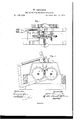
- Figure l is a top view of the machine, with part broken away to disclose the working parts beneath.
- Fig. 2 is a vertical section showing the cutting apparatus, and a side view of the wheels which bend and form the staple.
- the apparatus is mounted on suitable framework, as clearly represented.
- the machine consists of two distinct parts, one relating to the cutting and the other to the bending of the wire which forms the staple. These parts, though to some extent independent in their operation, act in unison, as they are arranged upon my machine.
- the first-named part, consisting of the cutting apparatus, consists of a fixed and movable cutters.
- the former (marked a) is made so as to be adjustable forward, and may be removed, if desired. It rests in a recess, and is held down by a strap, b.
- the fixed cutter is provided with a ledge, over which the wire or rod is passed, and the cutting-edge is inclined, as shown in Fig.1.
- the edge of the movable cutter is made to correspond to that of the fixed cutter, so that in moving past the latter it shears the wire in a diagonal line, and leaves it with pointed ends.
- the ledge over which the wire or rod is fed lies in direct line from the hole in the standard 0, through which it advances to the box (1, into which the piece falls when severed.
- This box is formed with inclined sides e e, and in apassage cut across the center of the box are two wheels, 9 g, the peripheries of which are nearly in contact, the space between being arranged to receive the pieces of wire or rod as they drop.
- These wheels are fixed on shafts h h, on the outer ends of which are cogged Wheels it, by which motion may be imparted to the wheels from any suitable motor.
- a strong stud On one of the wheels g is fixed a strong stud, It, so arranged that when the wheel is rotated inwardly the stud shall strike across the bottom of the box, through the opening made transversely through the said box, and carry with it the wire or rod, which has been dropped from the cutting mechanism.
- the opposite wheel has in its periphery a socket, is, fitted to receive the stud 70.
- Around both the stud and the socket are grooves m m, of the form of the staple to be made. These grooves are, in portions of the peripheries of the wheels, slightly raised.
- the bottom of the box is formed of a strong earn, cut in the middle for the wheelsv and the passage of the stud, and near the wheels preferably grooved, these shallow grooves serving to steady and guide the rod when carried down by the wheels.
- a which is pivoted in rear of the knife, and below it.
- This block is provided with a lever, 0, extending rearward.
- the construction is such that the knife is the extremity of the short arm of the lever, and the elevation of the long arm brings the knife down diagonally over the wire.
- This lever 0 is operated from a pin, 1),. in the side of one of the wheels through a lever, g, which is connected to the lever 0 by a bar, 4.
- the parts are so adjusted that the knivesshall sever the rod, and allow the severed part to drop to the bottom of the box just before the stud on the wheel crosses the lower part thereof.
- the wire as before stated, is introduced through a hole in the guide s, and its movement is limited by a stop, t, on the other end of the box.
- the dies and the machine may be made to suit any size of rod, and may be driven by hand or steam power.
Description
W. RENNARD.
MACHINE FOR MAKING STAPLES.
Patented Dec. 19, 1876.
THE GRAPH [C C(LNX UNITED rr'ras 'WILLIAM RENNARD, OF WHEELING, WEST VIRGINIA, ASSIGNOB ONE- HALF HIS RIGHT TO ARCHIBALD M. ADAMS, OF SAME PLACE.
IMPROVEMENT IN MACHINES FOR MAKING STAPLES- Speoification forming part of Letters Patent No. 185,405, dated December 19, 1876; application filed October 30, 1876.
To all whom it may concern.-
Be it known that I, WILLIAM RENNARD, of Wheeling, in the county of Ohio and State of West Virginia, have invented a new and Improved Machine for Making Staples; and I do hereby declare the following to be a full, clear, and exact description of the same, reference being had to the accompanying drawings, forming part of this specification.
This invention relates to machines for mak ing staples. The principle of operation and the particular construction of the machine are herein fully set forth, and made the subject of specific claims. I v
Figure l is a top view of the machine, with part broken away to disclose the working parts beneath. Fig. 2 is a vertical section showing the cutting apparatus, and a side view of the wheels which bend and form the staple.
The apparatus is mounted on suitable framework, as clearly represented.
The machine consists of two distinct parts, one relating to the cutting and the other to the bending of the wire which forms the staple. These parts, though to some extent independent in their operation, act in unison, as they are arranged upon my machine. The first-named part, consisting of the cutting apparatus, consists of a fixed and movable cutters. The former (marked a) is made so as to be adjustable forward, and may be removed, if desired. It rests in a recess, and is held down by a strap, b.
The fixed cutter is provided with a ledge, over which the wire or rod is passed, and the cutting-edge is inclined, as shown in Fig.1. The edge of the movable cutter is made to correspond to that of the fixed cutter, so that in moving past the latter it shears the wire in a diagonal line, and leaves it with pointed ends.
The ledge over which the wire or rod is fed lies in direct line from the hole in the standard 0, through which it advances to the box (1, into which the piece falls when severed. This box is formed with inclined sides e e, and in apassage cut across the center of the box are two wheels, 9 g, the peripheries of which are nearly in contact, the space between being arranged to receive the pieces of wire or rod as they drop. These wheels are fixed on shafts h h, on the outer ends of which are cogged Wheels it, by which motion may be imparted to the wheels from any suitable motor. On one of the wheels g is fixed a strong stud, It, so arranged that when the wheel is rotated inwardly the stud shall strike across the bottom of the box, through the opening made transversely through the said box, and carry with it the wire or rod, which has been dropped from the cutting mechanism. The opposite wheel has in its periphery a socket, is, fitted to receive the stud 70. Around both the stud and the socket are grooves m m, of the form of the staple to be made. These grooves are, in portions of the peripheries of the wheels, slightly raised. The bottom of the box is formed of a strong earn, cut in the middle for the wheelsv and the passage of the stud, and near the wheels preferably grooved, these shallow grooves serving to steady and guide the rod when carried down by the wheels.
Referring to the movable knife, it will be observed that it is fastened in a block, a, which is pivoted in rear of the knife, and below it. This block is provided with a lever, 0, extending rearward. The construction is such that the knife is the extremity of the short arm of the lever, and the elevation of the long arm brings the knife down diagonally over the wire. This lever 0 is operated from a pin, 1),. in the side of one of the wheels through a lever, g, which is connected to the lever 0 by a bar, 4. The parts are so adjusted that the knivesshall sever the rod, and allow the severed part to drop to the bottom of the box just before the stud on the wheel crosses the lower part thereof. The wire, as before stated, is introduced through a hole in the guide s, and its movement is limited by a stop, t, on the other end of the box.
The dies and the machine may be made to suit any size of rod, and may be driven by hand or steam power.
with .the box d, and with the cutting appev- 3. lhe combinationof the block n,.cerrying' ratus located on one side thereof, the conthe moving knife, the levens oend q', the construction permitting the severed piece of wire meeting-rod r, and the pin on the wheel 9, as or rod to drop into position where it may be set.fonth..
received by the wheels, as set forth. WILLIAM BERNARD.
2. The combination of the box which re- Witnesses.:., ceives the severed pieces, the guide s, the GRENV'ILIJE LEWIS,
knives, and the stop t, as set forth. MELVLLLE GHURGH.
Publications (1)
| Publication Number | Publication Date |
|---|---|
| US185405A true US185405A (en) | 1876-12-19 |
Family
ID=2254811
Family Applications (1)
| Application Number | Title | Priority Date | Filing Date |
|---|---|---|---|
| US185405D Expired - Lifetime US185405A (en) | Improvement in machines for making staples |
Country Status (1)
| Country | Link |
|---|---|
| US (1) | US185405A (en) |
-
0
- US US185405D patent/US185405A/en not_active Expired - Lifetime
Similar Documents
| Publication | Publication Date | Title |
|---|---|---|
| US31253A (en) | Machine | |
| US185405A (en) | Improvement in machines for making staples | |
| US314221A (en) | Cyeus m | |
| US436255A (en) | Excelsior-machine | |
| US516737A (en) | Shape-metal-cutting machine | |
| US236618A (en) | painter | |
| US264378A (en) | Otates | |
| US599952A (en) | Machine for making toe-calks for horseshoes | |
| US1007258A (en) | Staple forming and clenching machine. | |
| US354828A (en) | Wood and geobge h | |
| US498838A (en) | Machine for bending horseshoe-blanks | |
| US136340A (en) | Improvement in machines for forming staple-seams in leather | |
| US356734A (en) | Machine for making metallic shanks for boots | |
| USRE8003E (en) | Improvement in machines for making horseshoe-nails | |
| US234671A (en) | Barb bender and cutter | |
| US291966A (en) | Pruning implement | |
| US70374A (en) | Antoine st | |
| US408226A (en) | Horses hoe-blank-cutting machine | |
| US58577A (en) | Improvement in machinery for making nails and tacks | |
| US921558A (en) | Machine for making bolts. | |
| US212441A (en) | Improvement in staple-machines | |
| US119529A (en) | Improvement in machines for making staples | |
| US182843A (en) | Improvement in machines for forging horseshoe-nails | |
| US358874A (en) | Machine for gumming saws | |
| US222945A (en) | Improvement in machines for gutting locks in hoops |