US1854033A - Reel for dispensing coiled strip material - Google Patents
Reel for dispensing coiled strip material Download PDFInfo
- Publication number
- US1854033A US1854033A US511058A US51105831A US1854033A US 1854033 A US1854033 A US 1854033A US 511058 A US511058 A US 511058A US 51105831 A US51105831 A US 51105831A US 1854033 A US1854033 A US 1854033A
- Authority
- US
- United States
- Prior art keywords
- coiled strip
- coil
- reel
- casing
- embrace
- Prior art date
- Legal status (The legal status is an assumption and is not a legal conclusion. Google has not performed a legal analysis and makes no representation as to the accuracy of the status listed.)
- Expired - Lifetime
Links
Images

Classifications
-
- B—PERFORMING OPERATIONS; TRANSPORTING
- B21—MECHANICAL METAL-WORKING WITHOUT ESSENTIALLY REMOVING MATERIAL; PUNCHING METAL
- B21C—MANUFACTURE OF METAL SHEETS, WIRE, RODS, TUBES OR PROFILES, OTHERWISE THAN BY ROLLING; AUXILIARY OPERATIONS USED IN CONNECTION WITH METAL-WORKING WITHOUT ESSENTIALLY REMOVING MATERIAL
- B21C47/00—Winding-up, coiling or winding-off metal wire, metal band or other flexible metal material characterised by features relevant to metal processing only
- B21C47/16—Unwinding or uncoiling
- B21C47/22—Unwinding coils without reels or drums
Definitions
- This invention relates to the art of reeling a coiled strip of material and particularly resilient material.
- the invention has for its main object the provision of a'reel servingas a package for the coiled material as a bracket for support- I ing the coiled material in the store in Which it is displayed and sold, and as a dispensing device from which desired lengths of the ma led material maybe withdrawn and out
- a'reel servingas a package for the coiled material as a bracket for support- I ing the coiled material in the store in Which it is displayed and sold, and as a dispensing device from which desired lengths of the ma led material maybe withdrawn and out
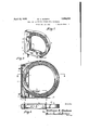
- Figure 1 is a perspective view of the device 32 of V the invention
- Figure 2 is a vertical section through the same
- v Figure 3 is a bottom elevation
- v V V s Figure 4 is a perspective View of the casing
- Figure 5 is a plan View of the stamped blank from which the casing is formed
- Figure 6 is a horizontal section through the reel illustratingthe function of the guiding lugs.
- the numeral 1 represents a substantially rigid casing which in the illustrated enibodi m'ent of the invention is L-shaped and of channel cross section having a back web 2,
- the back Web 2 is provided with means such asthe key hole slots 6 by means. of which the: casingv may be secured to screws or like devices inserted in a wall.
- the casing is preferably provided adjacent its ends with slots forming' straps 7 and 8 which afford means by which- 2.
- flexible band 9 is secured to said casing confrontingthe open side of the channel thereof. -15
- the flexible band is secured to the straps by Serial N0. 511,058.
- one end 10 of the flexible band protrudes an appreciable distance beyond the strap about which it is folded so as to provide a handleby which said band may be drawn further through the adjacent slot for the purpose of shortening the rotund portion of said band.
- the casing l is provided with a slot 11 adapted to receive the outer end of the coiled material as will presently appear.
- the flexible band 9 Prior to the insertion of the coil the flexible band 9 is secured only at one end to the casing, for example at the strap 7
- the closely wound coil is then positioned within the casing 1 with the free outer end thereof pro truding through the slot 11 v
- the flexible band 9 is then brought about the coil circumferentially and the free end of said band inserted. in the slot adjacent the strap 8, the band being pulled as tightly against thecoil as possible and the free end of said band being then folded outward against said strap.
- the flexible band thus. holds the coil firmly in positionsthe expansion of said coil inci dent to the resilient nature of the material causes a constantpressureoutwardly, against the flexible band which maintains the helices of said coil in solid formation and prevents said helices from slipping endwise out of position.
- the slack of the flexible band may be taken up by pulling the end 10 further through the slot from which it extends and securing it in its new position by again folding it about the strap 8.
- the coiled strip is formed with a bead or flange along one edge as for instance, in metallic binding so that it has a tendency to refuse to wind evenly but to slant off to one side of the coil continually as it is reeled or unreeled. It is therefore desirable to provide means for closely engaging the edges of the coil of material. WVith this end in view, the side flanges of the casing may be cut out to form lugs 12 and 13 which may be bent inwardly so as to closely engage the side edges of the coil for holdlng the helices thereof in place.
- Figure 5 is shown a blank'from which the casing 1 is constructed and it will be noted that the flanges i and 5 are provided with insongaging means comprising a tongue 14 stamped inward from one flange engageable with the walls of a slot 15 in the other flange.
- Figure 4 shows how, when the web is bent at right angles so as to form the back and bottom portions, and the flanges are turned up at right angles so as to form the channel, the tongues 1 1 may be alternately received in the slots 15.
- What is essential to the invention is a reel serving as a package, a bracket and a vending device for the coiled strip, having a portion which not only engages the coil to hold the same in place, but also inhibits the expansion of the coil, and which acts as a brake in retarding the unwinding movement of said coil imparted to it when the free end of the strip is drawn out for the purpose of cutting off desired lengths of the same.
- Reel for a coiled strip comprising means forming a substantially rigid casing for embracing a portion of said coil, and a flexible member secured to said means and embracing the outer circumferential face of all of that portion ofsaid coil not embraced by said casmg.
- Reel as claimed in claim 1 including means for adjusting the effective length of the flexible member.
- Reel for a coiled strip comprising a channel shaped casing having a web and side flanges, adapted to embrace a portion only of the coiled strip, and a flexible member secured to said casing and adapted to embrace the outer circumferential face of the remain ing portion of said coiled strip.
- Reel for a coiled strip comprising a channel-shaped casing having a web and side flanges, adapted to embrace a portion only of the coiled strip, and a flexible band secured to said casing confronting the open side thereof and adapted to embrace the outer circumferential face of the remaining portion of said coil.
- Reel for a coiled strip comprising a channel-shaped casing having a web and side flanges, adapted to embrace a portion only of said coiled strip, and a flexible band secured to the ends of said casing confronting the open side thereof and adapted to embrace the outer circumferential face of the remain ing portion of said coil, said casing having a slot from which the free end of said coiled strip is adapted to protrude and be withdrawn in unwinding said coil.
- Reel for a coiled strip comprising a channel-shaped casing having a web and side flanges, adapted to embrace a portion only of the coiled strip, the ends of said casing being formed with slots defining straps, and a flexible band secured about said straps confront-ing the open side of said casing and adapted to embrace the outer circumferential face of the remaining portion of said coil.
- Reel for a coiled strip comprising a channel-shaped casing having a web and side flanges adapted to embrace a portion only of the coiled strip, the ends of said casing being formed with slots defining straps, and a flexible band secured to said straps and adapted to embrace the outer circumferential face of the remaining portion of said coil, one end of said band protruding beyond the strap to which it is secured thereby providing a han- Sle for shortening the effective length of said and.
- Reel for a coiled strip comprising a channel-shaped casing having a web and side flanges, adapted to embrace a portion only of the coiled strip, certain of said webs being formed with lugs bendable toward said coiled strip for maintaining the helices thereof against endwise displacement, and a flexible member secured to said casing and adapted to embrace the outer circumferential face of the remaining portion of said coil.
- Reel for a coiled strip comprising an L-shaped casing adapted to embrace a portion only of the coiled strip, and a flexible band secured to the ends of said casing and adapted to embrace the outer circumferential face of the remaining portion of said coil, said casing being provided with means for supporting the same and with a slot for receiving the outer free end of said coiled strip.
- Reel for an expansible coil of strip material comprising a casing formed as a bracket having two adjacent sides diverging at an angle, and a flexible strip circumscribing said angle of divergence and secured to said sides, between which strip and said sides, said coil is adapted to be retained, said flexible strip conforming in part to the circumference of said coil and functioning as a brake to retard the unwinding of said coil.
Description
April 12, 1932. w. s. HUDSON REEL FOR DISPENSING COILED STRIP MATERIAL Filed Jan. 24, 19-31 2 Sheets-She'et 1 amniot- April 12, 1932. w. s. HUDSON 1,854,033
7 REEL FOR DISPENSING COILED STRIP MATERIAL Filed Jan. 24, 1931 2 Sheets-Sheet 2 William 5. Hudson Patented Apr. 12, 1 932 .;UNITED STATES 7, WILLIAM s. HUDSON, or PAINESVIL'LE, OHIO, ASSIGNOR TO THE rAmnsvrnnnivm'ren PATENT ol-"rlcr.
LIG IBINDING COMPANY, OF PAINESVILLE, OHIO, A CORPORATION OF OHIO REEL FOR DISPIEIYI'SING COIL-ET) STRIP MATERIAL Application filed January 24, 1931.
This invention relates to the art of reeling a coiled strip of material and particularly resilient material. V
The invention has for its main object the provision of a'reel servingas a package for the coiled material as a bracket for support- I ing the coiled material in the store in Which it is displayed and sold, and as a dispensing device from which desired lengths of the ma led material maybe withdrawn and out Other objects of the invention will appear as the following description of a preferred and practical embodiment thereof proceeds.
, The following specification is accompanied by drawings in whichsiniilar characters of reference have been employed throughout the several figures to designate identical parts Figure 1 is a perspective view of the device 32 of V the invention Figure 2 is a vertical section through the same; v Figure 3 is a bottom elevation; v V V s Figure 4: is a perspective View of the casing; Figure 5 is a plan View of the stamped blank from which the casing is formed; and Figure 6 is a horizontal section through the reel illustratingthe function of the guiding lugs.
Referring nowin detail to the several-figures the numeral 1 represents a substantially rigid casing which in the illustrated enibodi m'ent of the invention is L-shaped and of channel cross section having a back web 2,
a bottom web 3 and side flanges 4 and- 5.
It will be observed that the back Web 2 is provided with means such asthe key hole slots 6 by means. of which the: casingv may be secured to screws or like devices inserted in a wall. The casing is preferably provided adjacent its ends with slots forming' straps 7 and 8 which afford means by which- 2. flexible band 9 is secured to said casing confrontingthe open side of the channel thereof. -15 The flexible band is secured to the straps by Serial N0. 511,058.
folding the ends of said band about said straps. It will be noted that one end 10 of the flexible band protrudes an appreciable distance beyond the strap about which it is folded so as to provide a handleby which said band may be drawn further through the adjacent slot for the purpose of shortening the rotund portion of said band. The casing l is provided witha slot 11 adapted to receive the outer end of the coiled material as will presently appear.
Prior to the insertion of the coil the flexible band 9 is secured only at one end to the casing, for example at the strap 7 The closely wound coil is then positioned within the casing 1 with the free outer end thereof pro truding through the slot 11 v The flexible band 9 is then brought about the coil circumferentially and the free end of said band inserted. in the slot adjacent the strap 8, the band being pulled as tightly against thecoil as possible and the free end of said band being then folded outward against said strap. The flexible band thus. holds the coil firmly in positionsthe expansion of said coil inci dent to the resilient nature of the material causes a constantpressureoutwardly, against the flexible band which maintains the helices of said coil in solid formation and prevents said helices from slipping endwise out of position. p I e W M It being assumed that the reel is supported from the wall as described, the desiredlength of stripis withdrawn from the reelthrough the slot 11, the coil unwinding within the reel. The pressure of the coilagainst the flexible band creates a retardative friction whichwvhile permitting the coilto unwind, prevents its unwinding so freely asto become loose with the risk of its helices slipping endwiseout of place. r
When the coil becomes somewhat depleted and pressure againstthe flexible band di minishes, the slack of the flexible band may be taken up by pulling the end 10 further through the slot from which it extends and securing it in its new position by again folding it about the strap 8.
It may happen that the coiled strip is formed with a bead or flange along one edge as for instance, in metallic binding so that it has a tendency to refuse to wind evenly but to slant off to one side of the coil continually as it is reeled or unreeled. It is therefore desirable to provide means for closely engaging the edges of the coil of material. WVith this end in view, the side flanges of the casing may be cut out to form lugs 12 and 13 which may be bent inwardly so as to closely engage the side edges of the coil for holdlng the helices thereof in place.
In Figure 5 is shown a blank'from which the casing 1 is constructed and it will be noted that the flanges i and 5 are provided with in terengaging means comprising a tongue 14 stamped inward from one flange engageable with the walls of a slot 15 in the other flange. Figure 4 shows how, when the web is bent at right angles so as to form the back and bottom portions, and the flanges are turned up at right angles so as to form the channel, the tongues 1 1 may be alternately received in the slots 15.
It is to be understood that the specific form of the blank is immaterial to the invention, and that the invention does not concern itself particularly with the means provided for securing the side flanges together.
What is essential to the invention is a reel serving as a package, a bracket and a vending device for the coiled strip, having a portion which not only engages the coil to hold the same in place, but also inhibits the expansion of the coil, and which acts as a brake in retarding the unwinding movement of said coil imparted to it when the free end of the strip is drawn out for the purpose of cutting off desired lengths of the same.
It is to be understood also that the details of construction as shown and described are to be considered as merely exemplary, and not as imposing any limitations upon the invention which are not included in the scope of the appended claims.
What I claim is:
1. Reel for a coiled strip comprising means forming a substantially rigid casing for embracing a portion of said coil, and a flexible member secured to said means and embracing the outer circumferential face of all of that portion ofsaid coil not embraced by said casmg.
2. Reel as claimed in claim 1 including means for adjusting the effective length of the flexible member.
3. Reel for a coiled strip comprising a channel shaped casing having a web and side flanges, adapted to embrace a portion only of the coiled strip, and a flexible member secured to said casing and adapted to embrace the outer circumferential face of the remain ing portion of said coiled strip.
4:. Reel for a coiled strip comprising a channel-shaped casing having a web and side flanges, adapted to embrace a portion only of the coiled strip, and a flexible band secured to said casing confronting the open side thereof and adapted to embrace the outer circumferential face of the remaining portion of said coil.
5. Reel for a coiled strip comprising a channel-shaped casing having a web and side flanges, adapted to embrace a portion only of said coiled strip, and a flexible band secured to the ends of said casing confronting the open side thereof and adapted to embrace the outer circumferential face of the remain ing portion of said coil, said casing having a slot from which the free end of said coiled strip is adapted to protrude and be withdrawn in unwinding said coil.
6. Reel for a coiled strip comprising a channel-shaped casing having a web and side flanges, adapted to embrace a portion only of the coiled strip, the ends of said casing being formed with slots defining straps, and a flexible band secured about said straps confront-ing the open side of said casing and adapted to embrace the outer circumferential face of the remaining portion of said coil.
7. Reel for a coiled strip as claimed in claim 6, the casing being provided with a slot through the free end of the coiled strip is adapted to protrude and be withdrawn in unwinding said coil.
8. Reel for a coiled strip comprising a channel-shaped casing having a web and side flanges adapted to embrace a portion only of the coiled strip, the ends of said casing being formed with slots defining straps, and a flexible band secured to said straps and adapted to embrace the outer circumferential face of the remaining portion of said coil, one end of said band protruding beyond the strap to which it is secured thereby providing a han- Sle for shortening the effective length of said and.
9. Reel for a coiled strip comprising a channel-shaped casing having a web and side flanges, adapted to embrace a portion only of the coiled strip, certain of said webs being formed with lugs bendable toward said coiled strip for maintaining the helices thereof against endwise displacement, and a flexible member secured to said casing and adapted to embrace the outer circumferential face of the remaining portion of said coil.
10. Reel for a coiled strip comprising an L-shaped casing adapted to embrace a portion only of the coiled strip, and a flexible band secured to the ends of said casing and adapted to embrace the outer circumferential face of the remaining portion of said coil, said casing being provided with means for supporting the same and with a slot for receiving the outer free end of said coiled strip.
11. Reel for an expansible coil of strip material comprising a casing formed as a bracket having two adjacent sides diverging at an angle, and a flexible strip circumscribing said angle of divergence and secured to said sides, between which strip and said sides, said coil is adapted to be retained, said flexible strip conforming in part to the circumference of said coil and functioning as a brake to retard the unwinding of said coil. 7
In testimony whereof I aflix my signature.
' WILLIAM S. HUDSON.
Priority Applications (1)
| Application Number | Priority Date | Filing Date | Title |
|---|---|---|---|
| US511058A US1854033A (en) | 1931-01-24 | 1931-01-24 | Reel for dispensing coiled strip material |
Applications Claiming Priority (1)
| Application Number | Priority Date | Filing Date | Title |
|---|---|---|---|
| US511058A US1854033A (en) | 1931-01-24 | 1931-01-24 | Reel for dispensing coiled strip material |
Publications (1)
| Publication Number | Publication Date |
|---|---|
| US1854033A true US1854033A (en) | 1932-04-12 |
Family
ID=24033279
Family Applications (1)
| Application Number | Title | Priority Date | Filing Date |
|---|---|---|---|
| US511058A Expired - Lifetime US1854033A (en) | 1931-01-24 | 1931-01-24 | Reel for dispensing coiled strip material |
Country Status (1)
| Country | Link |
|---|---|
| US (1) | US1854033A (en) |
Cited By (2)
| Publication number | Priority date | Publication date | Assignee | Title |
|---|---|---|---|---|
| US4094473A (en) * | 1977-05-09 | 1978-06-13 | Salvino Lawrence P | Portable device for supporting a roll of aluminum sheeting for dispensing |
| US4206885A (en) * | 1979-07-02 | 1980-06-10 | Salvino Lawrence P | Portable device for supporting a roll of sheeting for dispensing |
-
1931
- 1931-01-24 US US511058A patent/US1854033A/en not_active Expired - Lifetime
Cited By (2)
| Publication number | Priority date | Publication date | Assignee | Title |
|---|---|---|---|---|
| US4094473A (en) * | 1977-05-09 | 1978-06-13 | Salvino Lawrence P | Portable device for supporting a roll of aluminum sheeting for dispensing |
| US4206885A (en) * | 1979-07-02 | 1980-06-10 | Salvino Lawrence P | Portable device for supporting a roll of sheeting for dispensing |
Similar Documents
| Publication | Publication Date | Title |
|---|---|---|
| US1830250A (en) | Outlet box fitting | |
| US2510939A (en) | Ruler construction | |
| US2175045A (en) | Coiled material | |
| US1854033A (en) | Reel for dispensing coiled strip material | |
| US2052341A (en) | Reel | |
| US2527401A (en) | Combined package and reel for coiled wire | |
| US1964280A (en) | Tape measure | |
| US2610812A (en) | Packages for twine, rope, and the like | |
| US1923456A (en) | Package for strip or like materials | |
| US2549098A (en) | Measuring tape | |
| US1899279A (en) | Photographic film reel | |
| US3625502A (en) | Power spring with keeper and bridle | |
| US2140729A (en) | Spool | |
| US2155771A (en) | Control for the unreeling of coiled material from drums | |
| US8262014B1 (en) | Device for storing and dispensing flexible tubing | |
| US2161540A (en) | Supply package for stapling machines | |
| US2036720A (en) | Coilable metal tape | |
| US1151971A (en) | Plaster-spool container. | |
| US2310140A (en) | Band saw package | |
| US3437281A (en) | Tape reel | |
| US2005677A (en) | Coilable measuring rule | |
| US2614772A (en) | Package of coreless tube wound bundle of twine | |
| US3537667A (en) | Reel | |
| US1049281A (en) | Head for music-roll spools. | |
| US2134918A (en) | Venetian blind ladder-web roll construction |