US1854026A - Salvaging apparatus - Google Patents
Salvaging apparatus Download PDFInfo
- Publication number
- US1854026A US1854026A US439910A US43991030A US1854026A US 1854026 A US1854026 A US 1854026A US 439910 A US439910 A US 439910A US 43991030 A US43991030 A US 43991030A US 1854026 A US1854026 A US 1854026A
- Authority
- US
- United States
- Prior art keywords
- gripping
- frame
- arms
- pontoons
- pontoon
- Prior art date
- Legal status (The legal status is an assumption and is not a legal conclusion. Google has not performed a legal analysis and makes no representation as to the accuracy of the status listed.)
- Expired - Lifetime
Links
Images


Classifications
-
- B—PERFORMING OPERATIONS; TRANSPORTING
- B63—SHIPS OR OTHER WATERBORNE VESSELS; RELATED EQUIPMENT
- B63C—LAUNCHING, HAULING-OUT, OR DRY-DOCKING OF VESSELS; LIFE-SAVING IN WATER; EQUIPMENT FOR DWELLING OR WORKING UNDER WATER; MEANS FOR SALVAGING OR SEARCHING FOR UNDERWATER OBJECTS
- B63C7/00—Salvaging of disabled, stranded, or sunken vessels; Salvaging of vessel parts or furnishings, e.g. of safes; Salvaging of other underwater objects
- B63C7/28—Refloating stranded vessels
-
- B—PERFORMING OPERATIONS; TRANSPORTING
- B63—SHIPS OR OTHER WATERBORNE VESSELS; RELATED EQUIPMENT
- B63C—LAUNCHING, HAULING-OUT, OR DRY-DOCKING OF VESSELS; LIFE-SAVING IN WATER; EQUIPMENT FOR DWELLING OR WORKING UNDER WATER; MEANS FOR SALVAGING OR SEARCHING FOR UNDERWATER OBJECTS
- B63C7/00—Salvaging of disabled, stranded, or sunken vessels; Salvaging of vessel parts or furnishings, e.g. of safes; Salvaging of other underwater objects
- B63C7/06—Salvaging of disabled, stranded, or sunken vessels; Salvaging of vessel parts or furnishings, e.g. of safes; Salvaging of other underwater objects in which lifting action is generated in or adjacent to vessels or objects
- B63C7/08—Salvaging of disabled, stranded, or sunken vessels; Salvaging of vessel parts or furnishings, e.g. of safes; Salvaging of other underwater objects in which lifting action is generated in or adjacent to vessels or objects using rigid floats
-
- B—PERFORMING OPERATIONS; TRANSPORTING
- B63—SHIPS OR OTHER WATERBORNE VESSELS; RELATED EQUIPMENT
- B63C—LAUNCHING, HAULING-OUT, OR DRY-DOCKING OF VESSELS; LIFE-SAVING IN WATER; EQUIPMENT FOR DWELLING OR WORKING UNDER WATER; MEANS FOR SALVAGING OR SEARCHING FOR UNDERWATER OBJECTS
- B63C7/00—Salvaging of disabled, stranded, or sunken vessels; Salvaging of vessel parts or furnishings, e.g. of safes; Salvaging of other underwater objects
- B63C7/16—Apparatus engaging vessels or objects
- B63C7/20—Apparatus engaging vessels or objects using grabs
Definitions
- GAMBA 1 1,854,026 I SALVAGING APPARATUS Filed March 29, 1950 6 .Sheets -Shevet 1 v 1 Q P BY ATTORN A ril 12, 1932.
- F. GAMBA 6 SALVAGING APPARATUS I Filed March 29, 1950 6 Sheets-Sheet 2 INVENTOR F7471 (Eu-ca 66M J4 W W ATTORN Y April 12, 1932.
- F, BA 1,854,026 I SALVAGING APPARATUS Filed March 29, 1950 6 Sheets-Sheet 2 INVENTOR F7471 (Eu-ca 66M J4 W W ATTORN Y April 12, 1932.
- This invention relates to improvementsin apparatus for raising sunken vesselsand for conducting salvaging operations of like nature, and more particularly refers to improvements in apparatus of the character] specified in which means are provided for gripping the vessel or other sunken body and raise it to the surface by virtue of the buoyancy of the apparatus itself.
- the primary object of this invention is to provide a novel and improved apparatus of the character specified which is adapted to be floated to a position directly over the sunken vessel, so as to be submerged where gripping means with which the apparatus is pro- Vided can be made to automatically grip the vessel for the purpose of subsequently lifting
- Another object is to provide in apparatus of the character specified comprising means for gripping a sunken vessel, buoyant means p for effecting the gripping action and for subsequently raising the apparatus together with the sunken vessel to the surface.
- a further obj ect is to provide in apparatus for raising sunken vessels or other submerged bodies, improved means for utilizing the buoyancy of pontoons or floats associated therewith in a manner causing the gripping means controlled by said pontoons or floats to V exert a gripping force the value of which is considerably greater than the lifting force exerted by said pontoons or floats.
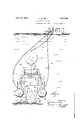
- FIG. l is an endelevation illustrating an apparatus embodying my invention in a certain position and with its arms gripping a sunken vessel therebetween; h r
- Fig. 2 is an end elevation showing the apparatus floating upon the water after having raised the sunken vessel;
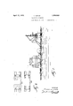
- Fig. 3 is a fragmentary end elevation partly sectioned illustrating'more in detail the construction of the apparatus
- Fig. 4 isa fragmentary view in perspective thereof; 7
- Fig. 5 is a fragmentary plan view partly sectioned of the same;
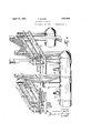
- Fig. 6 is a fragmentary view in prespective illustrating the vertically sliding connection between adjoining float elements
- Fig. 7 is a detail view in cross section of" one of the float elements-showing types of intake and exhaust valves which may be used in connection therewith and 1 Fig. 8 is a fragmentary front elevation of the central operation of a cross member and corresponding transversal member, illustrating how the width of the frame may be varied to suit requirements.
- My improved apparatus consists essentially of an elongated frame comprising a p1u-' 'rality of cross members 10, 11, 12 arranged in longitudinal series in spaced parallel relation to one another, and longitudinal members such as 13, 14, 15, 16 connecting theends of adjoining cross'meinbers completing the rigid frameor structure.
- each end of each cross member is formed with a vertical opening adapted to slidably receive uprights such as 17 18, the upper ends of which are rigidly connected by a' transversal'member 19, said members 17, 18,
- each upright 17 18 carries" a float or pontoon, such as 20, 21, which may be filled with water or emptied by suitable means provided to this end, said means com prising flexible tubular connections between the said floats and pontoons and the surface of the water, as shown at 22, 23 in Fig. 1.
- each end of each cross member 101112 is also provided with a horizontal pivotal support such as 24, 25 on which is mounted a gripping arm 26, 27.
- Said gripping arms preferably consist'of a rigid truss structure comprising a main substantially vertical member such as 2829, and two converging truss members 3031,.3233 attached atone end to members 2829 and at the other end to supporting members'34-35, mounted on pivots 2425.
- each member 28-29 is provided with an inwardly directed grip member 36, 3-7 and the upper end which projectsabove transversal member 19 is connected to said transversal member by one or member 19 is moved upwardly in relation to the underlying .cross member 10, the toggle system will be expanded causing the gripping arms to swing about their respective pivots so as to cause inward movement of their gripping members 86, 37 toward each other.
- This function of the toggle arms is illustrated in Fig. 1 where it is seen that transversal member 19 has been forced upwardly with respect tocross member 10 causing the gripping members 36, 37 at the lower end of the gripping arms 28, 29 to-grip the underside of a sunken vessel 40.
- means are provided for automatically retaining the gripping arms in their contracted position so as to insure an elfective gripping action when the apparatus is raised to the surface.
- Fig. 3 it will be seen that the upper end of gripping arm 27 is pivotally connected at 43 to a hollow link 44 formed with a longitudinal chamber 45, and that the 'upperend41 of gripping arm 26 is pivotally connected at 46 to a stem member 47, the outer end of which is inserted within chamber 45 of link 44, thus forming with said link 44 an articulated expansible connection between the upper end of the gripping arms.
- stem 47 is provided with indentations 48 adapted to be engaged by a pawl 49 pivotally mounted at- 50 adjacent the outer end of link 44.
- the sense of said indentations is such as to cause the pawl to normally prevent inward movement of stem 4'? and link 44 with respect to eacn other, while allowing free outward movement thereof, a spring 51 normally retaining said pawl in its engaged position.
- each set of uprights 1'4", 18 together with the floats or pontoons de ending therefrom and the toggle connection between their transversal memher 19 and the corresponding gripping arms is independent of the other sets so that the movements of the gripping arms of one set are not affected by the movements of the gripping arms of another set.
- each inverted U frame is preferably provided with an upwardly projecting link 52 tothe upper end of which can be connected a float or pontoon 58,-the connection between links 52 and said floats or pontoons 53 being preferably of a detachable nature.
- the floats or pontoons 20, 21 are prcfer bly so proportioned as to possess sufficient buoyancy when empty to float not only the apparatus itself but also the weight of such vessels as the apparatus may be designed to handle.
- Floats or pontoons 53 are also preferably so proportioned as to be capable alone of floating the same weight.
- the apparatus In salvaging operations directed to the raising of a sunken vessel, the apparatusis first floated upon the surface directly above the vessel, its floats 20, 21 being at the time empty and its floats 53 being detached therefrom; said floats being connected by means of flexible hose 22, 23 to suitable air pumps or compressors carried by the salvaging boat 54, while floats 53 are connected to the pumps or compressors by similar flexible hose 55.
- V lVater is then gradually pumped in floats or pontoons 20, 21 causing the device to sink to a point where the upper end of links 52 being close to the surface of the water connection can be estab lished between said links and floats or pontoons 53.
- the buoyancy of the floats or pontoons is utilized'first to exert a powerful grip against the sides of the sunken vessel, the gripping arms being maintained in their gripping position and positively prevented from spreading apart by the locking arrangement shown at 48, 49.
- the same floats or pontoons are uti lized for'raising the sunken vessel to'the surface, the entire operation being controlled from the surface, the cooperation ofdivers being rarely required after the correctposition of the sunken vessel has been located.
- the floats or pontoons 20, 21 composing each longitudinal series may be totally independent of one another but are preferably interconnected in a manner permitting each float or pontoonto move vertically with respect to the others. 'Such an'arrangement increases the rigidity of the system and may. be obtained by providing the ends of adj oining floats or pontoonswith a verticallysliding connection such-as shown in Figs. -5, 6.
- one'of the ends 56 of intermediate float or pontoon 57 in each longitudinal row is provided with a vertical shoe 58 having outwardly projecting flanges 59, 60 slid able within a vertical C shaped guiding m'emher 61 carried by the adjacent end 62 of float or pontoon 63 in the same row.
- the opposite end 64 of said float or pontoon 57 is similarly equipped with a vertical C sectioned guiding member 65 within which may slidea vertical shoe 66 carried by the inner end 67 of float or pontoon 21.
- Fig. 7 I illustrate one of the arrangements which can be used to admit to or dis- "charge water from the floats or pontoons.
- 68 designates an exhaust Valve comprising a ball 69 normally held against its seat 70 by a spring 71, the tension of which can be adjusted by a bushing 72 provided with perforations or outlets 7 3.
- 74 designates an inlet valve comprising a ball 75 normally rest- .ing against its seat 7 6 due to the pressure exerted by a spring 77 held in position by a cap 78.
- the body of the valve 74 is provided with an inlet 7 9, through which water may be admitted to the inside of the float when suc:
- lifting force of the floats or pontoons can be made to exert a gripping force of much I greater value against the sides of thesunken grip can be obtained vesssel, so that a secure by the gripping arms.
- the main frame can members running uninterruptedly from side 'toside and from end to end, if desired. Howbe composed of rigid ever, in practice, I prefer to make the frame of sectional construction, in such a manner that the same can be made wider or narrower,
- cross members extending between the sides of the frame are split in the center as shown at 80 in'Fig. 3 and are connected by tie plates Slime-king a rigid system therewith.
- tie plates 81, 82 can be removed and longer tie plates 83, 84 can be substituted as shown in Fig. 8.
- the sides of the frame can be split midway of the distance between two succeeding cross members, as shown at :85, 86 in Fig. 5 and the adjoining ends of the plied in a number of different ways and by means of devices differing in their construction from that shown and described, without departing from the inventive idea; the drawings will therefore be understood as being intended for illustrative purposes only and not in a limiting sense. Accordingly, I reserve the right to carry my invention into practice in all those ways and manners which may enter, fairly, into the scope of the appended claims.
- the combination with a frame, gripping arms adapted to receive a sunken object between them pivotally mounted upon said frame, a pontoon, and means for admitting water to and for ejecting it from said pontoon, of toggle connections interposed between said gripping arms and said pontoon, causing the lifting force due to the buoyancy of said pontoon to be applied to said li ting arms at an increased ratio,'to move them to gripping position, and means preventing return movement of said gripping arms.
- An apparatus of the class described comprising, in combination, a frame, a pair of gripping arms pivotally-mounted one at each side of said frame, said arms having upwardly projecting extensions, a toggle connection between said extensions, buoyant means for operating said connection to move said arms to gripping position, and means for locking said arms in'said position.
- An apparatus of the class described comprising, in combination, a frame, a pair of gripping arms pivotally mounted one at each side of said frame, said arms having upwardly projecting extensions, a pontoon adjacent thelower end-of each gripping arm, a carrierfor each pontoon,capable of vertical displacement with respect to said frame, and toggle connections between said carriers and said extensions, adapted to transmit'to said arms the movements of said carriers.
- An apparatus of the class described comprising, in combination, a frame, a pair of gripping arms pivotally mounted one at each side of said frame, said arms having upwardly projecting extensions, a pontoon adjacent the lower end of each" gripping arm, a carrier for each pontoon, capable of vertical displacement with respect to said frame, a cross member connecting the upper ends of said carriers, toggle connections between said cross member and said extensions, and means for admitting water to and for ejecting it from said pontoons.
- An apparatus of the class described comprising, in combination, a frame, a pair of gripping arms pivotally mounted one at each side of said frame, said arms having upwardly orojecting extensions, a toggle connection etween said extensions, buoyant meansfor operating said connection to move said arms to gripping position, means for locking said arms in said position.
- An apparatus of the class described comprising, in combination, a frame, a pair of gripping arms having-upwardly projecting extensions, a pontoon adjacent the lower end of each gripping-arm, a carrier for each pontoon, capable of vertical displacement with respect to said frame,:a cross member connecting the upper ends of said, carriers, toggle connections between said cross member and said extensions,,an additional pontoon above said toggle connection, attached thereto, andmeans for admitting waterto and for ejecting it from said pontoons.
- An apparatus of the class described comprising, in combination, a frame, a pair of grippin arms having upwardly projecting extensions, a pontoon adjacentthe lower end of each gripping arm, a carrierfor each. pontoon, capable of vertical displacement with respect to said frame, a cross member connecting the upper ends of said carriers, toggle connections between said cross member and said extensions, an additional pontoon above said toggle connection, detachably attached thereto, andmeans for admitting water to and for ejecting it from said pontoons.
- An apparatus of the class described comprising, in combination, an elongatedframe, a pluralityof longitudinally spaced gripping arms pivotally mounted at each side of said frame, toggle connectionsbetween oppositely positioned arms, pontoons connected 7 to said toggle connections, and meansfor admitting water to and for ejecting it from said pontoons, independently of one another.
- An apparatus of the class described com gripping arms pivotally mounted at each side of said frame, toggle connections between oppositely positioned arms, a pontoon adjacent the lower end of each arm, a carrier for each pontoon vertically movable in relation to said frame, a cross member connecting each set of oppositely positioned carriers, attached to the corresponding toggle connection, and means for admitting water to and for ejecting it from said pontoons, independently of one another.
- An apparatus of the class described comprising, in combination, an elongated frame, a plurality of longitudinally spaced gripping arms pivotally mounted at each side of said frame, toggle connections between oppositely positioned arms, a pontoon adjacent the lower end of each arm, a carrier for each pontoon vertically movable in relation to said frame, a cross member connecting each set of oppositely positioned carriers, attached to the corresponding toggle connection, an additional pontoon detachably attached to and projecting above each toggle connection, and means for admitting water to and for ejecting it from said pontoons, independently of one another.
- An apparatus of the class described comprising, in combination, an elongated frame, a plurality of longitudinally spaced gripping arms pivotally mounted at each side of said frame, toggle connections between oppositely position arms, means for locking said arms in their gripping position, a pontoon adjacent the lower end of each arm, a carrier for each pontoon vertically movable in relation to said frame, a cross member connecting each set of oppositely positioned carriers, attached to the corresponding toggle connection, and means for admitting Water to and for ejecting it from said pontoons, independently of one another.
- An apparatus of the class described comprising, in combination, an elongated frame, a plurality'of longitudinally spaced gripping arms pivotally mounted at each side of said frame, toggle connections between oppositely positioned arms, a pontoon adjacent the lower end of each arm, the pon-i toons at each side being interlocking with one another end to endso as to restrain them against relative movement in a transversal direction, while permitting relative move v tached tothe' corresponding toggle connection, and means for admitting water to-and for ejecting it from said -pontoons,independently of one another.
- An apparatus of the class. describedi comprising, in combination, an. elongated frame comprising two sides, transversal split connecting members therebetween, and demountable tie members rigidly connecting the split portions of said connecting members, a plurality of longitudinally spaced gripping arms pivotally mounted at each side of said frame, toggle connections between oppositely positioned arms, a pontoon adjacent the lower end of each arm, a carrier for each pontoon vertically movable in relation to said frame, a split cross member connecting each set of oppositely positioned carriers, attached to the corresponding toggle connection, demountable tie members rigidly connecting the split portions of said cross members, and means for admitting water to and for ejecting it from said pontoons, independently of one another.
- An apparatus of the class described comprising, in comprising, in combination, an elongated frame comprising two sides, each consisting of a plurality of units demountably connected end to end, transversal split connecting members between oppositely positioned units, and demountable tie members rigidly connecting the split portions of said connecting members, a plurality of longitudinally spaced gripping arms pivotally mounted at each side of said frame, toggle connections between oppositely positioned arms, a pontoon adjacent the lower end of each arm, a carrier for each pontoon vertically movable in relation to said frame, a split cross member connecting each set of oppositely positioned carriers, attached to the corresponding toggle connection, demountable tie members rigidly connecting the split portions of said cross members, and means for admitting water to and for ejecting it from said pontoons, independently of one another.
- An, apparatus of the class described comprising, in combination, an elongated frame comprising two sides, each consisting ,units, and demountable tie members rigidly connecting the split portions of said connecting members, a plurality of longitudinally spaced gripping arms pivotally mounted at each side of said frame, toggle connections between oppositely positioned arms, means for locking said arms in their gripping position, a pontoon adjacent the lower end of each arm, a, carrier: for each pontoon vertically movable in relation to said frame a split cross member connecting each set of oppositely positioned carriers, attached to the corresponding toggle connection, demountable tie members rigidly connecting the split portions ofsaid cross members, and means for admitting Water to and for ejecting it from said pontoons, independently of 0. one another.
Description
April 12, 1932. GAMBA 1 1,854,026 I SALVAGING APPARATUS Filed March 29, 1950 6 .Sheets -Shevet 1 v 1 Q P BY ATTORN A ril 12, 1932. F. GAMBA 6 SALVAGING APPARATUS I Filed March 29, 1950 6 Sheets-Sheet 2 INVENTOR F7471 (Eu-ca 66M J4 W W ATTORN Y April 12, 1932. F, BA 1,854,026
SALVAGING APPARATUS Filed March 29, 1930 6 Sheets-$heet 3 INVENTOR j Francesca Germ Ad Z c7 ATTORNEY April 12, 1932. GAMBA 1,854,026
SALVAGING APPARATUS Filed March 29, 1930 6 Sheets-Sheet 4 INVENTOR Fran cc: ca 64" W W ATTORN April 12, 1932. GAMBA 1354 026 SALYAGING APPARATUS Filed March 29, 1950 e Sheets-Sheet 5 IN VEN TOR A TTORNE April 12, 1932. F. GAMBA SALVAGING APPARATUS Filed March 29, 1-930 6 Shaer.s'-Sheei INVENTOR Y w Mm an 5 A C L e C n N. P m
Patented Apr. 12, 1932 ice A ENToi FRANCESCO GAMIBA, or NEW YORK, n. Y., ASSIGNOR, BY manor AND MESNE SSIGN- MENTS, ro GAMBA MARINE SALVAGE oonroit 'rron, CORPORATION OFIIDVELA- WARE sALvAeINo ArrAn TUs 1 Application filed. March 29, 1930. Seria1"N0. 439,910.
This invention relates to improvementsin apparatus for raising sunken vesselsand for conducting salvaging operations of like nature, and more particularly refers to improvements in apparatus of the character] specified in which means are provided for gripping the vessel or other sunken body and raise it to the surface by virtue of the buoyancy of the apparatus itself.
The generally accepted method of raising so one side andit is also'diflicult forthe divers I to do efiicient Work encumbered as they are by their diving suits and by the air connections. At times it is also impossibleto properly tie up the pontoons onto the vessel or to pass the chains under the hull which may be partly sunk in mud or sand.
The primary object of this invention is to provide a novel and improved apparatus of the character specified which is adapted to be floated to a position directly over the sunken vessel, so as to be submerged where gripping means with which the apparatus is pro- Vided can be made to automatically grip the vessel for the purpose of subsequently lifting Another object is to provide in apparatus of the character specified comprising means for gripping a sunken vessel, buoyant means p for effecting the gripping action and for subsequently raising the apparatus together with the sunken vessel to the surface.
A further obj ect is to provide in apparatus for raising sunken vessels or other submerged bodies, improved means for utilizing the buoyancy of pontoons or floats associated therewith in a manner causing the gripping means controlled by said pontoons or floats to V exert a gripping force the value of which is considerably greater than the lifting force exerted by said pontoons or floats.
Other objects and advantages of the present invention will more fully appear as the description proceeds and will beset forth and claimed in the appended claims. v
An embodiment of my invention is illustrated by way of example in the accompanying drawings, in which? Fig. l is an endelevation illustrating an apparatus embodying my invention in a certain position and with its arms gripping a sunken vessel therebetween; h r
Fig. 2 is an end elevation showing the apparatus floating upon the water after having raised the sunken vessel; V
Fig. 3 is a fragmentary end elevation partly sectioned illustrating'more in detail the construction of the apparatus;
Fig. 4 isa fragmentary view in perspective thereof; 7
Fig. 5 is a fragmentary plan view partly sectioned of the same; i
Fig. 6 is a fragmentary view in prespective illustrating the vertically sliding connection between adjoining float elements; 7
Fig. 7 is a detail view in cross section of" one of the float elements-showing types of intake and exhaust valves which may be used in connection therewith and 1 Fig. 8 is a fragmentary front elevation of the central operation of a cross member and corresponding transversal member, illustrating how the width of the frame may be varied to suit requirements.
My improved apparatus consists essentially of an elongated frame comprising a p1u-' 'rality of cross members 10, 11, 12 arranged in longitudinal series in spaced parallel relation to one another, and longitudinal members such as 13, 14, 15, 16 connecting theends of adjoining cross'meinbers completing the rigid frameor structure. a
Each end of each cross member is formed with a vertical opening adapted to slidably receive uprights such as 17 18, the upper ends of which are rigidly connected by a' transversal'member 19, said members 17, 18,
19 forming inverted U frames adapted to move vertically through the end openings of the corresponding cross memberslO, 11 or 12, 7
. The lower end of each upright 17 18 carries" a float or pontoon, such as 20, 21, which may be filled with water or emptied by suitable means provided to this end, said means com prising flexible tubular connections between the said floats and pontoons and the surface of the water, as shown at 22, 23 in Fig. 1.
Each end of each cross member 101112 is also provided with a horizontal pivotal support such as 24, 25 on which is mounted a gripping arm 26, 27. Said gripping arms preferably consist'of a rigid truss structure comprising a main substantially vertical member such as 2829, and two converging truss members 3031,.3233 attached atone end to members 2829 and at the other end to supporting members'34-35, mounted on pivots 2425. The lower end of each member 28-29 is provided with an inwardly directed grip member 36, 3-7 and the upper end which projectsabove transversal member 19 is connected to said transversal member by one or member 19 is moved upwardly in relation to the underlying .cross member 10, the toggle system will be expanded causing the gripping arms to swing about their respective pivots so as to cause inward movement of their gripping members 86, 37 toward each other. This function of the toggle arms is illustrated in Fig. 1 where it is seen that transversal member 19 has been forced upwardly with respect tocross member 10 causing the gripping members 36, 37 at the lower end of the gripping arms 28, 29 to-grip the underside of a sunken vessel 40.
By virtue of this arrangement, means are provided for automatically retaining the gripping arms in their contracted position so as to insure an elfective gripping action when the apparatus is raised to the surface.
This can be effected in a number of ways as will be understood, for instance, by adopting the arrangement illustrated in the draw ings, comprising a telescopic connection be tween the upper end 41, 42 of the gripping arms, and means for retaining the two members of which the telescopic connection is composed in their expanded position reached by virtue of the swinging movement of the gripping arms.
Referring to Fig. 3 it will be seen that the upper end of gripping arm 27 is pivotally connected at 43 to a hollow link 44 formed with a longitudinal chamber 45, and that the 'upperend41 of gripping arm 26 is pivotally connected at 46 to a stem member 47, the outer end of which is inserted within chamber 45 of link 44, thus forming with said link 44 an articulated expansible connection between the upper end of the gripping arms.
The outer end of stem 47 is provided with indentations 48 adapted to be engaged by a pawl 49 pivotally mounted at- 50 adjacent the outer end of link 44.
The sense of said indentations is such as to cause the pawl to normally prevent inward movement of stem 4'? and link 44 with respect to eacn other, while allowing free outward movement thereof, a spring 51 normally retaining said pawl in its engaged position.
t will be observed that each set of uprights 1'4", 18 together with the floats or pontoons de ending therefrom and the toggle connection between their transversal memher 19 and the corresponding gripping arms is independent of the other sets so that the movements of the gripping arms of one set are not affected by the movements of the gripping arms of another set. This confers great flexibility to the operation of the device, enabling as it does sets of gripping arms to exert their gripping action in varying degrees according tothecontour of the vessel at the gripping points. V
The transversal member 19 of each inverted U frame is preferably provided with an upwardly projecting link 52 tothe upper end of which can be connected a float or pontoon 58,-the connection between links 52 and said floats or pontoons 53 being preferably of a detachable nature.
The floats or pontoons 20, 21 are prcfer bly so proportioned as to possess sufficient buoyancy when empty to float not only the apparatus itself but also the weight of such vessels as the apparatus may be designed to handle.
Floats or pontoons 53 are also preferably so proportioned as to be capable alone of floating the same weight. In salvaging operations directed to the raising of a sunken vessel, the apparatusis first floated upon the surface directly above the vessel, its floats 20, 21 being at the time empty and its floats 53 being detached therefrom; said floats being connected by means of flexible hose 22, 23 to suitable air pumps or compressors carried by the salvaging boat 54, while floats 53 are connected to the pumps or compressors by similar flexible hose 55. lVater is then gradually pumped in floats or pontoons 20, 21 causing the device to sink to a point where the upper end of links 52 being close to the surface of the water connection can be estab lished between said links and floats or pontoons 53. V
This being done the sinking operations are continued bypumping water in all the floats or pontoons, this making it possiblefor the inverted U frames 171819 to move downwardly with respect to the main frame to the :position shown in Fig. 3 where the gripping arms are in their spread out position. In this position the gripping arms are spread apart a distance sufficient to permit the device to descend to the bottom with a set of gripping 7 arms at each side of the sunken vessel. 7 This being done, water is forced out of floats or pontoons 53 and is also partially. forced out of floats or pontoons20, 21. The buoyancy thus imparted to the floats or POIltOOIlSlS transmitted to tranversal members 19 which will be forced upwardly in relation to the main frame, with the result that the toggles will be expanded and the lower ends'of the gripping arms will be forced inwardly and underneath the hull of the vessel as shown in Fig. l. The upper end of the gripping "buoyancy of the system will eventually cause the salvaging apparatus'together with the vessel gripped thereby to rise to the surface,
where pumping operations can be resumed with respect to floats or pontoons 20, 21 and floats or pontoons 53 are preferably detached from the apparatus altogether, leaving the apparatus in the conditionshownin Fig. 2.
It will be observed that by virtue of this arrangement the buoyancy of the floats or pontoons is utilized'first to exert a powerful grip against the sides of the sunken vessel, the gripping arms being maintained in their gripping position and positively prevented from spreading apart by the locking arrangement shown at 48, 49. As the buoyancy increases, the same floats or pontoons are uti lized for'raising the sunken vessel to'the surface, the entire operation being controlled from the surface, the cooperation ofdivers being rarely required after the correctposition of the sunken vessel has been located.
The gripping'action is thus rendered practically automatic and independent of chains, cables and other elements which are likely to slip or to snap. r
The floats or pontoons 20, 21 composing each longitudinal series may be totally independent of one another but are preferably interconnected in a manner permitting each float or pontoonto move vertically with respect to the others. 'Such an'arrangement increases the rigidity of the system and may. be obtained by providing the ends of adj oining floats or pontoonswith a verticallysliding connection such-as shown in Figs. -5, 6.
According to the arrangement shown in said figure, one'of the ends 56 of intermediate float or pontoon 57 in each longitudinal row is provided with a vertical shoe 58 having outwardly projecting flanges 59, 60 slid able within a vertical C shaped guiding m'emher 61 carried by the adjacent end 62 of float or pontoon 63 in the same row.
The opposite end 64 of said float or pontoon 57 is similarly equipped with a vertical C sectioned guiding member 65 within which may slidea vertical shoe 66 carried by the inner end 67 of float or pontoon 21. virtue of this arrangement as stated, the float or pontoons in the same longitudinal row are free to move vertically with respect to one another but act as a rigid system when stresses other than vertical occur;
In Fig. 7 I illustrate one of the arrangements which can be used to admit to or dis- "charge water from the floats or pontoons.
In the same 68 designates an exhaust Valve comprising a ball 69 normally held against its seat 70 by a spring 71, the tension of which can be adjusted by a bushing 72 provided with perforations or outlets 7 3. 74 designates an inlet valve comprising a ball 75 normally rest- .ing against its seat 7 6 due to the pressure exerted by a spring 77 held in position by a cap 78. The body of the valve 74 is provided with an inlet 7 9, through which water may be admitted to the inside of the float when suc:
tion is exerted through hose 23.
' When water is to be forced out of the float the operation is reversed by admitting air under pressure through hose 23 instead of creating a suction therethrough. The water will therefore be forced out through valve- 68 against the action of spring 71.
Although the apparatus has been shown as depending entirely upon the buoyancy of the floats or pontoons in order to raise its own weight and that of the sunken vessel, it 7 is obvious that if: desired, additional means may be provided for assisting the action of I the pontoons.
It will. beobserved that by proper proportioning of the various elements described, the
lifting force of the floats or pontoons can be made to exert a gripping force of much I greater value against the sides of thesunken grip can be obtained vesssel, so that a secure by the gripping arms.
The main frame can members running uninterruptedly from side 'toside and from end to end, if desired. Howbe composed of rigid ever, in practice, I prefer to make the frame of sectional construction, in such a manner that the same can be made wider or narrower,
or longer or shorter, whenever desired to suit various conditions. In order to make this possible, the cross members extending between the sides of the frame are split in the center as shown at 80 in'Fig. 3 and are connected by tie plates Slime-king a rigid system therewith.
In-the same manner,thetransversal members of theiinverted U frames are split in the center and are connected by tie plates such. as If on account of the size of the sunken vessel it should be necessary or desirable to provide a wider gripping structure, tie plates 81, 82 can be removed and longer tie plates 83, 84 can be substituted as shown in Fig. 8.
In a similar manner, the sides of the frame can be split midway of the distance between two succeeding cross members, as shown at :85, 86 in Fig. 5 and the adjoining ends of the plied in a number of different ways and by means of devices differing in their construction from that shown and described, without departing from the inventive idea; the drawings will therefore be understood as being intended for illustrative purposes only and not in a limiting sense. Accordingly, I reserve the right to carry my invention into practice in all those ways and manners which may enter, fairly, into the scope of the appended claims.
I claim:
1. in apparatus of the class described, the combination, with a frame, gripping arms adapted to receive a sunken object between them pivotally mounted upon said frame, a pontoon, and means for admitting water to and for ejecting it from said pontoon, of toggle connections interposed between said gripping arms and said pontoon, causing the lifting force due to the buoyancy of said pontoon to be applied to said li ting arms at an increased ratio,'to move them to gripping position, and means preventing return movement of said gripping arms.
2. An apparatus of the class described comprising, in combination, a frame, a pair of gripping arms pivotally-mounted one at each side of said frame, said arms having upwardly projecting extensions, a toggle connection between said extensions, buoyant means for operating said connection to move said arms to gripping position, and means for locking said arms in'said position.
'3. An apparatus of the class described comprising, in combination, a frame, a pair of gripping arms pivotally mounted one at each side of said frame, said arms having upwardly projecting extensions, a pontoon adjacent thelower end-of each gripping arm, a carrierfor each pontoon,capable of vertical displacement with respect to said frame, and toggle connections between said carriers and said extensions, adapted to transmit'to said arms the movements of said carriers.
4. An apparatus of the class described comprising, in combination, a frame, a pair of gripping arms pivotally mounted one at each side of said frame, said arms having upwardly projecting extensions, a pontoon adjacent the lower end of each" gripping arm, a carrier for each pontoon, capable of vertical displacement with respect to said frame, a cross member connecting the upper ends of said carriers, toggle connections between said cross member and said extensions, and means for admitting water to and for ejecting it from said pontoons.
5. An apparatus of the class described comprising, in combination, a frame, a pair of gripping arms pivotally mounted one at each side of said frame, said arms having upwardly orojecting extensions, a toggle connection etween said extensions, buoyant meansfor operating said connection to move said arms to gripping position, means for locking said arms in said position.
6. An apparatus of the class described comprising, in combination, a frame, a pair of gripping arms having-upwardly projecting extensions, a pontoon adjacent the lower end of each gripping-arm, a carrier for each pontoon, capable of vertical displacement with respect to said frame,:a cross member connecting the upper ends of said, carriers, toggle connections between said cross member and said extensions,,an additional pontoon above said toggle connection, attached thereto, andmeans for admitting waterto and for ejecting it from said pontoons.
7 An apparatus of the class described comprising, in combination, a frame, a pair of grippin arms having upwardly projecting extensions, a pontoon adjacentthe lower end of each gripping arm, a carrierfor each. pontoon, capable of vertical displacement with respect to said frame, a cross member connecting the upper ends of said carriers, toggle connections between said cross member and said extensions, an additional pontoon above said toggle connection, detachably attached thereto, andmeans for admitting water to and for ejecting it from said pontoons.
'8. An apparatus of the class described comprising, in combination, an elongatedframe, a pluralityof longitudinally spaced gripping arms pivotally mounted at each side of said frame, toggle connectionsbetween oppositely positioned arms, pontoons connected 7 to said toggle connections, and meansfor admitting water to and for ejecting it from said pontoons, independently of one another.
9. An apparatus of the class described com gripping arms pivotally mounted at each side of said frame, toggle connections between oppositely positioned arms, a pontoon adjacent the lower end of each arm, a carrier for each pontoon vertically movable in relation to said frame, a cross member connecting each set of oppositely positioned carriers, attached to the corresponding toggle connection, and means for admitting water to and for ejecting it from said pontoons, independently of one another.
11. An apparatus of the class described comprising, in combination, an elongated frame, a plurality of longitudinally spaced gripping arms pivotally mounted at each side of said frame, toggle connections between oppositely positioned arms, a pontoon adjacent the lower end of each arm, a carrier for each pontoon vertically movable in relation to said frame, a cross member connecting each set of oppositely positioned carriers, attached to the corresponding toggle connection, an additional pontoon detachably attached to and projecting above each toggle connection, and means for admitting water to and for ejecting it from said pontoons, independently of one another.
12. An apparatus of the class described comprising, in combination, an elongated frame, a plurality of longitudinally spaced gripping arms pivotally mounted at each side of said frame, toggle connections between oppositely position arms, means for locking said arms in their gripping position, a pontoon adjacent the lower end of each arm, a carrier for each pontoon vertically movable in relation to said frame, a cross member connecting each set of oppositely positioned carriers, attached to the corresponding toggle connection, and means for admitting Water to and for ejecting it from said pontoons, independently of one another.
,13. An apparatus of the class described comprising, in combination, an elongated frame, a plurality'of longitudinally spaced gripping arms pivotally mounted at each side of said frame, toggle connections between oppositely positioned arms, a pontoon adjacent the lower end of each arm, the pon-i toons at each side being interlocking with one another end to endso as to restrain them against relative movement in a transversal direction, while permitting relative move v tached tothe' corresponding toggle connection, and means for admitting water to-and for ejecting it from said -pontoons,independently of one another.
'14. An apparatus, of the class. describedi comprising, in combination, an. elongated frame comprising two sides, transversal split connecting members therebetween, and demountable tie members rigidly connecting the split portions of said connecting members, a plurality of longitudinally spaced gripping arms pivotally mounted at each side of said frame, toggle connections between oppositely positioned arms, a pontoon adjacent the lower end of each arm, a carrier for each pontoon vertically movable in relation to said frame, a split cross member connecting each set of oppositely positioned carriers, attached to the corresponding toggle connection, demountable tie members rigidly connecting the split portions of said cross members, and means for admitting water to and for ejecting it from said pontoons, independently of one another.
15. An apparatus of the class described comprising, in comprising, in combination, an elongated frame comprising two sides, each consisting of a plurality of units demountably connected end to end, transversal split connecting members between oppositely positioned units, and demountable tie members rigidly connecting the split portions of said connecting members, a plurality of longitudinally spaced gripping arms pivotally mounted at each side of said frame, toggle connections between oppositely positioned arms, a pontoon adjacent the lower end of each arm, a carrier for each pontoon vertically movable in relation to said frame, a split cross member connecting each set of oppositely positioned carriers, attached to the corresponding toggle connection, demountable tie members rigidly connecting the split portions of said cross members, and means for admitting water to and for ejecting it from said pontoons, independently of one another.
16. An, apparatus of the class described comprising, in combination, an elongated frame comprising two sides, each consisting ,units, and demountable tie members rigidly connecting the split portions of said connecting members, a plurality of longitudinally spaced gripping arms pivotally mounted at each side of said frame, toggle connections between oppositely positioned arms, means for locking said arms in their gripping position, a pontoon adjacent the lower end of each arm, a, carrier: for each pontoon vertically movable in relation to said frame a split cross member connecting each set of oppositely positioned carriers, attached to the corresponding toggle connection, demountable tie members rigidly connecting the split portions ofsaid cross members, and means for admitting Water to and for ejecting it from said pontoons, independently of 0. one another.
FRANCESCO GAMBA.
Priority Applications (1)
| Application Number | Priority Date | Filing Date | Title |
|---|---|---|---|
| US439910A US1854026A (en) | 1930-03-29 | 1930-03-29 | Salvaging apparatus |
Applications Claiming Priority (1)
| Application Number | Priority Date | Filing Date | Title |
|---|---|---|---|
| US439910A US1854026A (en) | 1930-03-29 | 1930-03-29 | Salvaging apparatus |
Publications (1)
| Publication Number | Publication Date |
|---|---|
| US1854026A true US1854026A (en) | 1932-04-12 |
Family
ID=23746642
Family Applications (1)
| Application Number | Title | Priority Date | Filing Date |
|---|---|---|---|
| US439910A Expired - Lifetime US1854026A (en) | 1930-03-29 | 1930-03-29 | Salvaging apparatus |
Country Status (1)
| Country | Link |
|---|---|
| US (1) | US1854026A (en) |
Cited By (7)
| Publication number | Priority date | Publication date | Assignee | Title |
|---|---|---|---|---|
| US2675681A (en) * | 1954-04-20 | Marine apparatus | ||
| US3782317A (en) * | 1971-09-01 | 1974-01-01 | Kriedt F | Submersible salvage unit |
| US4150503A (en) * | 1972-08-22 | 1979-04-24 | Pierre Lespinasse | Apparatus for excavation and earth removal from aquatic bottoms |
| US4713896A (en) * | 1981-04-10 | 1987-12-22 | Jennens Eric G | Inshore submersible amphibious machines |
| FR2852917A1 (en) * | 2003-03-26 | 2004-10-01 | Saipem Sa | SEALED COMPARTMENT RECEPTACLE AND METHOD OF PLACING IT TO RECOVER POLLUTANT EFFLUENTS FROM A EPAVE |
| WO2004087495A2 (en) * | 2003-03-26 | 2004-10-14 | Saipem S.A. | Device and method for stabilising and controlling the lowering or raising of a heavy structure between the surface and the bed of the sea |
| US20150259054A1 (en) * | 2010-11-30 | 2015-09-17 | Jon Khachaturian | Marine Lifting Apparatus |
-
1930
- 1930-03-29 US US439910A patent/US1854026A/en not_active Expired - Lifetime
Cited By (12)
| Publication number | Priority date | Publication date | Assignee | Title |
|---|---|---|---|---|
| US2675681A (en) * | 1954-04-20 | Marine apparatus | ||
| US3782317A (en) * | 1971-09-01 | 1974-01-01 | Kriedt F | Submersible salvage unit |
| US4150503A (en) * | 1972-08-22 | 1979-04-24 | Pierre Lespinasse | Apparatus for excavation and earth removal from aquatic bottoms |
| US4713896A (en) * | 1981-04-10 | 1987-12-22 | Jennens Eric G | Inshore submersible amphibious machines |
| FR2852917A1 (en) * | 2003-03-26 | 2004-10-01 | Saipem Sa | SEALED COMPARTMENT RECEPTACLE AND METHOD OF PLACING IT TO RECOVER POLLUTANT EFFLUENTS FROM A EPAVE |
| WO2004087495A2 (en) * | 2003-03-26 | 2004-10-14 | Saipem S.A. | Device and method for stabilising and controlling the lowering or raising of a heavy structure between the surface and the bed of the sea |
| WO2004087495A3 (en) * | 2003-03-26 | 2004-11-18 | Saipem Sa | Device and method for stabilising and controlling the lowering or raising of a heavy structure between the surface and the bed of the sea |
| US20070089656A1 (en) * | 2003-03-26 | 2007-04-26 | Saipem S.A. | Device and a method for stabilizing and controlling the lowering or raising of a structure between the surface and the bed of the sea |
| US20150259054A1 (en) * | 2010-11-30 | 2015-09-17 | Jon Khachaturian | Marine Lifting Apparatus |
| US9701376B2 (en) * | 2010-11-30 | 2017-07-11 | Jon Khachaturian | Marine lifting apparatus |
| US10286985B2 (en) | 2010-11-30 | 2019-05-14 | Versabar, Inc. | Marine lifting apparatus |
| US10960959B2 (en) | 2010-11-30 | 2021-03-30 | Versabar, Inc. | Marine lifting apparatus |
Similar Documents
| Publication | Publication Date | Title |
|---|---|---|
| US2955626A (en) | Pipe lines for loading and unloading ships and other vessels | |
| US3270698A (en) | Floating dry dock | |
| US1681533A (en) | Submarine drill | |
| NO751300L (en) | ||
| US1854026A (en) | Salvaging apparatus | |
| US1555080A (en) | Hose boat | |
| US2508800A (en) | Equipment for salvaging submerged objects | |
| US2379904A (en) | Multiple unit floating dry dock | |
| US256608A (en) | The eckpfit-t-ltkosraphihg co | |
| US1293899A (en) | Apparatus for raising sunken vessels. | |
| US3541986A (en) | Submersible salvage unit and method of operation | |
| US3315627A (en) | Pneumatically operated floating dry dock | |
| US1691738A (en) | Salvaging apparatus | |
| US1740231A (en) | Rapid salvage system for submarines | |
| US1368787A (en) | Method for recovering sunken vessels | |
| US1043411A (en) | Floating dry-dock. | |
| US4276846A (en) | Recovery apparatus | |
| US287156A (en) | Camel for lightening vessels | |
| US1308168A (en) | I lanoobaph co | |
| US1332384A (en) | Ship-raising apparatus | |
| US2829615A (en) | Salvaging apparatus | |
| US650134A (en) | Apparatus for submarine pipe-laying. | |
| US1912428A (en) | Salvage apparatus | |
| US1296662A (en) | Dry-dock. | |
| US2420384A (en) | Pontoon |