US1853970A - Fuel feeding device - Google Patents
Fuel feeding device Download PDFInfo
- Publication number
- US1853970A US1853970A US501744A US50174430A US1853970A US 1853970 A US1853970 A US 1853970A US 501744 A US501744 A US 501744A US 50174430 A US50174430 A US 50174430A US 1853970 A US1853970 A US 1853970A
- Authority
- US
- United States
- Prior art keywords
- fuel
- burette
- fuel feeding
- feeding device
- casing
- Prior art date
- Legal status (The legal status is an assumption and is not a legal conclusion. Google has not performed a legal analysis and makes no representation as to the accuracy of the status listed.)
- Expired - Lifetime
Links
Images
Classifications
-
- G—PHYSICS
- G01—MEASURING; TESTING
- G01F—MEASURING VOLUME, VOLUME FLOW, MASS FLOW OR LIQUID LEVEL; METERING BY VOLUME
- G01F9/00—Measuring volume flow relative to another variable, e.g. of liquid fuel for an engine
- G01F9/006—Measuring volume flow relative to another variable, e.g. of liquid fuel for an engine with mechanic means
Definitions
- the invention relates to fuel feeding devices, and more particularly to a device for accurately metering a given quantity of fuel to an engine for test purposes.
- One object of the invention is to provide a device which may be connected in the fuel supply line of a motor vehicle without interfering with the normal operation thereof, and yet permit of interrupting the regular supply and measuring a definite quantity of fuel as it is fed to an internal combustion engine, and thereby determine the distance the vehicle traverses for a given amount of fuel.
- Another object is to provide a device of simple and durable construction which mayV bereadily attached toa vehicle for test purposes, and used for measuring any desired number of times without interfering with the operation of the vehicle or the device.
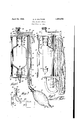
- Figure 1 is a vertical sectional View of the invention.
- FIG. 2 is a side eleva-tion view of the invention partly broken away.
- Figure 3 Ais a diagrammatic view onV a ⁇ reduced scale showing the invention applied to a motor vehicle fuel supply mechanism.
- the numeral 10 indicates a cylindrical casing preferably formed of sheet metal and fastened by screws 11 to ⁇ the peripheral flanges l2 and 13 around a top plate 14 and a bottom plate 15 respectively.
- the top plate 14 also has the laterally extending raised portion 22 on its upper side provided with the inlet passage 23 and relief passages 24, 241. Both the inlet and relief passages extend along the raised portion 22 of the top, and then downward into the space within the flange 16 of the top plate 14, the inlet being extended to form a spout 280 within the center of the space formed by the flange 16, while the relief passage where it extends downward is provided with a valve screw 26.
- valve screw 26 is threaded and screwed downward into a correspondingly threaded boss 27 on the top plate 14, and has the head 28 which when screwed down closes the passage 241, and when screwed up opens the p-assage but meets the pin 29 which prevents complete removal of the valve.
- the raised portion 22,0f the top plate 14 extends beyond the cylindrical casing 10,and has the downward projection 30 forming a hook which may be hung on to the glass 31 of an automobile door, and also provides an orilice 25 through which thestrap 32 is passed.
- the inlet passage 23 has the pipe 33 fitted into the under side of the top just outside the 'casing l0 and extendeddownwardly through the opening 34in the bottom plate 15.
- a pair of concave rubber suction discs 35 are fastened to the lugs 36A on the bottom plate 15, and hold the device very firmly to position against the glass.
- the inlet pipe 33 is connected by a rubber tube 37 with a pumping mechanism such as a rubber bulb 40 fitted with oneway valves 41 and 42 and a continuing rubber tube 38 suitably connected with the reguis connected to the uncoupled supply pipe, so that the gasoline will fioW to the carburetor 45 of the engine 46.
- a pumping mechanism such as a rubber bulb 40 fitted with oneway valves 41 and 42 and a continuing rubber tube 38 suitably connected with the reguis connected to the uncoupled supply pipe, so that the gasoline will fioW to the carburetor 45 of the engine 46.
- the relief valve 26 is open While the gasoline is being pumped by the bulb 40 to fill the testing device Which has been interposed inthe regular fuel supply line, and When the same is completely filled, the relief valve Which has permitted air to escape up to this point is now, closed, and thus the system is sealed.
- x v' Under this condition fuel will flow in the regular manner from the fuel supply tank to the engine Whether induced by a pump or vacuum tank, as Well understood in the art, and vvhen it is desired to test the fuel consumption of the engine the position of the vehicle is noted as by a land mark or odometer reading, and the relief valve is opened.
- a second test may be quickly made by pumping a fresh supply of fuel to the burette by means of the hand pump, and then closing the relief valve to operate the engine regularly until a second testis started.
- the fuel feeding device as hereinbefore eX- plained is particularly convenient for testing fuel consumption of m'otor vehicles, as the regular fuel supply may be kept constant or measured at Will, and a correct reading and' measuring of the amount of fuel consumed is readily made by an observer.
- vent 24 leads to an outlet outside the body of the vehicle when the device is supported on the door glass, and also that While the-burette may be observed from either side or front, it is protected from breakage by the enclosing casing, and further is protected from breakage by jar by the rubber connections, both top and-bottom, which securely hold the same in position and yet cushion it from shock.
- the strap 32 not only forms a pad for the hooked end 30 of the top plate 14, but is useful to hold the rubber tubing associated With the device When not in use as shown in Figure 2.
- the device forms a most compact and simple apparatus for accurate engineering test purposes, which heretofore have required comparatively elaborate and bothersome paraphernalia.
- the normal flow of fuel may also be ob- ,served when running with the vent closed,
- the testing device as shown and described comprises a minimum number of parts arranged compactly and is readily portable, yet
- a fuel feeding device comprising a proteetivev casing of substantially cylindrical form and having a top plate and a bottom plate and observation holes in the side Wall, said plates having flanged openings and said top plate having a spout extending downwardly from the center of its flanged opening and a lateral inlet passage leading to one side of the plate, a second passage leading to one side of the plate and a vent opening into said second passage, a manually operable valve in said vent, means for connecting the inlet pas-v sage of the top plate and the opening of the bottom plate with a fuel supply line and a burette resiliently supported between the ianged openings of said plates.
- a fuel feeding device comprising in combination a protective casing having top and bottom openings, closures for said openings having means adapted to receive rubber couplings, a glass burette having reduced ends, rubber couplings resiliently supporting said burette from said closures vertically in said casing, a syringe bulb, a conduit connecting said bulb with the top of the burette, and a conduit connected to the bottom of the burette.
- a fuel feeding device comprising in combination a protective casing having top and bottom openings, closures for said openings having means adapted to receive rubber couplings, a glass burette having reduced ends, rubber couplings resiliently supporting said burette from said closures vertically in said casing, a syringe bulb, a conduit connecting said bulb with the top of the burette, a conduit connected to the bottom of the burette, and a closable vent means leading from the top of said burette.
Description
April 12, 1932.
D.A.GAUTHER FUEL FEEDING DEVICE Filed Deo.
Patented Apr. 12, 1932 PATENT oFFlc'E DoNA'r A. GAUTHiER. oF DETROIT, MICHIGAN FUEL FEEDING DEVICE Application 1ed December 11, 1930. Serial No. 501,744.
The invention relates to fuel feeding devices, and more particularly to a device for accurately metering a given quantity of fuel to an engine for test purposes.
One object of the invention is to provide a device which may be connected in the fuel supply line of a motor vehicle without interfering with the normal operation thereof, and yet permit of interrupting the regular supply and measuring a definite quantity of fuel as it is fed to an internal combustion engine, and thereby determine the distance the vehicle traverses for a given amount of fuel.
Another object is to provide a device of simple and durable construction which mayV bereadily attached toa vehicle for test purposes, and used for measuring any desired number of times without interfering with the operation of the vehicle or the device.
Other advantages and objects will appear from the following description of the invention. which consists of the construction and combination of parts as hereinafter more fully described with reference to the accompanying drawings and set forth in the appended claims.`
In the drawings: Figure 1 is a vertical sectional View of the invention.
Figure 2 is a side eleva-tion view of the invention partly broken away. U
Figure 3 Ais a diagrammatic view onV a` reduced scale showing the invention applied to a motor vehicle fuel supply mechanism.
, Referring to the drawings, in which like numerals of reference indicate corresponding parts, the numeral 10 indicates a cylindrical casing preferably formed of sheet metal and fastened by screws 11 to `the peripheral flanges l2 and 13 around a top plate 14 and a bottom plate 15 respectively.
openings in the front and opposite sidesv of the casing.
The top plate 14 also has the laterally extending raised portion 22 on its upper side provided with the inlet passage 23 and relief passages 24, 241. Both the inlet and relief passages extend along the raised portion 22 of the top, and then downward into the space within the flange 16 of the top plate 14, the inlet being extended to form a spout 280 within the center of the space formed by the flange 16, while the relief passage where it extends downward is provided with a valve screw 26.
The valve screw 26 is threaded and screwed downward into a correspondingly threaded boss 27 on the top plate 14, and has the head 28 which when screwed down closes the passage 241, and when screwed up opens the p-assage but meets the pin 29 which prevents complete removal of the valve.
The raised portion 22,0f the top plate 14 extends beyond the cylindrical casing 10,and has the downward projection 30 forming a hook which may be hung on to the glass 31 of an automobile door, and also provides an orilice 25 through which thestrap 32 is passed.
The inlet passage 23 has the pipe 33 fitted into the under side of the top just outside the 'casing l0 and extendeddownwardly through the opening 34in the bottom plate 15.
To support the device against the glass of an automobile door as shown in Figure l, a pair of concave rubber suction discs 35 are fastened to the lugs 36A on the bottom plate 15, and hold the device very firmly to position against the glass.
When using the fuel feeding deviceit is preferably hung on the glass of an automobile door, or it may be otherwise supported or held, ,and the inlet pipe 33 is connected by a rubber tube 37 with a pumping mechanism such as a rubber bulb 40 fitted with oneway valves 41 and 42 and a continuing rubber tube 38 suitably connected with the reguis connected to the uncoupled supply pipe, so that the gasoline will fioW to the carburetor 45 of the engine 46.
It Will be understood that the relief valve 26 is open While the gasoline is being pumped by the bulb 40 to fill the testing device Which has been interposed inthe regular fuel supply line, and When the same is completely filled, the relief valve Which has permitted air to escape up to this point is now, closed, and thus the system is sealed. x v' Under this condition fuel will flow in the regular manner from the fuel supply tank to the engine Whether induced by a pump or vacuum tank, as Well understood in the art, and vvhen it is desired to test the fuel consumption of the engine the position of the vehicle is noted as by a land mark or odometer reading, and the relief valve is opened.
This immediately breaks the seal on the regular flow of fuel to the engine, and the known quantity in the burette, starting With a top graduation mark 47, is gradually fed to the engine until a lower measuring graduation mark, such as indicated at 48, is reached, at which time the location of the vehicle may be noted by land mark or odometer as hereinbefore mentioned. and the resultant distance traversed determined, from which the miles per gallon of fuel traversed by the vehicle may be calculated, as the burette holds a given quantity of fuel, such as one-tenth of a gallon.
This is particularly helpful in determining ,the efliciency or capacity of a given engine for a given vehicle Without unduly disturbing the regular fuel supply, and a second test may be quickly made by pumping a fresh supply of fuel to the burette by means of the hand pump, and then closing the relief valve to operate the engine regularly until a second testis started.
The fuel feeding device as hereinbefore eX- plained is particularly convenient for testing fuel consumption of m'otor vehicles, as the regular fuel supply may be kept constant or measured at Will, and a correct reading and' measuring of the amount of fuel consumed is readily made by an observer.
It should be noted that the vent 24 leads to an outlet outside the body of the vehicle when the device is supported on the door glass, and also that While the-burette may be observed from either side or front, it is protected from breakage by the enclosing casing, and further is protected from breakage by jar by the rubber connections, both top and-bottom, which securely hold the same in position and yet cushion it from shock.
The strap 32 not only forms a pad for the hooked end 30 of the top plate 14, but is useful to hold the rubber tubing associated With the device When not in use as shown in Figure 2.
Withal, the device forms a most compact and simple apparatus for accurate engineering test purposes, which heretofore have required comparatively elaborate and bothersome paraphernalia.
The normal flow of fuel may also be ob- ,served when running with the vent closed,
as the fuel flowing to the burette will fall from the spout 280 clear of the side Walls, and clearly show any variation in flow.
The testing device as shown and described comprises a minimum number of parts arranged compactly and is readily portable, yet
'meets all requirements of cumbersome and fragile laboratory apparatus for testing purposes.
While I have shownthe preferred construction of the invention, it must be understood `that modifications may be made in the detailed arrangement and construction of parts Without departing from the spirit of the invention as set forth in the; accompanying claims.
I claim:
1. A fuel feeding device comprising a proteetivev casing of substantially cylindrical form and having a top plate and a bottom plate and observation holes in the side Wall, said plates having flanged openings and said top plate having a spout extending downwardly from the center of its flanged opening and a lateral inlet passage leading to one side of the plate, a second passage leading to one side of the plate and a vent opening into said second passage, a manually operable valve in said vent, means for connecting the inlet pas-v sage of the top plate and the opening of the bottom plate with a fuel supply line and a burette resiliently supported between the ianged openings of said plates.
2. A fuel feeding device comprising in combination a protective casing having top and bottom openings, closures for said openings having means adapted to receive rubber couplings, a glass burette having reduced ends, rubber couplings resiliently supporting said burette from said closures vertically in said casing, a syringe bulb, a conduit connecting said bulb with the top of the burette, and a conduit connected to the bottom of the burette.
3. A fuel feeding device comprising in combination a protective casing having top and bottom openings, closures for said openings having means adapted to receive rubber couplings, a glass burette having reduced ends, rubber couplings resiliently supporting said burette from said closures vertically in said casing, a syringe bulb, a conduit connecting said bulb with the top of the burette, a conduit connected to the bottom of the burette, and a closable vent means leading from the top of said burette.
In testimony whereof I affix my si gnature.
DONAT A. GAUTHIER.
Priority Applications (1)
| Application Number | Priority Date | Filing Date | Title |
|---|---|---|---|
| US501744A US1853970A (en) | 1930-12-11 | 1930-12-11 | Fuel feeding device |
Applications Claiming Priority (1)
| Application Number | Priority Date | Filing Date | Title |
|---|---|---|---|
| US501744A US1853970A (en) | 1930-12-11 | 1930-12-11 | Fuel feeding device |
Publications (1)
| Publication Number | Publication Date |
|---|---|
| US1853970A true US1853970A (en) | 1932-04-12 |
Family
ID=23994856
Family Applications (1)
| Application Number | Title | Priority Date | Filing Date |
|---|---|---|---|
| US501744A Expired - Lifetime US1853970A (en) | 1930-12-11 | 1930-12-11 | Fuel feeding device |
Country Status (1)
| Country | Link |
|---|---|
| US (1) | US1853970A (en) |
Cited By (6)
| Publication number | Priority date | Publication date | Assignee | Title |
|---|---|---|---|---|
| US2652719A (en) * | 1950-09-23 | 1953-09-22 | Bracci Dante | Apparatus for testing the fuel consumption of motor vehicles |
| US2662398A (en) * | 1951-01-09 | 1953-12-15 | William W Rocklen | Fuel-system testing device |
| US2803961A (en) * | 1955-02-07 | 1957-08-27 | Jerome Z Harmon | Oil line clearing and testing device |
| US3156113A (en) * | 1964-11-10 | Device for testing engine fuel systems | ||
| US3233652A (en) * | 1962-06-18 | 1966-02-08 | Tillotson Mfg Co | Fuel feed system for charge forming apparatus |
| US3393698A (en) * | 1966-02-09 | 1968-07-23 | Huante Jesus | Emergency fuel tank |
-
1930
- 1930-12-11 US US501744A patent/US1853970A/en not_active Expired - Lifetime
Cited By (6)
| Publication number | Priority date | Publication date | Assignee | Title |
|---|---|---|---|---|
| US3156113A (en) * | 1964-11-10 | Device for testing engine fuel systems | ||
| US2652719A (en) * | 1950-09-23 | 1953-09-22 | Bracci Dante | Apparatus for testing the fuel consumption of motor vehicles |
| US2662398A (en) * | 1951-01-09 | 1953-12-15 | William W Rocklen | Fuel-system testing device |
| US2803961A (en) * | 1955-02-07 | 1957-08-27 | Jerome Z Harmon | Oil line clearing and testing device |
| US3233652A (en) * | 1962-06-18 | 1966-02-08 | Tillotson Mfg Co | Fuel feed system for charge forming apparatus |
| US3393698A (en) * | 1966-02-09 | 1968-07-23 | Huante Jesus | Emergency fuel tank |
Similar Documents
| Publication | Publication Date | Title |
|---|---|---|
| US1885926A (en) | Liquid measuring device | |
| US1853970A (en) | Fuel feeding device | |
| US2186069A (en) | Air release for liquid measuring systems | |
| US2700488A (en) | Antiaeration control mechanism in fluid dispensing apparatus | |
| US2130059A (en) | Tank filling device | |
| US2215680A (en) | Test apparatus | |
| US1722985A (en) | Fluid-distributing apparatus | |
| US1375363A (en) | Liquid-dispensing device | |
| US2047854A (en) | Rate of flow gauge | |
| US1463342A (en) | Tank filler and contents indicator | |
| US1861886A (en) | Indicating system and apparatus | |
| US2652719A (en) | Apparatus for testing the fuel consumption of motor vehicles | |
| US1383708A (en) | Liquid-dispensing apparatus | |
| US2014739A (en) | Gauging device for car tanks | |
| US1382532A (en) | Liquid-gage | |
| US2662398A (en) | Fuel-system testing device | |
| US1804695A (en) | Liquid level gauge | |
| US1556186A (en) | Liquid meter | |
| US1645774A (en) | Gasoline-consumption tester | |
| US2550227A (en) | Fuel mileage tester | |
| US1831803A (en) | Means for indicating the height of liquids in tanks | |
| US1565866A (en) | Flow meter | |
| US1195736A (en) | of sayville | |
| US2011162A (en) | Liquid level indicator | |
| US1713781A (en) | Liquid-level indicator |