US1853965A - Process for producing lower boiling point hydrocarbons - Google Patents
Process for producing lower boiling point hydrocarbons Download PDFInfo
- Publication number
- US1853965A US1853965A US161003A US16100327A US1853965A US 1853965 A US1853965 A US 1853965A US 161003 A US161003 A US 161003A US 16100327 A US16100327 A US 16100327A US 1853965 A US1853965 A US 1853965A
- Authority
- US
- United States
- Prior art keywords
- oil
- vapor
- coil
- chamber
- vapor chamber
- Prior art date
- Legal status (The legal status is an assumption and is not a legal conclusion. Google has not performed a legal analysis and makes no representation as to the accuracy of the status listed.)
- Expired - Lifetime
Links
Images
Classifications
-
- C—CHEMISTRY; METALLURGY
- C10—PETROLEUM, GAS OR COKE INDUSTRIES; TECHNICAL GASES CONTAINING CARBON MONOXIDE; FUELS; LUBRICANTS; PEAT
- C10G—CRACKING HYDROCARBON OILS; PRODUCTION OF LIQUID HYDROCARBON MIXTURES, e.g. BY DESTRUCTIVE HYDROGENATION, OLIGOMERISATION, POLYMERISATION; RECOVERY OF HYDROCARBON OILS FROM OIL-SHALE, OIL-SAND, OR GASES; REFINING MIXTURES MAINLY CONSISTING OF HYDROCARBONS; REFORMING OF NAPHTHA; MINERAL WAXES
- C10G9/00—Thermal non-catalytic cracking, in the absence of hydrogen, of hydrocarbon oils
- C10G9/14—Thermal non-catalytic cracking, in the absence of hydrogen, of hydrocarbon oils in pipes or coils with or without auxiliary means, e.g. digesters, soaking drums, expansion means
-
- C—CHEMISTRY; METALLURGY
- C10—PETROLEUM, GAS OR COKE INDUSTRIES; TECHNICAL GASES CONTAINING CARBON MONOXIDE; FUELS; LUBRICANTS; PEAT
- C10G—CRACKING HYDROCARBON OILS; PRODUCTION OF LIQUID HYDROCARBON MIXTURES, e.g. BY DESTRUCTIVE HYDROGENATION, OLIGOMERISATION, POLYMERISATION; RECOVERY OF HYDROCARBON OILS FROM OIL-SHALE, OIL-SAND, OR GASES; REFINING MIXTURES MAINLY CONSISTING OF HYDROCARBONS; REFORMING OF NAPHTHA; MINERAL WAXES
- C10G55/00—Treatment of hydrocarbon oils, in the absence of hydrogen, by at least one refining process and at least one cracking process
- C10G55/02—Treatment of hydrocarbon oils, in the absence of hydrogen, by at least one refining process and at least one cracking process plural serial stages only
- C10G55/04—Treatment of hydrocarbon oils, in the absence of hydrogen, by at least one refining process and at least one cracking process plural serial stages only including at least one thermal cracking step
Definitions
- the objects of the invention are to provide a process for separating oils of diiferent boiling points; to provide a process wherein the oil under treatment is circulated through a coil and then to and from a vapor chamber which latter chamber is only partlyfilled with the oil, the oil being heated as it passes through the former coil and as it passes through the latter chamber and the oil being relieved-of more or less of its vapor content,
- vapors pass to and through a condenser while more or less of an insoluble material, such as carbon formed in the oil, settles and is drawn off while the remaining unvaporized oil passes from the larger chamber back to and through the heating tubes, the whole being maintained under pressure; to provide a process in which the heating of the oil under treatment is accomplished in the heating coils and said oil maintained in rapid circulation in these coils and then discharged into one end of the vapor chamber, said chamber being only partially filledwith the oil and the lighter portions of said oil withdrawn from said chamber at the other end forced back through the heating coil, while more or less of the oil and carbon and other solids are drawn ofi as residuum, said vapor chamber being of such size in the cross 1 section as to greatly reduce the speed of the flow of the oil from one end to the other and said chamber being of such dimensions as to permit more or less of its solid content to settle out and means being provided for the drawing ofi' of more or less of the solids that are thus settled out of the oil along with part of the oil and means provided for
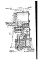
- Fig. 1 is a view in side elevation of the apparatus partly insection and partly broken away.
- Fig. 2 is a plan view partly in section of the entire apparatus.
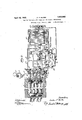
- Fig. 3 is a plan view of one end of the furnace showing the conduits for'carrying the heatedair to the gas burners. and furnace proper and also showing the heating coils.
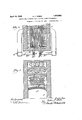
- Fig. 4 is an end view in section of the furnace showing the heating coils with air conduits and the vapor chamber.
- Fig. 5 is a plan view of one end of the furnace showing the air conduits connected with the conduit carrying the heated air to the furnace proper.
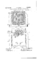
- Fig. 6 is an end view'of the furnace in section showing theair conduits and also the connection between the heating coils and the large coils.
- A-l is the furnace proper.
- A-2 is an arch in the furnace having positioned in it, holes marked A-3 through which the heat and gases of combustion pass.
- A-4 is aflue opening into heat interchanging chamber A-5'which connects with flue breeching A-6, which connects with flue blower A-7 and with stack A-8.
- B are the heating coils which, by means of pipe B-1, manifold B-2, expansion joints 13-3, and pipes B-4 connect with vapor chambers 0 and leading from these chambers are vapor lines 0-1, connecting with manifold 0-2 which connects, by means of pipe 0-3 to header 0-4 which header is connected by means of tubes 0-5 to header C-6 and out of which header extends pipe 0-7 which connects with coil 0-8, positioned in the water tank 0-9.
- Coil 0-8 is connected by means of pipe 0-9 to manifold 0-10 to receivers 0-11 and 0-12.
- header 0-4 Out of the bottom of header 0-4 extends line 0-13 and connects with manifold (1-14 which connects by means of pipe 015 to header 0-16 and this header is connected with pump D.
- Extending from the vapor chambers are pipes E with expansion swings E-l connecting to manifold 0-14.
- F is the supply line to tank F-1 through float controlled valve F-2 and from this tank eX- tends line F-B to manifold 0-16.
- G is the discharge from the pump D to the coils B having on it expansion joint G-l.
- G-2 is a by-pass around the pump D.
- H are lines extending from the bottom of the vapor chamber to manifold 1-1-1 and having expansion joints 11-2.
- This manifold 11-1 is connected by means of pipe 11-3 to water cooled coil 11-4 positioned in tank 11-5, and the said coil is connected by line 11-6 to tank 11-7.
- Throughfloat valve 11-8 the tank 11-7 has discharge to line 11-9.
- From tanks F-l and 1-1-7 is gas line J, connecting manifold 0-10.
- K are the hot air conduits having baffle plates K-l in them and connected with header K-2 having branches K-3 and K-4 extending down to the furnace through tunnel K-5 having branches K-6 and K-7 to gas burners K-9 and K-10.
- H-10 is a by-pass around the water cooling coil 11-4.
- 1, 2, 3, 4, 5, and 6 are liquid level gauges. 7, 8, 9, 10 and 11 are pressure gauges.
- 12 and 13 are manhole heads.
- 14 is a pressure relief valve.
- 15 is an expansion sleeve.
- 16 and 17 are check valves.
- 18 are pump valves. 19, 20,21, 22, 23, 24, 25, 26, 27, 28, 29, 30, 81, 32 and
- L are bafi'le plates positioned in the vapor chambers.
- M are cable connections for pyrometers.
- N isa water overflow from tank 0-9 into tank 11-5.
- P are supports for the different parts of'the apparatus.
- the oil to be treated is forced by means of a pump or other means not shown, inward through line F through float valve F-2 opening whenever the oil in tank F-1 falls below the predetermined level and flowsfrom there through line F-3 continuously through check valve 16 into manifold 0-16 into pump D constantly operating and is discharged through check valve 17 through line G into heating coils B and into line B-1 and the manifold B-2 through lines B-4 into vapor chambers 0 and from said chambers flows through lines E through expansion joints E-l, into manifold 0-14 and back into manifold 0-16 and into the pump and then back through the system as described.
- Fire is placed in the furnace A-.1 and passes up through openings A-3 around the tubes B through flue A-4 through chamber A-5 and through breeching A-6.
- the air for supply in the furnace is drawn from the atmosphere through tubes K and as it passes through chamber A-5 the heat from the waste furnace gases, passing through chamber A-5 preheats this air in the tubes K and the heated air passes through manifold K-2 into branches K-3, K-4 into the furnace through tunnel K-5 and to the gas burners Pig-2 and K-lO through branches K-6 and
- the vapors liberated in the chambers 0 pass up through vapor lines 0-1 into manifold 0-2 into header 0-4 through ipes 0-5 into header 0-6 through pipe 8-7, through water cooled coil 0-8 through manifold 0-10 and from there go into receivers 0-11 and 0-12 and are drawn off through valve 29 to any suitable storage, not shown, and the excess gas discharged through valve 28.
- the reflux condensate from the header 0-4 flows freelv through the line 0-13 into the header 0-14 where it mixes with lighter unvaporized oil from the chambers 0 and the mixture is introduced through the line 0-15 to the pump D and conveyed back to the cracking coil.
- the pipes E communicating with the vapor chambers 0 are so positioned that they withdraw the lighter residue from these chambers while the heavier carbon bearing substances are withdrawn through the pipes 11 for storage and subsequent use.
- the pressure in tanks F-1 and 11-7 is maintained uniform by means of line J connecting the incondensible gases under pressure with these tanks.
- the heavier unvaporized oil in the tubes 0 is drawn ofi' either continuously or intermittently through lines H, through expansion swings 1-1-2, into manifold 11-1, through line 11-3 through valve 21 through water cooled coil 1-1-4, through line 11-6, into tank 11-7.
- the oil can be dischargedinto tank 11-7 through line 11-3 without going through'the water cooled coil 11-4 by closing the valves 19 and 21 and opening valve 20, and passing the oil through line 11-10.
- the level of the oil in the tank H7 is controlled byfloat valve H-8 which opens'when the oil in tank H-7 rises above the predetermined level and the oil is discharged through line H 9, valve 25 to any desirable storage not shown.
- the temperature at which the oil is to be heated will vary approximately from 400.F. to 1200 F, more or less, although these limits are not absolute in either case. By this arrangement, a much hotter furnace temperature can be used in the furnace and a more economical fuel consumpti.on obtained.
- I clalm as my invention: 1. A. process for cracking oil, comprising raising the oil to a cracking heat while flowing through a coil located in a heating zone,
- a process for cracking oil comprising raising the oil to a cracking heat while flowing through a coil located in a heating zone
- a process for cracking oil comprising raising the oil to acracking heat while flowing through a coil located in a heating zone, in delivering the heated oil from the coil to an enlarged vapor chamber, wherein a predetermined liquid level is maintained, -in separately removing light unvaporized oil andheavy unvaporized oil from said vapor chamber, in assingvapors evolved from the oil to a deph egmator, in uniting reflux condensate separated from the vapors with the light unvaporized oil removed from said vapor chamber, in thereafter uniting said commingled reflux condensate and light unva orized oil.
- a process for cracking hydrocarbon oil comprising raising the oil to a cracking heat while flowing through a coil positionedin a heating zone, in delivering the heated oil from i the coil'to an enlarged vapor chamber, where in a predetermined liquid level is maintained, in removing heavy unvaporized oil from said vapor chamber, in passing vapors evolved f ,m the'oil to a dephlegmator, wherein inwith a quantity of fresh incoming charging oil for the process and in forcing the resulting commingled oils through said heating coil, to-be again admitted to said vapor chamher, in admitting heavy unvaporized oil removed from said vapor chamber to a zone apart from the vapor chamber, in which zone a liquid level is maintained, which is responsive to changes in the predetermined liquid level maintained in said vapor chamber, and from which zone the heavy unvaporized oil is automatically discharged, when the liquid level in the vapor chamber rises above the predetermined liquid. level desired to be maintained therein.
Description
April 12, 1 DUBBS 1,853,965" PROCESS FOR PRODUCING LOWER BOILING POINT HYDROCARBONS I Original Filed June 15, 920 4 shee tsksheei 1 April 12, 1932. I p. 3 DuBBs 1,853,965
PROCESS FOR PRODUCING LOWER BOILING POINT HYDROCARBONS I Original Filed June 15, 1920 4 Sheets-Sheet 2 A ril 12, 1932. c; p, Bs-
PROCESS FOR PRODUCING BOIIJING POINT HYDROCARBONS ori inal File dfiflneas, 1920 4 Sheets-Sheet 4 Patented-Apr. 12, 1932 Y UNITED STATES PATENT OFFICE CARBON P. DUBBS, OF WILMETTE, ILLINOIS, ASSIGNOR TO UNTVRSAL OIL PRODUCTS GOMPANY, OF CHICAGO, ILLINOIS, A CORPORATION OF SOUTH DAKOTA.
PROCESS FOR. raonocme LOWER BOILING rom'r mznnocamaons Continuation of application Serial No. 339,213, filed June 15, 1920, which is a division of application Serial No. 260,957, filed November 4, 1918. This application filed January 13, 1927. Serial No. 161,003.
This application is a continuation of application Serial No. 389,213, filed June 15th, 1920, which latter application constitutes a division of application Serial No. 260,957, filed November 4th, 1918.
' The objects of the invention are to provide a process for separating oils of diiferent boiling points; to provide a process wherein the oil under treatment is circulated through a coil and then to and from a vapor chamber which latter chamber is only partlyfilled with the oil, the oil being heated as it passes through the former coil and as it passes through the latter chamber and the oil being relieved-of more or less of its vapor content,
which vapors pass to and through a condenser while more or less of an insoluble material, such as carbon formed in the oil, settles and is drawn off while the remaining unvaporized oil passes from the larger chamber back to and through the heating tubes, the whole being maintained under pressure; to provide a process in which the heating of the oil under treatment is accomplished in the heating coils and said oil maintained in rapid circulation in these coils and then discharged into one end of the vapor chamber, said chamber being only partially filledwith the oil and the lighter portions of said oil withdrawn from said chamber at the other end forced back through the heating coil, while more or less of the oil and carbon and other solids are drawn ofi as residuum, said vapor chamber being of such size in the cross 1 section as to greatly reduce the speed of the flow of the oil from one end to the other and said chamber being of such dimensions as to permit more or less of its solid content to settle out and means being provided for the drawing ofi' of more or less of the solids that are thus settled out of the oil along with part of the oil and means provided for supplying fresh oil to the apparatus; to provide a process for continuous operation; to provide a process in which those products that are only partly reduced or converted to the desired low boiling point, are returned and further circulated through the heating'tubes in the larger chamber; to provide a process in which the vapors nothaving the desired low boiling points are condensed and automatically returned for further treatment; to provide a process whereby the free carbon produced can be settled out and removed without interrupting the operation of the still; to provide a process whereby any settlement of carbon on the heating tubes will be indicated before the particular part of the apparatus where such carbon settled is injured; to provide a process for controlling the rate of flow of the oil through the heating tubes by means of a pump or otherwise so as to more or less prevent the carbon and other solid matters from settling in such tubes; to provide a process for maintaining the oil in the heating tube under sufiicient flow as to maintain the small solid matters contained therein in suspension; to provide a process in which oil is automatically fed into the apparatus and removed therefrom and automatically maintained at a predetermined level in the larger tubes; to provide a process for passing the distillates from he reflux condenser into the heating coils; provide a process for reheating the fresh air -supplied to the urnace by utilizing the heat from the waste gases of said furnace; to provide in general a process of the character referred to.
In the drawings:
Fig. 1 is a view in side elevation of the apparatus partly insection and partly broken away. v
Fig. 2 is a plan view partly in section of the entire apparatus.
Fig. 3 is a plan view of one end of the furnace showing the conduits for'carrying the heatedair to the gas burners. and furnace proper and also showing the heating coils.
Fig. 4 is an end view in section of the furnace showing the heating coils with air conduits and the vapor chamber.
Fig. 5 is a plan view of one end of the furnace showing the air conduits connected with the conduit carrying the heated air to the furnace proper.
Fig. 6 is an end view'of the furnace in section showing theair conduits and also the connection between the heating coils and the large coils.
Referring to the drawings, A-l is the furnace proper. A-2 is an arch in the furnace having positioned in it, holes marked A-3 through which the heat and gases of combustion pass. A-4 is aflue opening into heat interchanging chamber A-5'which connects with flue breeching A-6, which connects with flue blower A-7 and with stack A-8. B are the heating coils which, by means of pipe B-1, manifold B-2, expansion joints 13-3, and pipes B-4 connect with vapor chambers 0 and leading from these chambers are vapor lines 0-1, connecting with manifold 0-2 which connects, by means of pipe 0-3 to header 0-4 which header is connected by means of tubes 0-5 to header C-6 and out of which header extends pipe 0-7 which connects with coil 0-8, positioned in the water tank 0-9. Coil 0-8 is connected by means of pipe 0-9 to manifold 0-10 to receivers 0-11 and 0-12. Out of the bottom of header 0-4 extends line 0-13 and connects with manifold (1-14 which connects by means of pipe 015 to header 0-16 and this header is connected with pump D. Extending from the vapor chambers are pipes E with expansion swings E-l connecting to manifold 0-14. F is the supply line to tank F-1 through float controlled valve F-2 and from this tank eX- tends line F-B to manifold 0-16. G is the discharge from the pump D to the coils B having on it expansion joint G-l. G-2 is a by-pass around the pump D. H are lines extending from the bottom of the vapor chamber to manifold 1-1-1 and having expansion joints 11-2. This manifold 11-1 is connected by means of pipe 11-3 to water cooled coil 11-4 positioned in tank 11-5, and the said coil is connected by line 11-6 to tank 11-7. Throughfloat valve 11-8 the tank 11-7 has discharge to line 11-9. From tanks F-l and 1-1-7 is gas line J, connecting manifold 0-10. K are the hot air conduits having baffle plates K-l in them and connected with header K-2 having branches K-3 and K-4 extending down to the furnace through tunnel K-5 having branches K-6 and K-7 to gas burners K-9 and K-10. H-10 is a by-pass around the water cooling coil 11-4. 1, 2, 3, 4, 5, and 6 are liquid level gauges. 7, 8, 9, 10 and 11 are pressure gauges. 12 and 13 are manhole heads. 14 is a pressure relief valve. 15 is an expansion sleeve. 16 and 17 are check valves. 18 are pump valves. 19, 20,21, 22, 23, 24, 25, 26, 27, 28, 29, 30, 81, 32 and 33 are valves.
L are bafi'le plates positioned in the vapor chambers. M are cable connections for pyrometers. N isa water overflow from tank 0-9 into tank 11-5. P are supports for the different parts of'the apparatus.
Describing now the operation of the process, the oil to be treated is forced by means of a pump or other means not shown, inward through line F through float valve F-2 opening whenever the oil in tank F-1 falls below the predetermined level and flowsfrom there through line F-3 continuously through check valve 16 into manifold 0-16 into pump D constantly operating and is discharged through check valve 17 through line G into heating coils B and into line B-1 and the manifold B-2 through lines B-4 into vapor chambers 0 and from said chambers flows through lines E through expansion joints E-l, into manifold 0-14 and back into manifold 0-16 and into the pump and then back through the system as described. Fire is placed in the furnace A-.1 and passes up through openings A-3 around the tubes B through flue A-4 through chamber A-5 and through breeching A-6. The air for supply in the furnace is drawn from the atmosphere through tubes K and as it passes through chamber A-5 the heat from the waste furnace gases, passing through chamber A-5 preheats this air in the tubes K and the heated air passes through manifold K-2 into branches K-3, K-4 into the furnace through tunnel K-5 and to the gas burners Pig-2 and K-lO through branches K-6 and The vapors liberated in the chambers 0 pass up through vapor lines 0-1 into manifold 0-2 into header 0-4 through ipes 0-5 into header 0-6 through pipe 8-7, through water cooled coil 0-8 through manifold 0-10 and from there go into receivers 0-11 and 0-12 and are drawn off through valve 29 to any suitable storage, not shown, and the excess gas discharged through valve 28. The reflux condensate from the header 0-4 flows freelv through the line 0-13 into the header 0-14 where it mixes with lighter unvaporized oil from the chambers 0 and the mixture is introduced through the line 0-15 to the pump D and conveyed back to the cracking coil. The pipes E communicating with the vapor chambers 0 are so positioned that they withdraw the lighter residue from these chambers while the heavier carbon bearing substances are withdrawn through the pipes 11 for storage and subsequent use.
The pressure in tanks F-1 and 11-7 is maintained uniform by means of line J connecting the incondensible gases under pressure with these tanks. The heavier unvaporized oil in the tubes 0 is drawn ofi' either continuously or intermittently through lines H, through expansion swings 1-1-2, into manifold 11-1, through line 11-3 through valve 21 through water cooled coil 1-1-4, through line 11-6, into tank 11-7. The oil can be dischargedinto tank 11-7 through line 11-3 without going through'the water cooled coil 11-4 by closing the valves 19 and 21 and opening valve 20, and passing the oil through line 11-10. The level of the oil in the tank H7 is controlled byfloat valve H-8 which opens'when the oil in tank H-7 rises above the predetermined level and the oil is discharged through line H 9, valve 25 to any desirable storage not shown.
It will readily be seenthat this arrangement provides for a continuous operation,
7 for the automatic maintenance of a definite level of liquid in the vapor chamber. The automatic utilization of the waste heat in the flue gases, the automatic control of the residuum withdrawn from the apparatus, means for circulation by convection without the use of the pump, the return of the reflux distilamount distilled ofi, the character of the oil being treated, etc., and the temperature used inthe furnace, these factors'having a bearing on the amount of solid material contained in the oil such as carbon, and the amount of agitation or velocity necessary to maintain same in suspension in the heating coils will vary. The entire system is subjected to a pressure either vapor'or gas or otherwise created which pressure will range from 50 to 500 pounds per square inch more or less, with pressure unit varying in accordance with conditions to be met.
The temperature at which the oil is to be heated will vary approximately from 400.F. to 1200 F, more or less, although these limits are not absolute in either case. By this arrangement, a much hotter furnace temperature can be used in the furnace and a more economical fuel consumpti.on obtained.
I clalm as my invention: 1. A. process for cracking oil, comprising raising the oil to a cracking heat while flowing through a coil located in a heating zone,
in delivering the heated oil from the coil to an enlarged va or chamber, wherein a predetermined liquldlevel is maintained, in separatelyremoving light unvaporized oil and heavy unvaporized'oil from said vapor chamber, in passing vapors evolved from theoil incoming charging stock, in supplying the resulting mixture to said heating coil, in maintaining a predetermined body of the heavy unvaporized oil removed from said vapor chamber in a zone apart from the vapor chamber, and in controlling the removal of heavy unvaporized oil from said vapor.
chamberby variations in the volume of oil in sa1d zone.
-maintained therein.
2. A process for cracking oil, comprising raising the oil to a cracking heat while flowing through a coil located in a heating zone,
in delivering the heated oil from the coil to an enlarged vapor chamber, wherein apreletermined liquid level is maintained, in eparately removing light unvaporized oil and-heavy unvaporized oil from said vapor chamber, in passing vapors evolved from the oil to a dephlegmator, in uniting reflux condensate separated from the vapors with the light unvaporized oil removed from said vapor chamber, in thereafter uniting, said commingled reflux condensate and light unvaporized oil with a regulated quantity of fresh incoming,charging stock, in supplying the resulting mixture to said heating coil, in admitting heavy unvaporized oil removed from said vapor chamber to a zone apart from the vapor chamber, in which zone a liquid level is maintained, which is responsive to changes in the predetermined liquid level maintained in said vapor chamber, and from which zone the heavy unvaporized oil is automatically discharged, when the liquid level in the vapor chamber rises above the predetermined liquid level desired to be 3. A process for cracking oil, comprising raising the oil to acracking heat while flowing through a coil located in a heating zone, in delivering the heated oil from the coil to an enlarged vapor chamber, wherein a predetermined liquid level is maintained, -in separately removing light unvaporized oil andheavy unvaporized oil from said vapor chamber, in assingvapors evolved from the oil to a deph egmator, in uniting reflux condensate separated from the vapors with the light unvaporized oil removed from said vapor chamber, in thereafter uniting said commingled reflux condensate and light unva orized oil. with a regulated quantity of fres incoming charging stock, in supplying the resulting mixture to said heating coil, in maintaining a volume of the heavy unvaporized oil removed from' said vapor chamber under the same ressure' as that prevailing in the vapor cham er, in a zone apart from the vapor chamber, and in controlling the removal of heavy unvaporized oil from said vapor chamher by variations in the volume of oil in said zone.
4. A process for cracking hydrocarbon oil, comprising raising the oil to a cracking heat while flowing through a coil positionedin a heating zone, in delivering the heated oil from i the coil'to an enlarged vapor chamber, where in a predetermined liquid level is maintained, in removing heavy unvaporized oil from said vapor chamber, in passing vapors evolved f ,m the'oil to a dephlegmator, wherein inwith a quantity of fresh incoming charging oil for the process and in forcing the resulting commingled oils through said heating coil, to-be again admitted to said vapor chamher, in admitting heavy unvaporized oil removed from said vapor chamber to a zone apart from the vapor chamber, in which zone a liquid level is maintained, which is responsive to changes in the predetermined liquid level maintained in said vapor chamber, and from which zone the heavy unvaporized oil is automatically discharged, when the liquid level in the vapor chamber rises above the predetermined liquid. level desired to be maintained therein.
CARBON P. DUBBS.
Priority Applications (1)
| Application Number | Priority Date | Filing Date | Title |
|---|---|---|---|
| US161003A US1853965A (en) | 1927-01-13 | 1927-01-13 | Process for producing lower boiling point hydrocarbons |
Applications Claiming Priority (1)
| Application Number | Priority Date | Filing Date | Title |
|---|---|---|---|
| US161003A US1853965A (en) | 1927-01-13 | 1927-01-13 | Process for producing lower boiling point hydrocarbons |
Publications (1)
| Publication Number | Publication Date |
|---|---|
| US1853965A true US1853965A (en) | 1932-04-12 |
Family
ID=22579387
Family Applications (1)
| Application Number | Title | Priority Date | Filing Date |
|---|---|---|---|
| US161003A Expired - Lifetime US1853965A (en) | 1927-01-13 | 1927-01-13 | Process for producing lower boiling point hydrocarbons |
Country Status (1)
| Country | Link |
|---|---|
| US (1) | US1853965A (en) |
-
1927
- 1927-01-13 US US161003A patent/US1853965A/en not_active Expired - Lifetime
Similar Documents
| Publication | Publication Date | Title |
|---|---|---|
| US1853965A (en) | Process for producing lower boiling point hydrocarbons | |
| US1783185A (en) | Apparatus for producing lower-boiling-point hydrocarbons | |
| US2675126A (en) | Apparatus for separating oil from water | |
| US1674827A (en) | Process and apparatus for cracking oil | |
| US1869626A (en) | Method and means for the control of heat in the distillation of oil | |
| US1686654A (en) | Method for treating hydrocarbon oils | |
| US1965335A (en) | Process and apparatus for cracking hydrocarbon oils | |
| US1610594A (en) | Apparatus for distilling hydrocarbons | |
| US1561169A (en) | Hydrocarbon distillation | |
| US1753769A (en) | Process and apparatus for treating petroleum oil | |
| US1782686A (en) | Process for cracking hydrocarbon oil | |
| US1839010A (en) | Apparatus for treating oils | |
| US1685476A (en) | of chicago | |
| US1835765A (en) | Apparatus for cracking hydrocarbon oils | |
| US1541553A (en) | Apparatus for treating oil | |
| US1163570A (en) | Process of and apparatus for distilling petroleum. | |
| US1923016A (en) | Process and apparatus for treating hydrocarbons | |
| US1852748A (en) | Process and apparatus for treating hydrocarbons | |
| US1547993A (en) | Pressure still | |
| US1259786A (en) | Apparatus for the treatment of hydrocarbon oils. | |
| US1576564A (en) | Apparatus for distilling hydrocarbons | |
| US1998402A (en) | Apparatus for cracking oil | |
| US1788947A (en) | Apparatus for distilling oil | |
| US1582585A (en) | Apparatus for treating hydrocarbon oils | |
| US1800436A (en) | Process and apparatus for treating petroleum hydrocarbons |