US1853945A - Thread protector - Google Patents
Thread protector Download PDFInfo
- Publication number
- US1853945A US1853945A US480743A US48074330A US1853945A US 1853945 A US1853945 A US 1853945A US 480743 A US480743 A US 480743A US 48074330 A US48074330 A US 48074330A US 1853945 A US1853945 A US 1853945A
- Authority
- US
- United States
- Prior art keywords
- protector
- threads
- sleeve
- pipe
- thread protector
- Prior art date
- Legal status (The legal status is an assumption and is not a legal conclusion. Google has not performed a legal analysis and makes no representation as to the accuracy of the status listed.)
- Expired - Lifetime
Links
Images
Classifications
-
- F—MECHANICAL ENGINEERING; LIGHTING; HEATING; WEAPONS; BLASTING
- F16—ENGINEERING ELEMENTS AND UNITS; GENERAL MEASURES FOR PRODUCING AND MAINTAINING EFFECTIVE FUNCTIONING OF MACHINES OR INSTALLATIONS; THERMAL INSULATION IN GENERAL
- F16L—PIPES; JOINTS OR FITTINGS FOR PIPES; SUPPORTS FOR PIPES, CABLES OR PROTECTIVE TUBING; MEANS FOR THERMAL INSULATION IN GENERAL
- F16L57/00—Protection of pipes or objects of similar shape against external or internal damage or wear
- F16L57/005—Protection of pipes or objects of similar shape against external or internal damage or wear specially adapted for the ends of pipes
-
- B—PERFORMING OPERATIONS; TRANSPORTING
- B65—CONVEYING; PACKING; STORING; HANDLING THIN OR FILAMENTARY MATERIAL
- B65D—CONTAINERS FOR STORAGE OR TRANSPORT OF ARTICLES OR MATERIALS, e.g. BAGS, BARRELS, BOTTLES, BOXES, CANS, CARTONS, CRATES, DRUMS, JARS, TANKS, HOPPERS, FORWARDING CONTAINERS; ACCESSORIES, CLOSURES, OR FITTINGS THEREFOR; PACKAGING ELEMENTS; PACKAGES
- B65D59/00—Plugs, sleeves, caps, or like rigid or semi-rigid elements for protecting parts of articles or for bundling articles, e.g. protectors for screw-threads, end caps for tubes or for bundling rod-shaped articles
- B65D59/06—Caps
Definitions
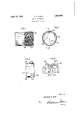
- FIG. 1 is an elevation of the end of a piece .of pipe on which is shown one form of thread protector, embodying my invent-ion, the protector being shown in section on line 11 of Fig. 2;
- r r I Fig. 2 is an elevation of the left hand end of the protector shownin Fig. 1;
- Fig. 3 is an axial section through the pro-' tee-tor
- Fig. 4 is a portion of Fig. 1 on an enlarged scale.
- the thread protector comprises a cup shaped sleeve 33, the internal diameter of which is slightly larger than theexternal diameter of the threads, and one end of which is slightly flattened at a plurality of points, as shown-at 34:, 35 and 36 in Fig. 2. While I have shown I in the drawings a protector having three such flattened portions, it will be understood that the sleeve may be formed with any desired number of flattened portions.
- the flattened portions 34, 35 and 36 are provided with intransit. 1
- the protector is-further provided with an outwardly flaring, mouth '38, which facilitates positioningv the protector on the pipe,and with an end flange j 39, which engages. the end 'ofthe pipe.
- This be-ad' makes the sleeve of the protector relatively rigid and inflexible, with the result that anundue amount of force must be exerted to push the protector tojits "proper position over the threads, or to re .move it from the pipe by either'straight axial movement or by unscrewing it therefrom.
- the absence of the continuous bead and the novel lug construction makes the sleeve ofthe present thread protector much more flexible than that of the protector described in the aforesaid patent, and therefore permits it to be more easily forced to its proper position over the threads and more readily unscrewed from the pipe than said protector.
- Claims 1 In combination; with a threaded element, a thread protector comprising a metal sleeve having at one end thereof an end wall engaging the end of the threaded element, the other end of said sleevevhaving spaced portions which are pressed radially inwardly, said spaced portions only being provided with inwardly projecting lugs for engaging the threads of said element.
- a protector for threaded elements comprising a. metal sleeve having a laterally extending wall portion at one end thereof, the other end of said sleeve having spaced portions which are pressed radially inwardly, said spaced portions only being provided Withinwardly projecting lugs for engagementwith the threads of said element.
- a protector for a threaded element comprising a metal sleeve having a laterally extending wall portion at one end thereof, and at its other end said sleeve having spaced radially flexible inwardly pressed portions, said spaced portions only being provided with inwardly projecting lugs for engagement with the threads of said element.
- a protector for a threaded element comprising a metal sleeve having means at one end thereof for engagement with the end of said element, and at its other endspaced portions lying at a shorter radial distance from the axis of said sleeve than the portions of said end intermediate said spaced portions, said spaced portions only having inwardly projecting lugs.
Description
April 12,1932. E 1,853,945
THREAD PROTECTOR Filed Sept. 9, 1930 F795 Fig 4 gmwnto'c Herman A. Unke I Patented Apr. 12, 1932 UNHTED STATES HERMAN A. 11mm, 01 CLEVELAND, oHIo Application filed September 9, 1930. Serial no. 456,743.
In my aforesaid patent, I have shown and described a thread protector that is very low in cost and which is adapted .to be readily placedin position over the threads and is not likely tobecome displaced while the pipe is being handled.
It is a primary object of the presentinvention to provide a thread protector which is vsomewhat similar to the protector shown in the aforesaid patent, but which is so formed that it may be made of lighter gauge sheet metal, more easily forced to its proper position over the threads and more easily'removed from the pipe or other threaded product than said protector. g
Other objects of the invention and the features of novelty will be apparent from the following description taken in connection with the accompanying drawings, wherein Fig. 1 is an elevation of the end of a piece .of pipe on which is shown one form of thread protector, embodying my invent-ion, the protector being shown in section on line 11 of Fig. 2; r r I Fig. 2 is an elevation of the left hand end of the protector shownin Fig. 1;
Fig. 3 is an axial section through the pro-' tee-tor, and
Fig. 4 is a portion of Fig. 1 on an enlarged scale. Referring now to the drawings in detail, the thread protector comprises a cup shaped sleeve 33, the internal diameter of which is slightly larger than theexternal diameter of the threads, and one end of which is slightly flattened at a plurality of points, as shown-at 34:, 35 and 36 in Fig. 2. While I have shown I in the drawings a protector having three such flattened portions, it will be understood that the sleeve may be formed with any desired number of flattened portions. The flattened portions 34, 35 and 36 are provided with intransit. 1
wardly projecting liigseflwhich are a hi 7 angular cross-section and have a gently sloping side 37a and a vertical side 37b,* hieh meet at an edge 370. The protector is-further provided with an outwardly flaring, mouth '38, which facilitates positioningv the protector on the pipe,and with an end flange j 39, which engages. the end 'ofthe pipe.
.When the sleeve is forced over the threads, 7
threads of. the pipe, while the vertical sides j 37 b ofthe lugs prevent the protector from being pulled off of the pipe by straight axial movement, but permits it tobe readily un screwed therefrom.
While the flattened end of the sleeve and theflange 39 do not make tight joints with the pipe, these connections. are sufficiently tlght to permit this form -of protector. to be ,used for protecting the threads in such coating operations as galvanizing. A slight amount of the galvanizing material will work into the space between the threads and the protector, but experience has shownthat the amount of the coating material that adheres V to the threads -isrelatively small, but issuflicient to prevent rusting during the time that the pipe is normally held in storage, or is'in As shown in my aforesaid patent, the sleeve of the protector is provided with a continuous bead of substantially semi-circular cross- 'section. This be-ad' makes the sleeve of the protector relatively rigid and inflexible, with the result that anundue amount of force must be exerted to push the protector tojits "proper position over the threads, or to re .move it from the pipe by either'straight axial movement or by unscrewing it therefrom. The absence of the continuous bead and the novel lug construction makes the sleeve ofthe present thread protector much more flexible than that of the protector described in the aforesaid patent, and therefore permits it to be more easily forced to its proper position over the threads and more readily unscrewed from the pipe than said protector.
While I have shown and described the preferred form of my invention, it will, of course, be understood thatI do not regard my invention as limited to the particular embodiment disclosed, since various changes 19 may be made therein without departing from the spirit of the invention and the scope of the appended claims.
Claims 1. In combination; with a threaded element, a thread protector comprising a metal sleeve having at one end thereof an end wall engaging the end of the threaded element, the other end of said sleevevhaving spaced portions which are pressed radially inwardly, said spaced portions only being provided with inwardly projecting lugs for engaging the threads of said element.
2. combination as set forth in claim 1, inwhich the lugs are of substantially triangular crossseotion. i
3, A protector for threaded elements comprising a. metal sleeve having a laterally extending wall portion at one end thereof, the other end of said sleeve having spaced portions which are pressed radially inwardly, said spaced portions only being provided Withinwardly projecting lugs for engagementwith the threads of said element.
4.- A protector as defined in claim 3, in which the lugs are of substantially triangular cross-section.
5. A protector for a threaded element, comprising a metal sleeve having a laterally extending wall portion at one end thereof, and at its other end said sleeve having spaced radially flexible inwardly pressed portions, said spaced portions only being provided with inwardly projecting lugs for engagement with the threads of said element.
6.- A protector as defined in claim 5, in which the lugs are of substantially triangular cross-section. l
7. A protector for a threaded element, comprising a metal sleeve having means at one end thereof for engagement with the end of said element, and at its other endspaced portions lying at a shorter radial distance from the axis of said sleeve than the portions of said end intermediate said spaced portions, said spaced portions only having inwardly projecting lugs.
8. A protector as defined in claim 7, in which the lugs are of substantially triangular cross-section.
In testimony whereof I affix my signature.
HERMAN A. UNKE.
Priority Applications (1)
| Application Number | Priority Date | Filing Date | Title |
|---|---|---|---|
| US480743A US1853945A (en) | 1930-09-09 | 1930-09-09 | Thread protector |
Applications Claiming Priority (1)
| Application Number | Priority Date | Filing Date | Title |
|---|---|---|---|
| US480743A US1853945A (en) | 1930-09-09 | 1930-09-09 | Thread protector |
Publications (1)
| Publication Number | Publication Date |
|---|---|
| US1853945A true US1853945A (en) | 1932-04-12 |
Family
ID=23909180
Family Applications (1)
| Application Number | Title | Priority Date | Filing Date |
|---|---|---|---|
| US480743A Expired - Lifetime US1853945A (en) | 1930-09-09 | 1930-09-09 | Thread protector |
Country Status (1)
| Country | Link |
|---|---|
| US (1) | US1853945A (en) |
Cited By (6)
| Publication number | Priority date | Publication date | Assignee | Title |
|---|---|---|---|---|
| US3094147A (en) * | 1961-03-22 | 1963-06-18 | Internat Metal Hose Company | Bendable tubing |
| US3785682A (en) * | 1970-11-17 | 1974-01-15 | Advanced Drainage Syst Inc | Flexible fittings for corrugated tubing |
| FR2547532A1 (en) * | 1983-06-15 | 1984-12-21 | Lhomme Sa | METHOD FOR MANUFACTURING A HOLLOW BODY OF CARTON, OF MEDIUM DECREASING DIAMETER, HOLLOW BODY THUS OBTAINED AND USE THEREOF |
| EP0152776A2 (en) * | 1984-02-21 | 1985-08-28 | REHAU AG + Co | Pot-shaped plastic sealing cap for pipes |
| WO2010015484A1 (en) * | 2008-08-05 | 2010-02-11 | Vallourec Mannesmann Oil & Gas France | Device for protecting a threaded tubular component and tubular component provided with the device |
| US11274466B2 (en) * | 2018-06-25 | 2022-03-15 | Mat Holdings, Inc. | Post and cap for chain link fence with enhanced engagement |
-
1930
- 1930-09-09 US US480743A patent/US1853945A/en not_active Expired - Lifetime
Cited By (15)
| Publication number | Priority date | Publication date | Assignee | Title |
|---|---|---|---|---|
| US3094147A (en) * | 1961-03-22 | 1963-06-18 | Internat Metal Hose Company | Bendable tubing |
| US3785682A (en) * | 1970-11-17 | 1974-01-15 | Advanced Drainage Syst Inc | Flexible fittings for corrugated tubing |
| US4693919A (en) * | 1983-06-15 | 1987-09-15 | Lhomme S.A. | Protective device and method for forming protective device and use of protective device as a package and apparatus for forming protective device |
| EP0130870A1 (en) * | 1983-06-15 | 1985-01-09 | Lhomme Sa | Method of making a hollow cardboard body with decreasing middle diameter, hollow body so obtained and its use |
| FR2547532A1 (en) * | 1983-06-15 | 1984-12-21 | Lhomme Sa | METHOD FOR MANUFACTURING A HOLLOW BODY OF CARTON, OF MEDIUM DECREASING DIAMETER, HOLLOW BODY THUS OBTAINED AND USE THEREOF |
| EP0152776A2 (en) * | 1984-02-21 | 1985-08-28 | REHAU AG + Co | Pot-shaped plastic sealing cap for pipes |
| EP0152776A3 (en) * | 1984-02-21 | 1986-05-21 | Rehau Ag + Co | Pot-shaped plastic sealing cap for pipes |
| WO2010015484A1 (en) * | 2008-08-05 | 2010-02-11 | Vallourec Mannesmann Oil & Gas France | Device for protecting a threaded tubular component and tubular component provided with the device |
| FR2934884A1 (en) * | 2008-08-05 | 2010-02-12 | Vallourec Mannesmann Oil & Gas | METHOD AND DEVICE FOR PROTECTING A THREADED TUBULAR COMPONENT AND TUBULAR COMPONENT PROVIDED WITH THE DEVICE |
| US20110203698A1 (en) * | 2008-08-05 | 2011-08-25 | Vallourec Mannesmann Oil & Gas France | Device for protecting a threaded tubular component and tubular component provided with the device |
| JP2011530052A (en) * | 2008-08-05 | 2011-12-15 | バローレック・マネスマン・オイル・アンド・ガス・フランス | Protective device for threaded circular tubular member and circular tubular member with protective device |
| CN102112794B (en) * | 2008-08-05 | 2013-02-06 | 法国瓦罗里克.曼尼斯曼油汽公司 | Device for protecting threaded tubular component and tubular component provided with same |
| US8813790B2 (en) | 2008-08-05 | 2014-08-26 | Vallourec Oil And Gas France | Device for protecting a threaded tubular component and tubular component provided with the device |
| US11274466B2 (en) * | 2018-06-25 | 2022-03-15 | Mat Holdings, Inc. | Post and cap for chain link fence with enhanced engagement |
| US11913246B2 (en) | 2018-06-25 | 2024-02-27 | Mat Holdings, Inc. | Post and cap for chain link fence with enhanced engagement |
Similar Documents
| Publication | Publication Date | Title |
|---|---|---|
| US2021745A (en) | Threaded follower pipe joint or fitting | |
| US1837345A (en) | Closure for cylindrical members | |
| US2437632A (en) | Coupling for tubes | |
| US2179127A (en) | Pipe coupling | |
| US2258528A (en) | Pipe union | |
| US1934681A (en) | Pipe end protector | |
| US1738915A (en) | Pipe coupling | |
| US2207176A (en) | Fluid can with resilient spout | |
| US1853945A (en) | Thread protector | |
| US1551381A (en) | Apolis | |
| US2062145A (en) | Pipe fitting | |
| US2327656A (en) | Container | |
| US1771522A (en) | Thread-protecting closure | |
| US2471716A (en) | Barrel sput | |
| US3239252A (en) | Conduit fitting | |
| US2459609A (en) | Coupling for tubes | |
| US1941235A (en) | Thread protector | |
| US1980364A (en) | Pipe protector | |
| US1644154A (en) | Bushing for metal receptacles | |
| US1783893A (en) | Pipe-end protector | |
| US2008245A (en) | Plug flange for barrel heads | |
| US2336139A (en) | Hose clamp | |
| US1853944A (en) | Protector | |
| US1819243A (en) | Hose connection | |
| US2043339A (en) | Fluid container |