US185391A - Improvement in car-starters - Google Patents
Improvement in car-starters Download PDFInfo
- Publication number
- US185391A US185391A US185391DA US185391A US 185391 A US185391 A US 185391A US 185391D A US185391D A US 185391DA US 185391 A US185391 A US 185391A
- Authority
- US
- United States
- Prior art keywords
- car
- spring
- drum
- wheel
- hub
- Prior art date
- Legal status (The legal status is an assumption and is not a legal conclusion. Google has not performed a legal analysis and makes no representation as to the accuracy of the status listed.)
- Expired - Lifetime
Links
- 239000007858 starting material Substances 0.000 title description 8
- 240000001973 Ficus microcarpa Species 0.000 description 6
- 238000010276 construction Methods 0.000 description 4
- 230000000994 depressed Effects 0.000 description 2
- 230000000881 depressing Effects 0.000 description 2
Images
Classifications
-
- B—PERFORMING OPERATIONS; TRANSPORTING
- B60—VEHICLES IN GENERAL
- B60T—VEHICLE BRAKE CONTROL SYSTEMS OR PARTS THEREOF; BRAKE CONTROL SYSTEMS OR PARTS THEREOF, IN GENERAL; ARRANGEMENT OF BRAKING ELEMENTS ON VEHICLES IN GENERAL; PORTABLE DEVICES FOR PREVENTING UNWANTED MOVEMENT OF VEHICLES; VEHICLE MODIFICATIONS TO FACILITATE COOLING OF BRAKES
- B60T7/00—Brake-action initiating means
- B60T7/12—Brake-action initiating means for automatic initiation; for initiation not subject to will of driver or passenger
- B60T7/128—Self-acting brakes of different types for railway vehicles
Definitions
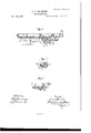
- FIG. 1 is a plan representing the frame of the lower portion of a car with its runninggear.
- Fig. 2 is a side elevation of the same.
- Fig. 3 is a transverse section on the line fw w of Fig. l.
- Fig. 4 is a longitudinal section on the line x a: of Fig. l.
- Fig. 5 is a longitudinal section on the line y y of Fig. l.
- Fig. 6 is a transverse section on the line z z of Fig. l.
- My invention relates to certain improvements in car-starters; and consists in a mechanism of peculiar construction for compressing a spring, the force of which, when released, is utilized in starting the car, the spring, while being compressed, serving to retard the inotion of the wheels, and performing the office ofa brake; and my invention also consists in a certain device connected with a crank at each end of the car, for operating the shipper, by which the mechanism for compressing the spring and utilizing its force for starting vthe car is thrown in and out of action; and my invention also consists in a ratchet-wheel on the windingdrum,in combination with a pawl operated by a spring foot-piece, to hold the mainspring while the clutches are being shifted, in order that the spring may be employed in starting the car, the raising of the pawl by the depression of the foot-piece allowing the mainspring to be liberated.
- a chain, lo which is led through a horizontal tube, B, secured to the frame A, the other end of the chain being fastened to a pin passing through longitudinal slots l, formed in the tube diametrically opposite each other, the pin projecting out beyond the sides of the tube, so as to form a stop for one end of a spiral spring, m, wound around the tube, by which construction, when the chain is wound around the drum P, the spring m will be compressed, as desired.
- R is a rack on the upper side of the bar Q, with which engages a pinion, r, on a horizontal shaft, s, extending longitudinally from one end of the car to the other, each end of the shaft being provided with a bevel-gear, t, with which engages another bevel-gear, u, on the lower end of a v ertical shaft, S, provided at its upper end with a crank or handle, c, by turning which the driver can operate the friction-clutches, so as to cause the drum P to be rotated by eith er one, as desired, according to the direction iii which the car is going, the arrangement of gearing described causing the conical hubs ot the friction-clutches to be revolved in opposite directions, so that either clutch may be used to revolve the drum and wind up the chain, as is necessary for a car intended to travel in either direction.
- One of the flanges, 8, of the drum P is provided with ratchet-teeth, with which engages a pawl, 9, kept in contact therewith by means of a spring, 1l, the object of the paWl being to prevent the revolution of the ⁇ drum and the release of the spring during the shifting of the friction-clutches, for a purpose to be presently described.
- the pawl is raised to release the drum P by a cam, 12, depressing its tail, 13, the cam being operated by a spring foot-piece, 14, intended to be A placed at each end of the car.
- the driver turns the handle or crank c in a direction contrary to the arrow 16, which uncouples the Wheel N from its hub L, and couples the Wheel M with its hub K, the pa-Wl during this operation preventing the drum from being revolved by the recoil of the spring m.
- the piece 14 is depressed by the foot of the driver, which raises the pawl 9out of the teeth of the ratchetwheel 8, and releases the spring m, the accumulated force of which revolves the drum, and
- the driver operates the shipper, so as to first couple the wheel M with the hub K, in order to compress the spring m, the power resulting from the recoil of which being transmitted, through the drum P, wheel N, hub L, and gearsh e I, to the axle C and wheels E, to be utilized in starting the car, as before described.
- the drum P with its ratchet-wheel 8 and pawl 9, chain k, and spring m, and the frictionclutches M K and N L on the shaft d, in conibination with the gearing H c and I e h, axle C, and car-Wheels E, all constructed and operating substantially in the manner and for the purpose set forth.
Description
ZSheetsv-Sheetl.
J. T. CROOKER.
CAR-STARTER. f NO 185,391. Patented Dec. 19, 1876.
'rn-1E GHAPmc caux 2 Sheets-Sheet Z.
J. T. CROOKER.
CAR-STARTER.
Patented Dec. 19, 1876.
THE GRAPHIC CDAILY ENT OFFICEo JAMES T. GROOKER, OF BOSTON, ASSIGNOR TO HIMSELF AND ALDIS L. WAITE, LAWRENCE, MASSACHUSETTS.
IMPROVEMENT IN C-AR-STARTERS.
Specification forming part of Lettere Patent No. 185,391, dated December 19, 1876; application tiled July 31, 1876.
To all whom it may concern:
Be it known that I, JAMES T. OROOKER, of Boston, in the county of Suffolk and State of Massachusetts, have invented certain Improvements in Gar-Starters, of which the following is a full, clear, and exact description, reference being had to the accompanying drawings, making part of this specification, in which` Figure 1 is a plan representing the frame of the lower portion of a car with its runninggear. Fig. 2 is a side elevation of the same. Fig. 3 is a transverse section on the line fw w of Fig. l. Fig. 4 is a longitudinal section on the line x a: of Fig. l. Fig. 5 is a longitudinal section on the line y y of Fig. l. Fig. 6 is a transverse section on the line z z of Fig. l.
My invention relates to certain improvements in car-starters; and consists in a mechanism of peculiar construction for compressing a spring, the force of which, when released, is utilized in starting the car, the spring, while being compressed, serving to retard the inotion of the wheels, and performing the office ofa brake; and my invention also consists in a certain device connected with a crank at each end of the car, for operating the shipper, by which the mechanism for compressing the spring and utilizing its force for starting vthe car is thrown in and out of action; and my invention also consists in a ratchet-wheel on the windingdrum,in combination with a pawl operated by a spring foot-piece, to hold the mainspring while the clutches are being shifted, in order that the spring may be employed in starting the car, the raising of the pawl by the depression of the foot-piece allowing the mainspring to be liberated.
To enable others skilled in the art to understand and use my invention I will proceed to describe the manner in whichA I have carried it out.
In the said drawings,Arepresents the frame of the lower portion of the car, to which are secured the housings of the boxes a of the axles C D of the wheels E G. Inside a frame, b, connecting the axles C D, and upon the axle C, are secured two gears, H I, one, H, engaging with a gear, c, on a conical hub, K, which revolves on a stationary shaft, d, the ends of which are secured in the frame b, the other gear, I, engaging with an intermediate gear, e, on a stud projecting inside of the frame b, this latter gear e engaging with another gear, h, oii another conical hub, L, also revolving on the stationary shaft d. The conical hubs t into correspondingly-shaped seats formed in the outer sides of wheels M N, which revolve on the shaft d, two friction-clutches being thus formed. These wheels M N are connected by horizontal rodsi, which pass through a flanged drum, P, and thus couple it therewith, so that the wheels and drum will revolve together. To the periphery of the drum P is secured one end of a chain, lo, which is led through a horizontal tube, B, secured to the frame A, the other end of the chain being fastened to a pin passing through longitudinal slots l, formed in the tube diametrically opposite each other, the pin projecting out beyond the sides of the tube, so as to form a stop for one end of a spiral spring, m, wound around the tube, by which construction, when the chain is wound around the drum P, the spring m will be compressed, as desired. From a bar, Q, sliding transversely in guides n, ex tending down from the frame-Work A,.pro ]ect two shipper-arms, 11 q, which bear against the inner faces of the wheels M N, and serve t0 force them over their respective conical hubs K L, the movement of the bar Q in one direction serving to couple the wheel M with its hub K, and simultaneously uncouple the wheel N from its hub L, and vice versa.
The movement of the bar is accomplished in the following manner: R is a rack on the upper side of the bar Q, with which engages a pinion, r, on a horizontal shaft, s, extending longitudinally from one end of the car to the other, each end of the shaft being provided with a bevel-gear, t, with which engages another bevel-gear, u, on the lower end of a v ertical shaft, S, provided at its upper end with a crank or handle, c, by turning which the driver can operate the friction-clutches, so as to cause the drum P to be rotated by eith er one, as desired, according to the direction iii which the car is going, the arrangement of gearing described causing the conical hubs ot the friction-clutches to be revolved in opposite directions, so that either clutch may be used to revolve the drum and wind up the chain, as is necessary for a car intended to travel in either direction. One of the flanges, 8, of the drum P is provided with ratchet-teeth, with which engages a pawl, 9, kept in contact therewith by means of a spring, 1l, the object of the paWl being to prevent the revolution of the `drum and the release of the spring during the shifting of the friction-clutches, for a purpose to be presently described. The pawl is raised to release the drum P by a cam, 12, depressing its tail, 13, the cam being operated by a spring foot-piece, 14, intended to be A placed at each end of the car.
Operation: When the car is moving in the direction of the arrow 15, Fig. 1, and it is desired to stop, the driver turns the handle or crank v in the direction ofthe arrow 16, which, through the connections above described, couples the wheel N with its hub L, and at the same time uncouples the wheel M from its hub K. The Wheel N is then revolved by the gears I e h, and With it the drum P, which causes the chain 7c to be Wound thereon and the mainsprin g m to be compressed, the resistance of which retards, and nally stops, the revolution of the wheels E E, the spring thus performing the office of a brake, and the power of the spring is gradually vcollected and held by lthe pawl dropping over the teeth of ratchetwheel 8. As soon as the car stops, the driver turns the handle or crank c in a direction contrary to the arrow 16, which uncouples the Wheel N from its hub L, and couples the Wheel M with its hub K, the pa-Wl during this operation preventing the drum from being revolved by the recoil of the spring m. When it is desired to start the car, the piece 14 is depressed by the foot of the driver, which raises the pawl 9out of the teeth of the ratchetwheel 8, and releases the spring m, the accumulated force of which revolves the drum, and
communicates motion, through the wheel M, hub K, and gears c H, to the axle C, causing the wheels E to be turned in the same direction they were previously moving to start the car forward, the strain upon the horses and wear of the parts incident to the sudden starting of the car being thereby avoided. When the car is traveling in the direction contrary to the arrowvl, the driver operates the shipper, so as to first couple the wheel M with the hub K, in order to compress the spring m, the power resulting from the recoil of which being transmitted, through the drum P, wheel N, hub L, and gearsh e I, to the axle C and wheels E, to be utilized in starting the car, as before described.
What I claim as my invention, and desire to secure by Letters Patent, is-
1. The drum P, with its ratchet-wheel 8 and pawl 9, chain k, and spring m, and the frictionclutches M K and N L on the shaft d, in conibination with the gearing H c and I e h, axle C, and car-Wheels E, all constructed and operating substantially in the manner and for the purpose set forth.
2. The bar Q, with its rack R and shipperarms p g, for operating the clutches, in combination with the horizontal shaft s, with its pinion r and bevel-gears t, and the vertical shafts S, with their cranks v and bevel-gears u, operating substantially as described.
3. In combination with the drum P, ratchetwheel 8, and pawl 9, a mechanism to be operated by the foot, for raising the pawl and releasing the spring m, substantially as and for the purpose set forth.
Witness my hand this 27th day of July, A. D. 1876.
` JAMES T. GROOKER. In presence of N. W. STEARNS, W. J. CAMBRIDGE.
Publications (1)
| Publication Number | Publication Date |
|---|---|
| US185391A true US185391A (en) | 1876-12-19 |
Family
ID=2254797
Family Applications (1)
| Application Number | Title | Priority Date | Filing Date |
|---|---|---|---|
| US185391D Expired - Lifetime US185391A (en) | Improvement in car-starters |
Country Status (1)
| Country | Link |
|---|---|
| US (1) | US185391A (en) |
-
0
- US US185391D patent/US185391A/en not_active Expired - Lifetime
Similar Documents
| Publication | Publication Date | Title |
|---|---|---|
| US185391A (en) | Improvement in car-starters | |
| US1030051A (en) | Regenerative brake system for vehicles. | |
| US337975A (en) | Velocipede | |
| US343594A (en) | William montgomery | |
| US89410A (en) | Improved car-brake and starter | |
| US186908A (en) | Improvement in car-starters | |
| US442700A (en) | Car brake and starter | |
| US366039A (en) | Automatic car-brake | |
| US223885A (en) | Car brake and starter | |
| US187111A (en) | Improvement in car-starters | |
| US282919A (en) | Ty-two one-hundredths to jacob j | |
| US357289A (en) | Spring-propelled vehicle | |
| US446725A (en) | wilke | |
| US301476A (en) | brown | |
| US584523A (en) | Hand-car | |
| US500432A (en) | Auxiliary car-motor | |
| US368695A (en) | Car-starter | |
| US581103A (en) | click | |
| US391818A (en) | Teeettoey | |
| US535200A (en) | Oae starter | |
| US242533A (en) | Half to ebee culver and newton h | |
| US472524A (en) | Motor for propelling cars | |
| US435641A (en) | Electric-railway car | |
| US804638A (en) | Multiple-car locomotive. | |
| US256292A (en) | Oar propeller |