US1853908A - Clutch - Google Patents
Clutch Download PDFInfo
- Publication number
- US1853908A US1853908A US383607A US38360729A US1853908A US 1853908 A US1853908 A US 1853908A US 383607 A US383607 A US 383607A US 38360729 A US38360729 A US 38360729A US 1853908 A US1853908 A US 1853908A
- Authority
- US
- United States
- Prior art keywords
- shoes
- clutch
- studs
- driven
- shoe
- Prior art date
- Legal status (The legal status is an assumption and is not a legal conclusion. Google has not performed a legal analysis and makes no representation as to the accuracy of the status listed.)
- Expired - Lifetime
Links
Images

Classifications
-
- F—MECHANICAL ENGINEERING; LIGHTING; HEATING; WEAPONS; BLASTING
- F16—ENGINEERING ELEMENTS AND UNITS; GENERAL MEASURES FOR PRODUCING AND MAINTAINING EFFECTIVE FUNCTIONING OF MACHINES OR INSTALLATIONS; THERMAL INSULATION IN GENERAL
- F16D—COUPLINGS FOR TRANSMITTING ROTATION; CLUTCHES; BRAKES
- F16D43/00—Automatic clutches
- F16D43/02—Automatic clutches actuated entirely mechanically
- F16D43/04—Automatic clutches actuated entirely mechanically controlled by angular speed
- F16D43/14—Automatic clutches actuated entirely mechanically controlled by angular speed with centrifugal masses actuating the clutching members directly in a direction which has at least a radial component; with centrifugal masses themselves being the clutching members
- F16D43/18—Automatic clutches actuated entirely mechanically controlled by angular speed with centrifugal masses actuating the clutching members directly in a direction which has at least a radial component; with centrifugal masses themselves being the clutching members with friction clutching members
-
- F—MECHANICAL ENGINEERING; LIGHTING; HEATING; WEAPONS; BLASTING
- F16—ENGINEERING ELEMENTS AND UNITS; GENERAL MEASURES FOR PRODUCING AND MAINTAINING EFFECTIVE FUNCTIONING OF MACHINES OR INSTALLATIONS; THERMAL INSULATION IN GENERAL
- F16D—COUPLINGS FOR TRANSMITTING ROTATION; CLUTCHES; BRAKES
- F16D43/00—Automatic clutches
- F16D43/02—Automatic clutches actuated entirely mechanically
- F16D43/04—Automatic clutches actuated entirely mechanically controlled by angular speed
- F16D43/14—Automatic clutches actuated entirely mechanically controlled by angular speed with centrifugal masses actuating the clutching members directly in a direction which has at least a radial component; with centrifugal masses themselves being the clutching members
- F16D2043/145—Automatic clutches actuated entirely mechanically controlled by angular speed with centrifugal masses actuating the clutching members directly in a direction which has at least a radial component; with centrifugal masses themselves being the clutching members the centrifugal masses being pivoting
Definitions
- Fig. 11 shows the retaining plate as specification.
- Another object is the provision of an improved and satisfactory clutch which 'will en gage itself automatically When the driving member reaches a predetermined speed.
- a further object is the provision of a gen-- erally improvedand more satisfactory clutch which is smoother in starting, more uniform and reliable in operation, and which will transmit more power in proportion to its size than other clutches heretofore known.
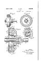
- I I Fig. 1 is a side elevation of a clutch embodving the invention
- Fig. 2 is a sectional elevation taken on line 22 of Fig. 1; p 7
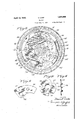
- Fig. 8 is an enlarged. sectional elevation taken on line 3-8 of Fig. 5;
- Fig. 41 is a fragmentary sectional elevation taken on line 1-4: of Fig. 5;
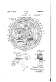
- Fig. 5 is a transverse section taken on line 5-5 of Fig. 3; r
- Fig. 7 is an end view of the shoe looking from the right of Fig. 6; I
- Fig. 8 is a view similar to Fig. 3, showing the shoes in operating position
- Fig. 9- is a detailed view of one of the actuating weights for the shoes.
- Fig. 10 is a detailed view of one of the iewed from the left of Fig. 10; V
- Fig. 13 is a detailed View of a driving disk shown applied at the left of Fig.3, and
- CLUTCH' Fig.14 is a sectio through the disktaken on line 1414 of Fig. 13.
- the clutch of the present invention hasbeen especially designed with smooth starting in view, and it has been found in actual use to give exceedingly favorable results. It is desirable in many instances to provide clutches with automatic engaging means, operable centrifugally or otherwise. When such automatic means is used,it is ordinarily constructed to engage the clutch after the driving member has attained a considerable speed. Under such conditions, when the clutch is exceptionally uniform andre'liable' in its engaging action, always engaging at the speed at which it is intended to engage, .without substantial variations commonly found in prior clutches.
- a driving shaft 11 which may be the armature shaft of a motor or may be driven in any other suitable way.
- a disk 12 is fixed to this driving shaft 11 by means of a pin 13 passing through an annular flange 14 on the disk 12 and into a hole in the shaft 11.
- the isk 12 rotates with the driving shaft'll.
- a plurality of clutching shoes 15 Movably mounted on the disk 12 is a plurality of clutching shoes 15. Three of such shoes are here shown, but the number may ob viously be varied as desired. Each of these shoes has a wide outer face substantially in the form of a segment of a cylinder, for engaging a band 16 placed Within an annular housing 17 which forms the driven member of the clutch, as will be described below. Each of these shoes also has a comp arative- 1y thick flange 18 extending radially inward- 1y from its peripheral segmental flange, as best shown in Fig. 6.
- the inner edge of the flange 18 of each shoe which is the edge contacting with the rollers 22, is not concentric with the outer pe ripheral surface of the shoe, but is slightly eccentric relative thereto so that the shoe may be said to be slightly taper-ed or wedge shaped.
- the numeral 23 indicates the center of curvature of the outer peripheral surface of the shoe, which is the surface contacting with the driven portion of the clutch, while the center of curvature of the inner surface of the flange 18 is shown at the point 24.
- the studs 20 near the thicker ends of the shoes are slightly closer to the center of the disk 12 than the studs 21 which are near the thinner end of the shoes.
- the outer periphery of each shoe will be substantially concentric with the axis of rotation of the disk 12. From the tapered construction of the shoes, it is obvious that if the shoes are moved circumferentially relative to the disk 12 in a counter-clockwise di rection when viewed as in Fig. 8, the shoes will at the same time move outwardly so that the outer peripheral surfaces thereof will be farther from the axis of rotation. On the other hand, if the shoes be moved circumferentially in a clockwise direction relative to the disk 12.
- each shoe is provided near What might be termed its thicker end with a stud 25, and an equalizing member such as the annular compensating ring 26 is provided with slots 27 in which these studs are received.
- the slots 27 have a width in a circumferential direction just sufficient to receive the studs 25, but in a radial direction these slots are elongated to allow the studs 25 to move in and out toward or away from the axis of rotation of the clutch during their circumferential move ment. It is apparent that this compensating ring 26 makes all of the shoes 15 move together, so that they are all equally expanded.
- the shaft 11 is driven in a clockwise direction when viewed as in Fig. 5.
- the friction between the driven member 17 and the shoes 15 011 the rotating driving member will tend to move these shoes in a countereclockwise direction. relative to the disk 12.
- Such direction of movement of the shoes is the direction which causes them to expand or move outwardly from the axis of rotation.
- Variousmeans may be employed for controlling the circumferential movements of the shoes 15 relative to the disk 12, in order to engage or disengage the clutch.
- the same rinci le of shoes movin circumferentiall Fig. 9 each of which has hole 31 which fits over one of the long studs 20, so that each of these long studs carries the weight pivotally mounted thereon.
- Each weight also has a notch 32 which embraces the stud 25 on the adjacent shoe 15, it being understood that the stud 25 is sufficiently long so that it pro jects upwardly through the slot 27 of the ring 26 and into the notch
- the main body of each weight 30 extends somewhat circumferentially for some distance from its clutch will have a strong tendency to move the weight outwardly,Whichwill cause it to turnin a counter-clockwise direction about its pivot 20, when viewed'as in Fig. 5. This counter-clockwise movement of the weight will act upon the studs 25 to move the shoes circumferentiallyin a counter-clockwise direction, so that the shoes willtravel upon the rollers 22 and be expanded to engage the .driven member," thus engaging the clutch ,45to flexible shafting.
- the construction of the friction band 16, which has previously been mentionedinpassing, is of considerable importance in the All of the shoes will have to move together and through the same distance, because of the equalizing member 26.
- a retaining plate 35 having the shape best shown in Fig. 10, overlies the weights 30 and retains them in position, the plate being held in place by being set on the endsof the long studs and having the ends. of thestuds riveted over the outer surface of the plate 35.
- Each weight is provided with a spring stud 36 projecting'upwardly to a point above the surface of the'plate 35, and this plate is provided with notches 37 so that these studs 36 may move freely in and out when the weights move to engage or disengage the clutch.
- the retaining plate 35 carries three spring studs 38 projecting from the outer face thereof, and to each of these studs there is fastened one end of a coiled spring 39, the
- a shaft is preferably fixed to the driven housing 17, this shaft being the driven shaft,
- a bearing bushing 46 is fixed in the driven housing 17, and surrounds the end of the driving shaftll, asshown in Fig. 3, toinsure accurate axial alinement' of the driving'parts with the driven parts.
- the driving shaft 11 may have a circumferential groove47 near its end, and a hole 48 is formed through thebearing bushing 46 i and the housing 17 in such position that when a pin 49 is inserted in this hole 48,. the pin will liepartially in the groove 47 thus holdingthe driven parts in position onthe shaft 11.
- retaining pin 49 maybe conveniently bent part way around the hub of the housing 17 as at 50 to form a spring clip, so that the pin is readily removable from its hole 48 when it is desiredto take the" clutch apart.
- the driven parts 16, 17, 45, and 46 maybe L entirely carried by the shaft 11 without other support, which-arrangement is especially convenient when it is desired to connect the shaft proper functioning of the clutch.
- It is preferably made of material suchas molded asbestos brake lining, although other materials. such as krome leather or pressed cork might be employed. When molded-. asbestos.
- lining or other relatively hard material is employed,it is preferable to notch or groove tervals aroundits circumference, these half way through the thickness of the band.
- Such grooves are shown at 55 in Fig. 8. These grooves make the relatively hard. material of the band sui'liciently flexible so that it can the exterior periphery thereof at shortingrooves preferably extending" approximately 9 conform closely to any irregularities in the I surface of the member 17. It is found by.
- the housing,l-7 miglitjbe 13 In a clutch, the combination with a driving member, of a driven member, a plurality of studs mounted on'said driving mem-. ber, a plurality of shoes guided by said studs for movement into and out of cooperative relation with said driven member, an equalizing member connected to each of said shoes to equalize the movement of the different.
- a clutch In a clutch, the combination with a driving member, of a driven member, a plurality of studs mounted on said driving member, a plurality of shoes guided by said studs for movement into and out of cooperative relation with said driven member, centrifugal controlling elements mounted on certain of said studs for controlling movement of said shoes, and a retaining member also mounted on saidfstuds for retaining said shoes in cooperative relation to said studs and said controlling elements in relation to said shoes.
- a clutch the combination with. a driving member, of a driven member, a plurality of studs mounted on said driving mem: ber, a plurality of shoes guided by said studs vfor movement'into and out of cooperative relation with said driven member, an equalizing member connected to each of said shoes to equalize the movement of the different shoes, centrifugal controlling elements mounted on certain of said studs for controlling movement of said shoes, and a retaining member also mounted on said studs for retaining said shoes in cooperative relation to said studs and retaining said equalizing member and controlling elements in cooperative relation to said shoes.
- a clutch the combination With a driving member including a disk-like portion, of a driven member, a plurality of studs mounted on said disk-like portion and projecting therefrom, rollers mounted on said studs, aplurality of shoes guided by said rollers for movement into and out of cooperation with said driven member, an equalizing ring 7 connected to said shoes to equalize the move- 'ment of the different shoes, controlling elements mounted on certain of said studs for controlling the movements'of said shoes, and
Description
D. LAKE CLUTCH April 12, 1932.
Filed Aug. 5, 1929 4 Sheets-Sheet 1 INVENTOR. 2620267 lake ATTORNEYS v D. LAKE CLUTCH A ril 12, 1932.
Filed Aug. 5, 1929 4 Sheets-Sheet 2 ya uz'czlaice BY Z 2 I zIsATmRNEY April 12, 1932. D. LAKE' CLUTCH Filed Aug. 5, 1929 4 Sheets-Sheet 5' TTORNEYS D. LAKE CLUTCH .April 12, 1932.
Filed Aug. 5, 1929 4 Sheets-Sheet 4 ORNEYS weight retaining plates;
' Fig. 11 shows the retaining plate as specification.
Patented Apr. 12, 1932 UNrrsn STATES PATENT caries DAVID LAKE, or CLEVELAND HEIGHTS, cLEvELANnonIo, assmnon'ro Anroivm'rm CLUTCH & nncnrnn 00., 1nd, or ennvnLAnn, owe, a conroaaprronor NEW YORK Application filed Auguste, 1929. Serial No. asaeevg This invention relates to a clutch, andhas for one of its objects the provision ofa clutch which will start its load smoothly and without erking even though it is engaged when the driving member of the clutch is'moving at high speed. I
Another object is the provision of an improved and satisfactory clutch which 'will en gage itself automatically When the driving member reaches a predetermined speed.
A further object is the provision of a gen-- erally improvedand more satisfactory clutch which is smoother in starting, more uniform and reliable in operation, and which will transmit more power in proportion to its size than other clutches heretofore known.
I To these and other ends the invention resides in certain improvements and combinations of parts, all as will be hereinafter more fully described, the novel features being pointed out in the claims at the end of this In the drawings: I I Fig. 1 is a side elevation of a clutch embodving the invention;
Fig. 2 is a sectional elevation taken on line 22 of Fig. 1; p 7
Fig. 8 is an enlarged. sectional elevation taken on line 3-8 of Fig. 5;
Fig. 41 is a fragmentary sectional elevation taken on line 1-4: of Fig. 5;
Fig. 5 is a transverse section taken on line 5-5 of Fig. 3; r
6 is a detailed view of one of the clutch shoes;
Fig. 7 is an end view of the shoe looking from the right of Fig. 6; I
Fig. 8 is a view similar to Fig. 3, showing the shoes in operating position;
Fig. 9- is a detailed view of one of the actuating weights for the shoes;
Fig. 10 is a detailed view of one of the iewed from the left of Fig. 10; V
12 is a sectional elevation taken'on line 1212 of Fig. 3; i
Fig. 13 is a detailed View of a driving disk shown applied at the left of Fig.3, and
CLUTCH' Fig.14 is a sectio through the disktaken on line 1414 of Fig. 13.
Similar reference numerals throughout the several views indicate the same parts.
When clutches are used in connection with certain types of machinery or appliances,
it is essential-j that the clutches be so constructed that they will engage smoothly and start the load gradually, withoutpjerking .or jarring. For instance, compressors of various types, washing machines, and wire drawing machines, to mention only a few,
should be started smoothly in order to ob' tain best results, :The clutch of the present invention hasbeen especially designed with smooth starting in view, and it has been found in actual use to give exceedingly favorable results. It is desirable in many instances to provide clutches with automatic engaging means, operable centrifugally or otherwise. When such automatic means is used,it is ordinarily constructed to engage the clutch after the driving member has attained a considerable speed. Under such conditions, when the clutch is exceptionally uniform andre'liable' in its engaging action, always engaging at the speed at which it is intended to engage, .without substantial variations commonly found in prior clutches.
Referring now to the drawings, there is shown a driving shaft 11 which may be the armature shaft of a motor or may be driven in any other suitable way. A disk 12 is fixed to this driving shaft 11 by means of a pin 13 passing through an annular flange 14 on the disk 12 and into a hole in the shaft 11. Thus the isk 12 rotates with the driving shaft'll.
Movably mounted on the disk 12 is a plurality of clutching shoes 15. Three of such shoes are here shown, but the number may ob viously be varied as desired. Each of these shoes has a wide outer face substantially in the form of a segment of a cylinder, for engaging a band 16 placed Within an annular housing 17 which forms the driven member of the clutch, as will be described below. Each of these shoes also has a comp arative- 1y thick flange 18 extending radially inward- 1y from its peripheral segmental flange, as best shown in Fig. 6.
Adj aoent each of the shoes 15, and slightly inwardly from the flange 18 of the shoe, are long studs 20 and short studs 21 fixed to'and projecting from the disk 12. On each of these studs is mounted a roller 22, and the shoes 15 are arranged so that the flanges 18 thereof contact with and may roll on these rollers 22.
The inner edge of the flange 18 of each shoe, which is the edge contacting with the rollers 22, is not concentric with the outer pe ripheral surface of the shoe, but is slightly eccentric relative thereto so that the shoe may be said to be slightly taper-ed or wedge shaped. In Fig. 6, the numeral 23 indicates the center of curvature of the outer peripheral surface of the shoe, which is the surface contacting with the driven portion of the clutch, while the center of curvature of the inner surface of the flange 18 is shown at the point 24.
The studs 20 near the thicker ends of the shoes are slightly closer to the center of the disk 12 than the studs 21 which are near the thinner end of the shoes. When the shoes have their flanges 18 in contact with the rollers 22, the outer periphery of each shoe will be substantially concentric with the axis of rotation of the disk 12. From the tapered construction of the shoes, it is obvious that if the shoes are moved circumferentially relative to the disk 12 in a counter-clockwise di rection when viewed as in Fig. 8, the shoes will at the same time move outwardly so that the outer peripheral surfaces thereof will be farther from the axis of rotation. On the other hand, if the shoes be moved circumferentially in a clockwise direction relative to the disk 12. they will be withdrawn or moved inwardly closer to the axis of rotation. This circumferential movement of the shoes thus expands or contracts them, and causes them to engage or disengage the friction band or ring 16 extending annularly around the in side of an annular housing 17 which forms the driven member of the clutch.
In a clutch of this type, it is important that all of the shoes should move into or out of engagement substantially simultaneously, thus preventing a greater load being thrown on one shoe than on another, which-would cause eccentric strains. In order to equalize the movements of all of the shoes, each shoe is provided near What might be termed its thicker end with a stud 25, and an equalizing member such as the annular compensating ring 26 is provided with slots 27 in which these studs are received. The slots 27 have a width in a circumferential direction just sufficient to receive the studs 25, but in a radial direction these slots are elongated to allow the studs 25 to move in and out toward or away from the axis of rotation of the clutch during their circumferential move ment. It is apparent that this compensating ring 26 makes all of the shoes 15 move together, so that they are all equally expanded.
Hence all of them engage the friction band 16 substantially simultaneously.
Preferably the shaft 11 is driven in a clockwise direction when viewed as in Fig. 5. Hence the friction between the driven member 17 and the shoes 15 011 the rotating driving member will tend to move these shoes in a countereclockwise direction. relative to the disk 12. Such direction of movement of the shoes is the direction which causes them to expand or move outwardly from the axis of rotation Thus it follows that when the clutch is once engaged, slippage of the clutch tends to engage the shoes still more firmly, so that the greater the load on the clutch, the greater is the pressure between the shoes and the driven member. This construction results in a clutch which is able to transmit a very large amount of power in proportion to its size.
Variousmeans may be employed for controlling the circumferential movements of the shoes 15 relative to the disk 12, in order to engage or disengage the clutch. In the present instance, it is preferred to provide automatic controlling means, working on the centrifugal principle, so that the clutch will be automatically engaged when the driving member reaches a predetermined speed, and will be automatically disengaged when the driving member falls below a predetermined speed. It is obvious, however, that the same rinci le of shoes movin circumferentiall Fig. 9, each of which has hole 31 which fits over one of the long studs 20, so that each of these long studs carries the weight pivotally mounted thereon. Each weight also has a notch 32 which embraces the stud 25 on the adjacent shoe 15, it being understood that the stud 25 is sufficiently long so that it pro jects upwardly through the slot 27 of the ring 26 and into the notch The main body of each weight 30 extends somewhat circumferentially for some distance from its clutch will have a strong tendency to move the weight outwardly,Whichwill cause it to turnin a counter-clockwise direction about its pivot 20, when viewed'as in Fig. 5. This counter-clockwise movement of the weight will act upon the studs 25 to move the shoes circumferentiallyin a counter-clockwise direction, so that the shoes willtravel upon the rollers 22 and be expanded to engage the .driven member," thus engaging the clutch ,45to flexible shafting. I p The construction of the friction band 16, which has previously been mentionedinpassing, is of considerable importance in the All of the shoes will have to move together and through the same distance, because of the equalizing member 26.
- A retaining plate 35, having the shape best shown in Fig. 10, overlies the weights 30 and retains them in position, the plate being held in place by being set on the endsof the long studs and having the ends. of thestuds riveted over the outer surface of the plate 35. Each weight is provided with a spring stud 36 projecting'upwardly to a point above the surface of the'plate 35, and this plate is provided with notches 37 so that these studs 36 may move freely in and out when the weights move to engage or disengage the clutch. The retaining plate 35 carries three spring studs 38 projecting from the outer face thereof, and to each of these studs there is fastened one end of a coiled spring 39, the
other end of the spring being fastened to the stud 36 on one of t e weights 30. It is apparent that as the weights move outwardly to clutch engaging position, the springs 39 will be stretched, and the speedat Which the clutch automatically engages accordingly depends principally upon the mass and shape of the weights 30 and the strength of-the springs 39. The weights 30 and the springs '39 may thus be varied asdesired in order that the clutch mayhave any desired speed. Of course, in addition to the centrifugal action of the Weights 30, centrifugal force acts also directly on the shoe-s 15, so that regardless ,of the weights there is some tendency-for the shoes to move outwardly and engage the driven member. 7
A shaft is preferably fixed to the driven housing 17, this shaft being the driven shaft,
and it is suitably connected to themachine or appliance to which power is being sup plied.- Preferably a bearing bushing 46 is fixed in the driven housing 17, and surrounds the end of the driving shaftll, asshown in Fig. 3, toinsure accurate axial alinement' of the driving'parts with the driven parts. To prevent longitudinal displacement of the driven member relative to the driving memher, the driving shaft 11 may have a circumferential groove47 near its end, and a hole 48 is formed through thebearing bushing 46 i and the housing 17 in such position that when a pin 49 is inserted in this hole 48,. the pin will liepartially in the groove 47 thus holdingthe driven parts in position onthe shaft 11. uThe end of the retaining pin 49 maybe conveniently bent part way around the hub of the housing 17 as at 50 to form a spring clip, so that the pin is readily removable from its hole 48 when it is desiredto take the" clutch apart. When retaining lmeans such as this pin 49: and groove 47 is employed,
the driven parts 16, 17, 45, and 46 maybe L entirely carried by the shaft 11 without other support, which-arrangement is especially convenient when it is desired to connect the shaft proper functioning of the clutch. It is preferably made of material suchas molded asbestos brake lining, although other materials. such as krome leather or pressed cork might be employed. When molded-. asbestos.
lining or other relatively hard material is employed,it is preferable to notch or groove tervals aroundits circumference, these half way through the thickness of the band. Such grooves are shown at 55 in Fig. 8. These grooves make the relatively hard. material of the band sui'liciently flexible so that it can the exterior periphery thereof at shortingrooves preferably extending" approximately 9 conform closely to any irregularities in the I surface of the member 17. It is found by.
freeto move circumferentially around the housing. Of course, when the clutch is fully engaged, there will be littleor'no movement between the band 16 and the housing 17 because the shoes 15 will press the band 16 against the housing so tightly that friction preventssuch movement. But. when the clutch is being engaged, thebandfisfree to slip somewhatin the housing, andat the over. the band, which results inan extremely smooth and vibrationless starting, even at same time the shoes 15 may slip somewhat quite high speeds. Clutches have been made according to this invention which are so proportioned that they engage automatically at a speed of approximately 1500 revolutions per minute. and such clutchesduring repeated tests under varying conditions have functioned perfectly, starting the load with remarkable smoothness.
In these clutches, when the speed of'the driving shaft falls to a point slightly below Y the speed at which the clutch automatically engages, the springs 39 will automatically disengage the clutch.
v I It is obvious that the housing,l-7 miglitjbe 13. In a clutch, the combination with a driving member, of a driven member, a plurality of studs mounted on'said driving mem-. ber, a plurality of shoes guided by said studs for movement into and out of cooperative relation with said driven member, an equalizing member connected to each of said shoes to equalize the movement of the different.
shoes, and a plate mounted on said studs to retain said shoes in cooperative relation to" sald studs and sald equalizing member in 00- operative relation to said shoes. 7
14:. In a clutch, the combination with a driving member, of a driven member, a plurality of studs mounted on said driving member, a plurality of shoes guided by said studs for movement into and out of cooperative relation with said driven member, centrifugal controlling elements mounted on certain of said studs for controlling movement of said shoes, and a retaining member also mounted on saidfstuds for retaining said shoes in cooperative relation to said studs and said controlling elements in relation to said shoes.
15. In a clutch, the combination with. a driving member, of a driven member, a plurality of studs mounted on said driving mem: ber, a plurality of shoes guided by said studs vfor movement'into and out of cooperative relation with said driven member, an equalizing member connected to each of said shoes to equalize the movement of the different shoes, centrifugal controlling elements mounted on certain of said studs for controlling movement of said shoes, and a retaining member also mounted on said studs for retaining said shoes in cooperative relation to said studs and retaining said equalizing member and controlling elements in cooperative relation to said shoes.
16. In a clutch, the combination with a driving member, of a driven member, a stud mounted on said driving member, a shoe guided by saidstud for movement into and out of cooperative relation with said driven member, a centrifugal controlling element cooperative relation to said shoe, and a coiled spring connected at one end to said retaining member and at the other end to said'controlling element. f
1 7. In a clutch, the combination With a driving member including a disk-like portion, of a driven member, a plurality of studs mounted on said disk-like portion and projecting therefrom, rollers mounted on said studs, aplurality of shoes guided by said rollers for movement into and out of cooperation with said driven member, an equalizing ring 7 connected to said shoes to equalize the move- 'ment of the different shoes, controlling elements mounted on certain of said studs for controlling the movements'of said shoes, and
retaining means mounted on said studs for.
retaining said rollers,'shoes, equalizing ring, and controlling elements 1n cooperatlve relation to each other.
DAVID LAKE.
for controlling movement of said shoe, a I
Priority Applications (1)
| Application Number | Priority Date | Filing Date | Title |
|---|---|---|---|
| US383607A US1853908A (en) | 1929-08-05 | 1929-08-05 | Clutch |
Applications Claiming Priority (1)
| Application Number | Priority Date | Filing Date | Title |
|---|---|---|---|
| US383607A US1853908A (en) | 1929-08-05 | 1929-08-05 | Clutch |
Publications (1)
| Publication Number | Publication Date |
|---|---|
| US1853908A true US1853908A (en) | 1932-04-12 |
Family
ID=23513897
Family Applications (1)
| Application Number | Title | Priority Date | Filing Date |
|---|---|---|---|
| US383607A Expired - Lifetime US1853908A (en) | 1929-08-05 | 1929-08-05 | Clutch |
Country Status (1)
| Country | Link |
|---|---|
| US (1) | US1853908A (en) |
Cited By (6)
| Publication number | Priority date | Publication date | Assignee | Title |
|---|---|---|---|---|
| US2534426A (en) * | 1947-03-05 | 1950-12-19 | Ind Clutch Corp | Centrifugal clutch |
| US2762484A (en) * | 1952-06-02 | 1956-09-11 | Terence G Hare | Centrifugal friction type clutch with chain member |
| US3208571A (en) * | 1960-01-04 | 1965-09-28 | Bochory Michael | Centrifugally operated clutch mechanism |
| DE1284714B (en) * | 1966-07-16 | 1968-12-05 | Kaleja Heinrich | Coupling for smooth starting of a driven shaft |
| US3603178A (en) * | 1968-11-15 | 1971-09-07 | Fichtel & Sachs Ag | Multiple-speed bicycle hub with centrifugal governor |
| US4345664A (en) * | 1979-05-23 | 1982-08-24 | Honda Giken Kogyo Kabushiki Kaisha | Power transmission for two-wheeled vehicle |
-
1929
- 1929-08-05 US US383607A patent/US1853908A/en not_active Expired - Lifetime
Cited By (7)
| Publication number | Priority date | Publication date | Assignee | Title |
|---|---|---|---|---|
| US2534426A (en) * | 1947-03-05 | 1950-12-19 | Ind Clutch Corp | Centrifugal clutch |
| US2762484A (en) * | 1952-06-02 | 1956-09-11 | Terence G Hare | Centrifugal friction type clutch with chain member |
| US3208571A (en) * | 1960-01-04 | 1965-09-28 | Bochory Michael | Centrifugally operated clutch mechanism |
| DE1284714B (en) * | 1966-07-16 | 1968-12-05 | Kaleja Heinrich | Coupling for smooth starting of a driven shaft |
| US3603178A (en) * | 1968-11-15 | 1971-09-07 | Fichtel & Sachs Ag | Multiple-speed bicycle hub with centrifugal governor |
| US4345664A (en) * | 1979-05-23 | 1982-08-24 | Honda Giken Kogyo Kabushiki Kaisha | Power transmission for two-wheeled vehicle |
| US4475893A (en) * | 1979-05-23 | 1984-10-09 | Honda Giken Kogyo Kabushiki Kaisha | Power transmission for two-wheeled vehicle |
Similar Documents
| Publication | Publication Date | Title |
|---|---|---|
| US2100464A (en) | Friction clutch | |
| US2496201A (en) | Speed responsive clutch mechanism | |
| US1853908A (en) | Clutch | |
| US1851146A (en) | Automatic clutch | |
| US2087488A (en) | Friction clutch | |
| US2016643A (en) | Centrifugal clutch | |
| US2718294A (en) | Automatic, centrifugal clutch mechanisms | |
| US3680674A (en) | Centrifugal clutch | |
| US2851893A (en) | Speed responsive clutch | |
| US2138129A (en) | Clutch | |
| US3164236A (en) | Clutch plates and the like | |
| US2144443A (en) | Lagging clutch pulley structure | |
| US3183730A (en) | High speed spindle assembly | |
| US3367464A (en) | Centrifugal clutch | |
| US2852117A (en) | Centrifugal clutch construction | |
| US2217529A (en) | Friction clutch | |
| US2422533A (en) | Clutch | |
| US2002699A (en) | Clutch | |
| US2027970A (en) | Centrifugal clutch | |
| US2909073A (en) | Speed responsive clutch | |
| US1268632A (en) | Flexible coupling. | |
| US2445590A (en) | Driving mechanism | |
| US2278556A (en) | Friction clutch | |
| US2307175A (en) | Yieldable means | |
| US1718105A (en) | Friction clutch |