US1853906A - Brake - Google Patents
Brake Download PDFInfo
- Publication number
- US1853906A US1853906A US334734A US33473429A US1853906A US 1853906 A US1853906 A US 1853906A US 334734 A US334734 A US 334734A US 33473429 A US33473429 A US 33473429A US 1853906 A US1853906 A US 1853906A
- Authority
- US
- United States
- Prior art keywords
- brake
- drum
- plate
- bracket
- arm
- Prior art date
- Legal status (The legal status is an assumption and is not a legal conclusion. Google has not performed a legal analysis and makes no representation as to the accuracy of the status listed.)
- Expired - Lifetime
Links
Images
Classifications
-
- F—MECHANICAL ENGINEERING; LIGHTING; HEATING; WEAPONS; BLASTING
- F16—ENGINEERING ELEMENTS AND UNITS; GENERAL MEASURES FOR PRODUCING AND MAINTAINING EFFECTIVE FUNCTIONING OF MACHINES OR INSTALLATIONS; THERMAL INSULATION IN GENERAL
- F16D—COUPLINGS FOR TRANSMITTING ROTATION; CLUTCHES; BRAKES
- F16D51/00—Brakes with outwardly-movable braking members co-operating with the inner surface of a drum or the like
- F16D51/02—Brakes with outwardly-movable braking members co-operating with the inner surface of a drum or the like shaped as one or more circumferential band
- F16D51/04—Brakes with outwardly-movable braking members co-operating with the inner surface of a drum or the like shaped as one or more circumferential band mechanically actuated
Definitions
- This invention relates to vehicle brakes andparticularly to means adapted to compensate for the wear of the brake lining.
- it has been the common prac- 6 tice to periodically adjust the brake element relative to the brake drum because of the wear of the A brake lining and for other reasons.
- yTo adjust the braking element it has been necessary to'manually change the position of cams', rollers or other stop mecha nisms against which the brake-element seats when in inoperative position.
- the so-called 'adjustment of the brakes requires considerable time and it has been found that the operator of the vehicle .often waits until the brakes are in faulty condition before making the necessary adjustments.
- A. further object is to provide a plate hav,- ing a serrated surface attached to the back ing plate, and a member having a corre- Mlsponding serrated surface vmovable relative lto the plate, the member beingy moved relative to said plate by movement of thebrak- 'I ing element to automatically compensate for the ⁇ wear of the brake properly operate and in many cases which of Figure 5.
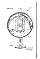
- Flgure 1 is a side elevation of a vehicle brake including my invention, showing the brake drum and the wheel spindle in section.
- Figure 2 is an enlarged side elevation of the device for compensating for .the wear of the brake lining, the brake element and the brake lining being shown in section.
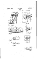
- Figure 3 1s a section taken on the line3-3 of Figure 1,' certain parts being broken away the invention.V
- Figure 5 is a side elevation corresponding ⁇ with Figure 2,"sl1'owing'a modified formof. my lnvention.
- Figure 6 is a section taken on the line 6--6
- Figure 7 is a' of the operating arm shown in Figure 5.
- Figure Si an edge view of the 'arm shown in Figure 7.
- Figure 9 is a face view of the plate adapted to be attached tothe bacldng plate shown in Figure 5; f n
- Thebrake mechanism which I have shown for the purpose of illustration comprises a .and others 1n elevation to more clearly show 'i fragmentary side elevation l of the brake shoe 15, the plate 18 and stop 17 to prevent transverse movement of the brake shoe 15, the plate 18 and stop 17 being secured to the backing plate 13 by means of thescrews 19.
- the brake element chosen for illustration . is of the full Heating internal expansion type, that is, the type wherein the brake element ⁇ rotates substantial amount with the brake drum to apply greaterbraking effort.
- a pair of links 20 are pivoted by means of the pins 21 to the webs or reinforcements 16 of the brake shoe 15.
- the free ends of the links 20 are interconnected by a U-shaped operating bar 22 pivoted thereto by means of the pivot pins 23.
- Enlarged openings 24 are formed in the web 16 of the brake shoe 15 for the pins 23 to extend therethrough and move therein.
- the bar 22 is actuated by means of a bell crank pivoted to the backing plate ,13 by a pin 25 and has onearm 26 pivotally attached to the operating bar 22 intermediate its ends by a pin 27.
- the other bell crank arm 28 terminates in a linger 29 disposed at right angles, thereto and extending through 5 a slot 30cut in the backing plate 13..
- finger 29 just mentioned is positioned dlrectly above the steering knuckle king pin and 1s formed with a flat lower surface.
- the means for actuating the brakes may be of the t e shown in the application for patent by drew P. Wisner, Serial No. 334,707,
- v pair of springs 32 connected at their adjacent ends to the stop member 17 and at their op- -to the arm 41 without distributing its posiposite ends to Abrackets 32 secured to the brake element 11j are employed to normally retainy the bra e element 15 in disengage- 'ment with the brake drum 12.
- the present invention relates to means which automatically compensates for the wear of the brake lining 15 so that a predetermined clearance between the brake drum 12 and the brake lining 15 is at all times insured when the brake element ⁇ 15 v'together with the brake lining 15 is in inoperative position.
- a plate 33 secured to the backing plate 13 which has teeth 34 formed in the exposed face thereof.
- a support which may be a, post 35 is adapted to extend through an opening 36 formed in the plate 33 and through the backing late 13 to be supported thereby and retainedp thereon by the nut 37.
- a bracket 38 having a slot 39 therein is secured to the brake element 15 in line'with the support'35 and is connected thereto by means of the spring 40. It will thus be seen that the Vbrake element is normally held out of engagement with the brake drum 15 by means of the spring 40 connected between the bracket 38 and the post 35, and that when the brake element 15 is moved into initial engagement with the b rake drum 12, tension is exerted on the spring 40.
- An arm 41 is mounted on the support 35 and has teeth 42 formed in the face thereof which engage with the teeth 34 formed in the face of the plate 33.
- the arm 41 is provided with a slot 43 which will permit radial movement thereof relative to the backing plate 13 for a purpose to be hereinafter described.
- the arm 41 is resiliently held in engagement with the plate 33 by means of the spring 44 surrounding the support 435 which engages the arm 41 at one end and a stop 45 at its other end positioned on the support 35.
- the arm 41 has a post 46 extending therefrom on which is mounted a roller 47, the same being retained a ainst longitudinal movement by means of t e pin 48 and the collar 49.
- the roller 47 is adapted to ride in the slot 39 formed in the bracket 38.
- the width of the slot 39 is greater than the diameter of the roller 47 which permits the bracket 38 and, therefore, the brake element 15 to have limited movement relative tion on the support 35..
- the clearance between the brake element and the 'brake drum is determined and at that time theI arm 41 is adjusted o n the post 35 so that the roller 47 seats -on the edge of the slot 39 ⁇ as shown in Figure 3 when the brake element is in inoperative position.
- the clearance between the roller47 andthe opposite edge -of the slot 39 is s ub- 130 stantially the same as the clearance between the brakelining 15 and the drum 12.
- Ay brake comprising, in combination, a drum, a iiexible brake element including a friction memberengageable with said drum, a stop member positioned between and adapted to be engaged by the free ends ofsaid brake element, means for bodily moving saidfriction member radially of said drum into partial engagement therewith and 'then expanding said member -into complete engagement therewith, and spring tensioned means positioned opposite the free ends of said brake element operable by the bodily movement of said brake element to resiliently maintain saidbrake element in a position to automatically compensate for the wear ,of said friction member.
- a brake comprising, in combination, a drum, a backing member adjacent thereto, a brake element including a friction member engageable with said drum, means for moving said friction member into engagement with said drum, means to compensate for the wear of said friction member comprising, a plate secured to said backing member, a bracket secured to said brake element, and a member. movable by said bracket frictionally ment with said drum.
- said friction member comprising, a plate having a serrated surface secured to said backin member, a slotted bracket securedto said rake element, and a member having a serrated surface engageable with the serrated surface of said plate and having a projecting portion extending .into the slot ofsaid brac et whereby said member is moved relative to 4said plate by movement of said brake element.
- a brake comprising, incombination, a drum, a'backing member adjacent thereto, afl15 brake element includingV a friction member engageable with said drum, means for mov.
- a plate having a serrated-surface secured to said backing member, a bracket secured to said brake element, a member engageable with said bracket having a serrated 'surface adapted toengage the serrated surface of said plate, means to support said-member on said backing 'member, and ⁇ means to permitl movement of said member relative to said plate.
- a brake element including a friction member engageable with said drum, means for mov* ing said friction member into engagement with said drum, and means to compensate for the wear of said friction member comprising, a plate having a serrated surface secured to said backing member, a support extending 4 through said plate mounted on said backing member, a bracketsecured to said brake element, a member engageable with said bracket and having movement relative thereto carried by said support, said member having a serrated surface engageable with ,the serrated surface of said plate, and means to permit movement of said member relative to said plate.
- a brake comprising, a drum, a backing member adjacent thereto, a brake element including a friction member engageable with said drum, and means for moving said -friction member into engagement with said drum, having in combination therewith, a support mounted on said backing member, a
- said brake drum comprising, a bracket on said brake shoe, a post on said backing plate, a tension spring extending between said post and said bracket, and means for automatically limiting the action of said spring, said last named means comprising, a slot in said bracket, a serrated portion on the surface of said backing plate surrounding said post, an arm having an extenslon in said slot and a serrated surface for engagement with the serrations on said backing plate, and
- an arm having on one i end an extension for engagement with said brake shoe, and on the other end a serrated surface for operative engagement with the serrations on saidl backing plate.
- a brake shoe a brake drum, a backing plate, means. for moving said brake shoe awayfrom said brake drum comprising, a bracket Xed-on said brake shoe, a post xed on said backing late, resilient means between said bracket an said post, and stop means for said resilient means, said stop, means com risin a serrated portion on the surface o said acking plate, an arm having on one end an extension for enga ement with said bracket, and in the other en a slot adapted to surround said post and a serrated surface for operative engagement with the serrations on said backing plate.
- A; self adjusting brake comprising, a
Description
April 12, 1932. lR. F. om 1,853,906
BRAKE Filed Jan. 24, 1929 2 Sheets-Sheet l ATTORY April 12, .1932. R. F. KOHR #1,853,906
BRAKE Filed Jan. 24, 1929 2 Sheets-Sheet 2 INVENTOR.
Patented 'Api'. 12, 19.32
Ium'ri-:u`s'1"1 ..rl.l?.s' PATENT oFFlcs ROBERT F. KOHB, 0F SOUTH BEND, INDIANA, ASSIGNOR T0 THE STUDEBAKEB PORATON, OF SOUTH BEND, A COBPOBATIONOF NEW JERSEY Application mea January 24, 192|). serial no. 334,134.
The above being among the objects of the This invention relates to vehicle brakes andparticularly to means adapted to compensate for the wear of the brake lining. In the past it has been the common prac- 6 tice to periodically adjust the brake element relative to the brake drum because of the wear of the A brake lining and for other reasons. yTo adjust the braking element it has been necessary to'manually change the position of cams', rollers or other stop mecha nisms against which the brake-element seats when in inoperative position. The so-called 'adjustment of the brakes requires considerable time and it has been found that the operator of the vehicle .often waits until the brakes are in faulty condition before making the necessary adjustments. As the space between the brake lining andthe brake drum varies considerably fromtime to -time due to the wear of the brake lining, it has heretofore been the common practice of practical'- ly all owners of vehicles to operate the car until the brakes are badly out of adjustment thus often resulting in lbrakes which do not do not comply with the laws of many of the States. l
Having in mind the diliculties which have heretofore been encountered in keeping the brakes in adjustment, it is the principal object of my invention to providemeans operated by the movement of the braking element 4to automatically wear of the brake lining'` A further object is to provide means which4 will automatically maintain a jpredetermined clearance between the brake lining and the brake drum when thelbraking ele-v ment is-in inoperative position, the adjusting means being o erated by the initial engagement of the rake lining with the' brake drum. -1
A. further object is to provide a plate hav,- ing a serrated surface attached to the back ing plate, and a member having a corre- Mlsponding serrated surface vmovable relative lto the plate, the member beingy moved relative to said plate by movement of thebrak- 'I ing element to automatically compensate for the `wear of the brake properly operate and in many cases which of Figure 5.
compensate for the present invention, the same consists of certam `features and combination of parts to be hereinafter described, and then claimed hav- 1n the above and other objects in view.
" ferrinot) the drawings which show a.
suitable em iment of my invention,
Figure 3 1s a section taken on the line3-3 of Figure 1,' certain parts being broken away the invention.V
Figure 5 is a side elevation corresponding `with Figure 2,"sl1'owing'a modified formof. my lnvention.
Figure 6 is a section taken on the line 6--6 Figure 7 is a' of the operating arm shown in Figure 5.
Figure Sis an edge view of the 'arm shown in Figure 7. Figure 9 is a face view of the plate adapted to be attached tothe bacldng plate shown in Figure 5; f n
Referring to the numbered parts 'of' the drawings in which like numerals refer to like parts throughout the several views, I have shown a stub axle 10 secured toaffsteering knuckle 11 mounted on a vehicle'faxle (not A brake drum v12 mounted lin any desired manner on a vehicle wheel is adapted' to rotate relative to the axle 10. A dust coveror backing plate 13 yis mounted on thesteering brake mechanism.
Thebrake mechanism which I have shown for the purpose of illustration comprises a .and others 1n elevation to more clearly show 'i fragmentary side elevation l of the brake shoe 15, the plate 18 and stop 17 to prevent transverse movement of the brake shoe 15, the plate 18 and stop 17 being secured to the backing plate 13 by means of thescrews 19.
The brake element chosen for illustration .is of the full Heating internal expansion type, that is, the type wherein the brake element `rotates substantial amount with the brake drum to apply greaterbraking effort. The
operating means for theA brake element is like 20 that shown in my co-pending application ,Serial No. 334,733 filed on even date here with and therefore a detailed description of the same is believed to be unnecessary, I will,
. therefore, refer to the same only briefly to ,-describe the operation of the brake element Vand its relation to the means adapted to compensate for the wear of the brake lining which is the subject matter of the present invention. Y
A pair of links 20 are pivoted by means of the pins 21 to the webs or reinforcements 16 of the brake shoe 15. The free ends of the links 20 are interconnected by a U-shaped operating bar 22 pivoted thereto by means of the pivot pins 23. Enlarged openings 24 are formed in the web 16 of the brake shoe 15 for the pins 23 to extend therethrough and move therein. The bar 22 is actuated by means of a bell crank pivoted to the backing plate ,13 by a pin 25 and has onearm 26 pivotally attached to the operating bar 22 intermediate its ends by a pin 27. The other bell crank arm 28 terminates in a linger 29 disposed at right angles, thereto and extending through 5 a slot 30cut in the backing plate 13.. The
[finger 29 just mentioned is positioned dlrectly above the steering knuckle king pin and 1s formed with a flat lower surface.
,v The means for actuating the brakes may be of the t e shown in the application for patent by drew P. Wisner, Serial No. 334,707,
filed on even date herewith, although any other suitable lmeans may be employed for actuating the brake element as the same forms no part of this invention. I have shown a ball member 31 which can be moved vertically in any desiredmanner for rocking the bell crank lever on its pivot25 which in turn will cause the bar 22 to operate the links 6r 20 to first move the brake element 15 bodily relative to the brake drum into initial contact therewith and then' expand the same into c'olnplete engagement with the brake drum. A
v pair of springs 32 connected at their adjacent ends to the stop member 17 and at their op- -to the arm 41 without distributing its posiposite ends to Abrackets 32 secured to the brake element 11j are employed to normally retainy the bra e element 15 in disengage- 'ment with the brake drum 12.
The present invention relates to means which automatically compensates for the wear of the brake lining 15 so that a predetermined clearance between the brake drum 12 and the brake lining 15 is at all times insured when the brake element` 15 v'together with the brake lining 15 is in inoperative position.
Referring to Figures 1 to 4 inclusive, I have'provided a plate 33 secured to the backing plate 13 which has teeth 34 formed in the exposed face thereof. A support which may be a, post 35 is adapted to extend through an opening 36 formed in the plate 33 and through the backing late 13 to be supported thereby and retainedp thereon by the nut 37. A bracket 38 having a slot 39 therein is secured to the brake element 15 in line'with the support'35 and is connected thereto by means of the spring 40. It will thus be seen that the Vbrake element is normally held out of engagement with the brake drum 15 by means of the spring 40 connected between the bracket 38 and the post 35, and that when the brake element 15 is moved into initial engagement with the b rake drum 12, tension is exerted on the spring 40. An arm 41 is mounted on the support 35 and has teeth 42 formed in the face thereof which engage with the teeth 34 formed in the face of the plate 33. The arm 41 is provided with a slot 43 which will permit radial movement thereof relative to the backing plate 13 for a purpose to be hereinafter described. y
The arm 41 is resiliently held in engagement with the plate 33 by means of the spring 44 surrounding the support 435 which engages the arm 41 at one end and a stop 45 at its other end positioned on the support 35. The arm 41 has a post 46 extending therefrom on which is mounted a roller 47, the same being retained a ainst longitudinal movement by means of t e pin 48 and the collar 49. The roller 47 is adapted to ride in the slot 39 formed in the bracket 38. e
Referring to Figures 1, 2 and 3, it will be seen that the width of the slot 39 is greater than the diameter of the roller 47 which permits the bracket 38 and, therefore, the brake element 15 to have limited movement relative tion on the support 35..
, In the assemblyI of the brake and the brake operating mechanism, the clearance between the brake element and the 'brake drum is determined and at that time theI arm 41 is adjusted o n the post 35 so that the roller 47 seats -on the edge of the slot 39`as shown in Figure 3 when the brake element is in inoperative position. The clearance between the roller47 andthe opposite edge -of the slot 39 is s ub- 130 stantially the same as the clearance between the brakelining 15 and the drum 12. Thus it will be seen that as the brake element .15 is moved' bodily of the drum 12 the brake lm# ing 15 will have initial engagement with the come worn a slight amount the normal clearl,
ance vbetween the same and the brake drum 12 will be increased and therefore a greater initial movement of the brake element 15 is reuiredto apply the brake lining 15 to the rum. In the latter case, the upper edge of the slotl 39 will contact' with the roller 47 which will move the arm 41 on the support and will thus cause the teeth 42 thereon to ride on the teeth 34 formed in the face of the bracket 33. y
When the brake lining has become worn an amount equal to the distance between the apex of the teeth formed on the arm 41 and the bracket 33, the initial movement of the brake element willjcause the arm 41 to be moved so that the teeth 42 will engage with the next succeeding tooth 34 in the plate 33. Thus it will be seen that as the brake lining 15 becomes worn the initial movement of the brake element will cause the teeth 42 to ride on the teeth 34 against the tension of .the spring 44 to engage the next successive tooth and that such movement will automatically compensate for the wear of the brake lin ing 15.
l In Fi res 5 to 9 inclusive, I have shown a modifie form of my invention which comon the support 53 has teeth- 54 formed radialy prises a bracket secured to the backing plate 13, the plate 51 havingserrations orteeth formed'radiallythereof. Anarm52supported ly thereon adapted to engage withthe teeth 51 formed on theplate 50.V The arm 52 is resilicntly held against the plate 50 by means of the spring 55 mounted on` the support A53 "and engagedV between the arm 52 and thestop 56 on the support 53,A A post 57 is mounted on the free endof the arm 52 and has a roller 58 supported thereby which is .adapted to ride in the slot 3f) formed in the bracket 38 in exactly the same manner as. the roller-47 carried by the bracket 41V as shown inFigure 3. As the brake-lining'l is moved into inengagement with the next successive tooth to compensate forthe wearof. the brake1in-j ing 15.
Havmg described my invention it -will be apparent that formal changes may bevmade in the Specific embodimentl of the invention described without departing from the spirit and substance of the broad invention, the scope of which is commensurate with the appended claims.
What I claiml is:
1. Ay brake comprising, in combination, a drum, a iiexible brake element including a friction memberengageable with said drum, a stop member positioned between and adapted to be engaged by the free ends ofsaid brake element, means for bodily moving saidfriction member radially of said drum into partial engagement therewith and 'then expanding said member -into complete engagement therewith, and spring tensioned means positioned opposite the free ends of said brake element operable by the bodily movement of said brake element to resiliently maintain saidbrake element in a position to automatically compensate for the wear ,of said friction member.
2. A brake comprising, in combination, a drum, a backing member adjacent thereto, a brake element including a friction member engageable with said drum, means for moving said friction member into engagement with said drum, means to compensate for the wear of said friction member comprising, a plate secured to said backing member, a bracket secured to said brake element, and a member. movable by said bracket frictionally ment with said drum. and means to compensate for the wear of said friction member comprising, a plate having a serrated surface secured to said backin member, a slotted bracket securedto said rake element, and a member having a serrated surface engageable with the serrated surface of said plate and having a projecting portion extending .into the slot ofsaid brac et whereby said member is moved relative to 4said plate by movement of said brake element.
V,4. A brake comprising, incombination, a drum, a'backing member adjacent thereto, afl15 brake element includingV a friction member engageable with said drum, means for mov.-
ing said' friction member into engagement with said drum, and means to compensate for the wear of said friction member comprising,
a plate having a serrated-surface secured to said backing member, a bracket secured to said brake element, a member engageable with said bracket having a serrated 'surface adapted toengage the serrated surface of said plate, means to support said-member on said backing 'member, and` means to permitl movement of said member relative to said plate.
* 5. v A-brake comprising, incombination,` a
was .0r
drum, a baeking member adjacent thereto, a brake element including a friction member engageable with said drum, means for mov* ing said friction member into engagement with said drum, and means to compensate for the wear of said friction member comprising, a plate having a serrated surface secured to said backing member, a support extending 4 through said plate mounted on said backing member, a bracketsecured to said brake element, a member engageable with said bracket and having movement relative thereto carried by said support, said member having a serrated surface engageable with ,the serrated surface of said plate, and means to permit movement of said member relative to said plate.
6. A brake comprising, a drum, a backing member adjacent thereto, a brake element including a friction member engageable with said drum, and means for moving said -friction member into engagement with said drum, having in combination therewith, a support mounted on said backing member, a
.plate mounted on said backing member through which said support extends, a member carried by said support, a spring member mounted on said support for maintaining said member in contact with said plate, and a bracket secured to said' braking element having a slot therein adapted to receive said member whereby movement of said braking member causes said member to move relative to said plate against the tension of said spring means to compensate for the wear of said friction member.
7. In a self adjusting brake, a-brake shoe,
`a brake drum, a backin plate, means including a resilient member or moving said brake shoe/ away from said-drum, and stop means for said resilient member, said stop means comprising a serra-ted portion on the surface complete engagement with said brake drum, a backing plate, means for contracting said b rake shoe, and means for moving the init1ally engaging portion of said brake shoe away from said brake drum, said last named means comprising, a bracket flxed on said brake shoe, a post fixed on said backing plate,
from said brake drum comprising, a bracket on said brake shoe, a post on said backing plate, a tension spring extending between said post and said bracket, and means for automatically limiting the action of said spring, said last named means comprising, a slot in said bracket, a serrated portion on the surface of said backing plate surrounding said post, an arm having an extenslon in said slot and a serrated surface for engagement with the serrations on said backing plate, and
resilient means for retaining the said serrated faces in operative engagement.
Signed by me at South Bend, Indiana, this 21st day of January, 1929.
- f 'WROBERT F. KOHR.
of said backing plate, an arm having on one i end an extension for engagement with said brake shoe, and on the other end a serrated surface for operative engagement with the serrations on saidl backing plate.
8. In a self adjusting brake, a brake shoe, a brake drum, a backing plate, means. for moving said brake shoe awayfrom said brake drum comprising, a bracket Xed-on said brake shoe, a post xed on said backing late, resilient means between said bracket an said post, and stop means for said resilient means, said stop, means com risin a serrated portion on the surface o said acking plate, an arm having on one end an extension for enga ement with said bracket, and in the other en a slot adapted to surround said post and a serrated surface for operative engagement with the serrations on said backing plate. 9. A; self adjusting brake comprising, a
l brake drum, a brake shoe bodily movable for initial engagement of one portion thereof i 65 said brake drum and expandible for
Priority Applications (1)
| Application Number | Priority Date | Filing Date | Title |
|---|---|---|---|
| US334734A US1853906A (en) | 1929-01-24 | 1929-01-24 | Brake |
Applications Claiming Priority (1)
| Application Number | Priority Date | Filing Date | Title |
|---|---|---|---|
| US334734A US1853906A (en) | 1929-01-24 | 1929-01-24 | Brake |
Publications (1)
| Publication Number | Publication Date |
|---|---|
| US1853906A true US1853906A (en) | 1932-04-12 |
Family
ID=23308576
Family Applications (1)
| Application Number | Title | Priority Date | Filing Date |
|---|---|---|---|
| US334734A Expired - Lifetime US1853906A (en) | 1929-01-24 | 1929-01-24 | Brake |
Country Status (1)
| Country | Link |
|---|---|
| US (1) | US1853906A (en) |
Cited By (1)
| Publication number | Priority date | Publication date | Assignee | Title |
|---|---|---|---|---|
| US2889015A (en) * | 1956-02-27 | 1959-06-02 | Clark Equipment Co | Automatic brake adjuster |
-
1929
- 1929-01-24 US US334734A patent/US1853906A/en not_active Expired - Lifetime
Cited By (1)
| Publication number | Priority date | Publication date | Assignee | Title |
|---|---|---|---|---|
| US2889015A (en) * | 1956-02-27 | 1959-06-02 | Clark Equipment Co | Automatic brake adjuster |
Similar Documents
| Publication | Publication Date | Title |
|---|---|---|
| US2938610A (en) | Automatic adjuster | |
| US3339678A (en) | Automatic adjuster for non-servo brake | |
| US2259266A (en) | Brake | |
| US2389618A (en) | Brake | |
| US2762463A (en) | Automatic wear adjustment for brakes | |
| GB1341548A (en) | ||
| US2670059A (en) | Automatic brake adjuster | |
| US1853906A (en) | Brake | |
| US3221842A (en) | Brake adjuster | |
| US2251854A (en) | Internal shoe drum brake | |
| US4121701A (en) | Adjusting assembly for a drum brake | |
| US4595082A (en) | Drum brake | |
| US2311765A (en) | Brake | |
| US1834530A (en) | Brake applying means | |
| US2022046A (en) | Brake | |
| US2348960A (en) | Internally expanding brake | |
| US2554291A (en) | Brake actuating mechanism | |
| US2002813A (en) | Brake for automotive vehicles | |
| US2259835A (en) | Compensating means for brake drum distortion | |
| US2115961A (en) | Brake mechanism | |
| US3589476A (en) | Self-adjusting drum type brake | |
| US1776954A (en) | Brake mechanism | |
| US2562354A (en) | Adjusting means for brakes | |
| US1899967A (en) | Brake | |
| US2040200A (en) | Vehicle brake |